
CEILING-MOUNTED HOOD
INSTALLATION GUIDE
SPECIFICATIONS, INSTALLATION, AND MORE

CEILING-MOUNTED HOOD
2
|
Wolf Customer Care 800.222.7820
Important Note
To ensure this product is installed and operated as safely
and efciently as possible, take note of the following types
of highlighted information throughout this guide:
IMPORTANT NOTE highlights information that is especially
important.
CAUTION indicates a situation where minor injury or product
damage may occur if instructions are not followed.
WARNING states a hazard that may cause serious injury or
death if precautions are not followed.
IMPORTANT NOTE: Throughout this guide, dimensions in
parentheses are millimeters unless otherwise specied.
IMPORTANT NOTE: Save these instructions for the local
electrical inspector.
Contents
3 Ceiling-Mounted Hood
4 Site Preparation
6 Specications
8 Hood Installation: Internal Blower
11 Hood Installation: In-Line/Remote Blower
14 Troubleshooting
Features and specications are subject to change at any
time without notice. Visit wolfappliance.com/specs for the
most up-to-date information.

wolfappliance.com
|
3
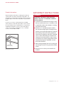
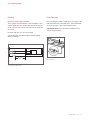
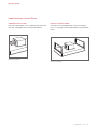
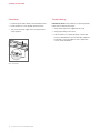
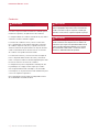
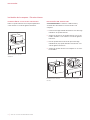
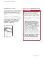
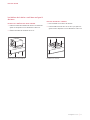
Product Information
Important product information, including the model and
serial number, are listed on the product rating plate. The
rating plate is located under the left side of the hood, above
the lters (lters must be removed). Refer to the illustration
below.
If service is necessary, contact Wolf Factory Certied
Service with the model and serial number. For the name of
the nearest Wolf Factory Certied Service or for questions
regarding the installation, visit the contact and support
section of our website, wolfappliance.com, or call Wolf
Customer Care at 800-222-7820.
CEILING-MOUNTED HOOD
IMPORTANT INSTRUCTIONS
WARNING
TO REDUCE THE RISK OF FIRE, ELECTRIC
SHOCK, OR INJURY TO PERSONS, OBSERVE
THE FOLLOWING:
a) Installation work and electrical wiring must be
done by qualied person(s) in accordance with
all applicable codes and standards, including
re-rated construction.
b) Sufcient air is needed for proper combus-
tion and exhausting of gases through the ue
(chimney) of fuel burning equipment to prevent
back drafting. Follow the heating equipment
manufacturer’s guideline and safety standards
such as those published by the National Fire
Protection Association (NFPA), and the Amer-
ican Society for Heating, Refrigeration and Air
Conditioning Engineers (ASHRAE), and the
local code authorities.
c) When cutting or drilling into wall or ceiling, do
not damage electrical wiring and other hidden
utilities.
d) Ducted fans must always be vented to the
outdoors.
Rating plate location
RATING PLATE
(ABOVE FILTERS)

4
|
Wolf Customer Care 800.222.7820
SITE PREPARATION
Ducting
WARNING
Use only metal ducting.
Consult a qualied HVAC professional for specic installa-
tion and ducting applications.
The hood accommodates a 6"
(152) round duct. Use only
rigid metal ducting.
A straight, short duct run is most effective and will ensure
proper performance. If the duct run exceeds 50'
(15 m), a
higher CFM blower may be required to maintain proper
airow. A remote blower installed on a short duct run may
increase the potential for noise.
Internal and in-line blowers require a roof or wall cap. Use
sheet metal screws and aluminum tape or high temperature
duct tape to seal joints between ducting sections.
The hood includes a backdraft damper. Local codes may
require the use of an additional backdraft and/or make-up
air damper. Contact your local HVAC professional for
specic requirements.
A make-up air damper is available through an authorized
Wolf dealer.
CAUTION
To reduce the risk of re and to properly exhaust air,
duct air outside. Do not vent exhaust air into spaces
within walls, ceilings, attics, crawl spaces, or garages.
CAUTION
To reduce the risk of re and electrical shock, only
install this range hood with remote blower models
rated a maximum of 3A suitable for use with solid state
speed control or internal blowers manufactured by
Wolf, “Blower—600 CFM”.

wolfappliance.com
|
5
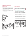
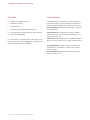
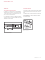
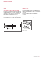
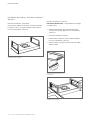
Ducting
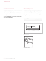
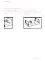
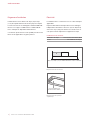
RECIRCULATION APPLICATION
The hood with an internal blower, can be installed in a recir-
culation application. The air discharge must be a minimum
of 40"
(102) from every side of the hood. Refer to the illustra-
tion below.
Ductwork and vent cover are not provided.
A recirculation kit, available through an authorized Wolf
dealer, is required.
40"
(
1016
)
MIN
Recirculation application
SITE PREPARATION
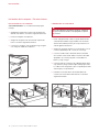
Filter Removal
To access the grease lters, pull down the front edge of the
bottom panel of the hood and allow it to rotate downward.
To remove the lters, refer to the illustration below.
IMPORTANT NOTE: Do not operate the ventilation hood
without the grease lters.
FILTER
Filter removal

6
|
Wolf Customer Care 800.222.7820
Installation Requirements
Install the hood 36" (914) to 84" (2134) from the bottom of the
hood to the countertop.
The hood requires a 600 CFM internal or in-line blower
assembly, or a 600 CFM or 1200 CFM remote blower
assembly, available through an authorized Wolf dealer.
Consult a qualied HVAC professional for specic installa-
tion and ducting applications.
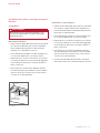
SPECIFICATIONS
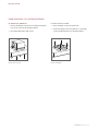
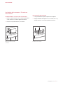
Electrical Requirements
Installation must comply with all applicable electrical codes.
Locate the electrical supply within the shaded area shown
in the illustration below. Allow a minimum 12"
(305) wire
(Romex) for connection. A separate circuit servicing only
this appliance is required.
ELECTRICAL REQUIREMENTS
Electrical Supply grounded, 120 VAC, 60 Hz
Service 15 amp dedicated circuit
Rating plate location
RATING PLATE
(ABOVE FILTERS)
E
36"
(914) TO 84" (2134) BOTTOM EDGE TO COUNTERTOP
Electrical location

wolfappliance.com
|
7
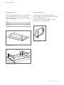
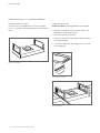
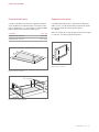
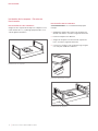
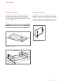
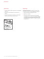
Mounting Brackets
To determine the height of the adjustable mounting
brackets, subtract 5"
(127) from the support framing height
(e.g. support framing height – 5" = H).
Use the
3
/8" (10) length screws provided to secure the
brackets. Refer to the illustration below.
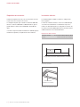
Ceiling Preparation
Refer to the chart and illustrations below for opening dimen-
sions and typical framing. Construct the framing using
minimum 2" x 4" lumber. Framing must be able to support a
minimum of 100 lb
(45 kg).
HOOD
W
36" Hood 34
1
/2" (873)
48" Hood 46
1
/4" (1175)
H
Bracket adjustment
12
3
/8
" (314) MIN TO
17
3
/4
" (451) MAX
Support framing (typical)
W
20"
(
508
)
Opening dimensions
SPECIFICATIONS

8
|
Wolf Customer Care 800.222.7820
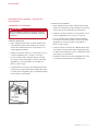
INSTALLATION
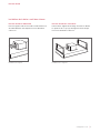
BLOWER INSTALLATION
IMPORTANT NOTE: The blower must be installed and
plugged in prior to making the electrical connection to the
hood.
1 Insert the round discharge on the blower into the round
discharge on the blower box.
2 Secure the blower to the blower box with the two screws
provided with the blower. Refer to the illustration below.
3 Rotate the blower box so the 6" (152) round discharge is
properly located. Refer to the illustration below.
4 Secure the blower box to the hood with the existing
screws.
Internal blower installation
Discharge direction
Hood Installation—Internal Blower
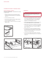
BLOWER BOX REMOVAL
Remove the blower box from the hood by removing the four
screws. Refer to the illustration below.
Blower box removal

wolfappliance.com
|
9
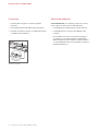
Hood Installation—Internal Blower
DAMPER INSTALLATION
Place the round damper on the round discharge and secure
with duct sealing tape. Refer to the illustration below.
Damper installation
INSTALLATION
BRACKET INSTALLATION
Secure the two mounting brackets to the hood using the
four
9
/16" (14) length screws provided. Refer to the illustration
below.
Bracket installation

10
|
Wolf Customer Care 800.222.7820
Hood Installation—Internal Blower
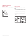
HOOD INSTALLATION
IMPORTANT NOTE: Mounting hardware is not provided.
1 Verify the control panel on the hood is located on the
right. Refer to the illustration below.
2 Insert the hood into the opening.
3 Secure the hood to the ceiling support framing. Refer to
the illustration below.
4 Connect the ductwork to the damper, then secure with
duct sealing tape.
Hood installation
INSTALLATION
WIRING CONNECTIONS
WARNING
Before making electrical connections, make sure the
electrical power is turned off at the service panel.
1 Remove the knockout above the home supply junction
box, then insert the home electrical supply (Romex) into
the electrical box. Refer to the illustration below.
2 Secure the electrical supply to the electrical box with a
UL or C/UL approved connector (not provided).
3 Connect the green or bare ground wire to the green
grounding screw. Use appropriate wire connectors (not
provided) to connect white to white and black to black.
4 Place all wiring connections inside the electrical box and
then install the cover. Verify all wires are secure and not
pinched between the cover and electrical box.
5 Insert the plug from the control board housing into the
receptacle on the blower. Refer to the illustration below.
HOME
SUPPLY
BLOWER
RECEPTACLE
Wiring connections
Blower connection
Control panel location

wolfappliance.com
|
11
FLANGE INSTALLATION
1 Place the ange on the top of the hood.
2 Secure the ange to the hood with the
1
/4" (6) length
screws provided. Refer to the illustration below.
INSTALLATION
Hood Installation—In-Line/Remote Blower
BLOWER BOX REMOVAL
1 Remove the blower box from the hood by removing the
four screws. Refer to the illustration below.
2 Discard the blower box and screws.
Blower box removal
Flange installation

12
|
Wolf Customer Care 800.222.7820
INSTALLATION
Hood Installation—In-Line/Remote Blower
BRACKET INSTALLATION
Secure the two mounting brackets to the hood using the
four
9
/16" (14) length screws provided. Refer to the illustration
below.
HOOD INSTALLATION
IMPORTANT NOTE: Mounting hardware is not provided.
1 Verify the control panel on the hood is located on the
right. Refer to the illustration below.
2 Insert the hood into the opening.
3 Secure the hood to the ceiling support framing. Refer to
the illustration below.
4 Connect the ductwork to the damper, then secure with
duct sealing tape.
Hood installation
Bracket installation
Control panel location

wolfappliance.com
|
13
Hood Installation—In-Line/Remote Blower
WIRING CONNECTIONS
WARNING
Before making electrical connections, make sure the
electrical power is turned off at the service panel.
Home Supply:
1 Remove the knockout above the home supply junction
box, then insert the home electrical supply (Romex) into
the electrical box. Refer to the illustration below.
2 Secure the electrical supply to the electrical box with a
UL or C/UL approved connector (not provided).
3 Connect the green or bare ground wire to the green
grounding screw. Use appropriate wire connectors (not
provided) to connect white to white and black to black.
4 Place all wiring connections inside the electrical box and
then install the cover. Verify all wires are secure and not
pinched between the cover and electrical box.
In-Line/Remote Supply:
1 Remove the knockout above the in-line/remote blower
junction box, then insert the blower electrical supply
(Romex) into the electrical box.
2 Secure the electrical supply to the electrical box with a
UL or C/UL approved connector (not provided).
3 Connect the green or bare ground wire to the green
grounding screw. Use appropriate wire connectors (not
provided) to connect white to white and black to black.
4 Place all wiring connections inside the electrical box and
then install the cover. Verify all wires are secure and not
pinched between the cover and electrical box.
5 Insert the plug from the control board housing into the
receptacle on the side of the junction box.
wolfappliance.com
|
13
INSTALLATION
IN-LINE/REMOTE
BLOWER
HOME
SUPPLY
Wiring connections

14
|
Wolf Customer Care 800.222.7820
Completion
1 Install the grease lters. Refer to the illustration below.
2 Rotate the bottom cover upward and into position.
3 Turn on the electrical supply at the circuit panel and
verify operation.
Troubleshooting
IMPORTANT NOTE: If the hood does not operate properly,
follow these troubleshooting steps:
1 Verify electrical power is supplied to the hood.
2 Verify proper wiring connections.
3 If the hood does not operate properly, contact Wolf
Factory Certied Service. Do not attempt to repair the
hood. Wolf is not responsible for service required to
correct a faulty installation.
TROUBLESHOOTING
FILTER
Filter installation

Sub-Zero, Sub-Zero & Design, Sub-Zero & Snowake Design, Dual Refrigeration, The Living Kitchen, Great American Kitchens The Fine Art of Kitchen Design, Wolf, Wolf &
Design, Wolf Gourmet, W & Design, red colored knobs, Cove, and Cove & Design are registered trademarks and service marks of Sub-Zero Group, Inc. and its subsidiaries.
All other trademarks are property of their respective owners in the United States and other countries.
wolfappliance.com
|
15

2
|
Atención al cliente de Wolf 800.222.7820
CAMPANA INSTALADA EN EL TECHO
Aviso importante
Para garantizar que este producto se instale y opere de
la forma más segura y eciente posible, tome nota de los
siguientes tipos de información resaltada en este manual:
AVISO IMPORTANTE señala la información que es especial-
mente importante.
PRECAUCIÓN indica una situación en la que se pueden
sufrir heridas leves o provocar daños al producto si no se
siguen las instrucciones.
ADVERTENCIA indica peligro de que se produzcan heridas
graves o incluso la muerte si no se siguen las precauciones.
AVISO IMPORTANTE: en toda esta guía, las dimensiones
entre paréntesis son milímetros, a menos que se especi-
que lo contrario.
AVISO IMPORTANTE: guarde estas instrucciones para el
inspector eléctrico local.
Contenido
3 Campana instalada en el techo
4 Preparación del sitio
6 Especicaciones
8 Instalación de la campana: Extractor interno
11 Instalación de la campana: Extractor en línea/remoto
14 Resolución de problemas
Las características y especicaciones están sujetas a cam-
bios sin previo aviso. Visite wolfappliance.com/specs para
obtener la información más actualizada.

wolfappliance.com
|
3
Información del producto
La información importante del producto, incluido el modelo
y número de serie de la unidad, se encuentra en la placa de
datos del producto, que está debajo del costado izquierdo
de la campana, encima de los ltros (se deben retirar los
ltros). Consulte la siguiente ilustración.
Si es necesario realizar algún servicio, póngase en con-
tacto con el Servicio certicado de fábrica de Wolf y tenga
a mano el modelo y el número de serie. Para obtener los
datos del centro de Servicio certicado de fábrica de Wolf
más cercano o si tiene preguntas acerca de la instalación,
visite la sección de contacto y soporte técnico en nuestra
página de Internet wolfappliance.com; o bien, llame a la
línea de atención al cliente de Wolf al 800-222-7820.
CAMPANA INSTALADA EN EL TECHO
INSTRUCCIONES
IMPORTANTES
ADVERTENCIA
PARA REDUCIR EL RIESGO DE INCENDIO,
DESCARGA ELÉCTRICA O LESIONES A
LAS PERSONAS, TOME LAS SIGUIENTES
PRECAUCIONES:
a) Una persona calicada debe realizar el trabajo
de instalación y cableado eléctrico de confor-
midad con todos los códigos y normas aplica-
bles, incluyendo la de construcción a prueba
de fuego.
b) Se necesita suciente aire para permitir una
combustión y escape de gases adecuados
por el tubo de chimenea del equipo quemador
de combustible para evitar que se produzcan
llamaradas. Siga las directrices del fabricante
del equipo de calefacción y las normas de
seguridad como las publicadas por la Asocia-
ción Nacional de Protección contra Incendios
(NFPA, por sus siglas en inglés) y la Sociedad
Estadounidense de Ingenieros en Calefacción,
Refrigeración y Aire Acondicionado (ASHRAE,
por sus siglas en inglés) y los códigos de las
autoridades locales.
c) Al cortar o perforar la pared o el techo, no
dañe el cableado eléctrico ni otros servicios
ocultos.
d) Los ventiladores con conductos siempre
deben descargarse hacia el exterior.
Ubicación de la placa de datos
PLACA DE DATOS
(ENCIMA DE LOS FILTROS)

4
|
Atención al cliente de Wolf 800.222.7820
PREPARACIÓN DEL SITIO
Conductos
ADVERTENCIA
Utilice solamente conductos metálicos.
Consulte a un profesional de climatización calicado para la
instalación especíca y las aplicaciones de conductos.
La campana admite un conducto redondo de 6"
(152). Utilice
solamente conductos metálicos rígidos.
Los tramos de conductos cortos y rectos son más efec-
tivos y garantizarán un desempeño adecuado. Si el tramo
de conducto supera los 50'
(15 m), se puede necesitar un
extractor CFM más alto para mantener un ujo de aire ade-
cuado. La instalación de un extractor remoto en un tramo
de conducto corto puede aumentar el ruido.
Los extractores internos y en línea necesitan una rejilla de
techo o de pared. Utilice tornillos de metal y cinta de alu-
minio o cinta para conductos de alta temperatura para sellar
las uniones entre las secciones de conductos.
La campana incluye una compuerta de contraujo de aire.
Es posible que los códigos locales exijan que se utilice
una compuerta adicional de contraujo o aire renovable.
Comuníquese con un profesional local de climatización para
conocer los requisitos especícos.
Una compuerta de aire renovable está disponible a través
de un distribuidor autorizado de Wolf.
PRECAUCIÓN
Para reducir el riesgo de incendio y extraer el aire de
manera apropiada, dirija el aire hacia el exterior. No
ventile el aire del escape en espacios cerrados por
paredes, techos, áticos, espacios angostos o garajes.
PRECAUCIÓN
Para reducir el riesgo de incendio y descargas eléctricas,
instale solamente esta campana con los modelos de
extractores que tengan una capacidad máxima de 3A
y que sean adecuados para utilizarlos con el control
de velocidad de estado sólido o el extractor interno
“Extractor—600 CFM” fabricado por Wolf.

wolfappliance.com
|
5
Conductos
APLICACIÓN DE RECIRCULACIÓN
La campana con un extractor interno se puede instalar en
una aplicación de recirculación. La descarga de aire debe
ser de un mínimo de 40"
(102) desde cada lado de la cam-
pana. Consulte la siguiente ilustración.
No se suministran los conductos y la tapa de la ventilación.
Se requiere un kit de recirculación, disponible a través de un
distribuidor autorizado de Wolf.
40"
(
1016
)
MÍNIMO
Aplicación de recirculación
PREPARACIÓN DEL SITIO
Extracción del ltro
Para acceder a los ltros de grasa, hale hacia abajo el borde
frontal del panel inferior de la campana y déjelo rotar hacia
abajo.
Para retirar los ltros, consulte la ilustración a continuación.
AVISO IMPORTANTE: no opere la campana de ventilación
sin los ltros de grasa.
FILTRO
Extracción del ltro

6
|
Atención al cliente de Wolf 800.222.7820
Requisitos de instalación
Instale la campana a 36" (914) y 84" (2134) de distancia desde
la parte inferior de la campana a la encimera
.
La campana requiere que se instale un extractor 600 CFM
interno o en línea o 600 CFM o 1200 CFM remoto, que se
puede obtener a través de un distribuidor autorizado de
Wolf.
Consulte a un profesional de climatización calicado para la
instalación especíca y las aplicaciones de conductos.
ESPECIFICACIONES
Instalación eléctrica
La instalación debe cumplir con todos los códigos eléc-
tricos vigentes.
Localice el suministro eléctrico en la zona sombreada que
se muestra en la ilustración a continuación. Deje como
mínimo un cable (Romex) de 12"
(305) para la conexión. Se
necesita un circuito independiente que le suministre electri-
cidad únicamente a este electrodoméstico.
REQUISITOS ELÉCTRICOS
Suministro eléctrico Con conexión a tierra, 120 V CA, 60 Hz
Servicio Circuito exclusivo de 15 amperes
Ubicación de la placa de datos
PLACA DE DATOS
(ENCIMA DE LOS FILTROS)
E
36"
(914) A 84" (2134) DESDE EL BORDE INFERIOR A LA ENCIMERA
Ubicación eléctrica
A página está carregando...
A página está carregando...
A página está carregando...
A página está carregando...
A página está carregando...
A página está carregando...
A página está carregando...
A página está carregando...
A página está carregando...
A página está carregando...
A página está carregando...
A página está carregando...
A página está carregando...
A página está carregando...
A página está carregando...
A página está carregando...
A página está carregando...
A página está carregando...
A página está carregando...
A página está carregando...
A página está carregando...
A página está carregando...
A página está carregando...
A página está carregando...
-
 1
1
-
 2
2
-
 3
3
-
 4
4
-
 5
5
-
 6
6
-
 7
7
-
 8
8
-
 9
9
-
 10
10
-
 11
11
-
 12
12
-
 13
13
-
 14
14
-
 15
15
-
 16
16
-
 17
17
-
 18
18
-
 19
19
-
 20
20
-
 21
21
-
 22
22
-
 23
23
-
 24
24
-
 25
25
-
 26
26
-
 27
27
-
 28
28
-
 29
29
-
 30
30
-
 31
31
-
 32
32
-
 33
33
-
 34
34
-
 35
35
-
 36
36
-
 37
37
-
 38
38
-
 39
39
-
 40
40
-
 41
41
-
 42
42
-
 43
43
-
 44
44


Wolf 5610506 Guia de instalação
- Categoria
- Exaustores
- Tipo
- Guia de instalação
em outras línguas
- español: Wolf 5610506 Guía de instalación
- français: Wolf 5610506 Guide d'installation
- English: Wolf 5610506 Installation guide
Artigos relacionados
Outros documentos
-
Sub-Zero VC36S Guia de instalação
-
-
Sub-Zero DO30PM/S/PH Guia de instalação
-
Thermador VCIN54GWS Guia de instalação
-
-
Broan B5936SS Guia de instalação
-
 Kenmore Elite 23355802110 Manual do proprietário
-
Sub-Zero CG365C/S Guia de instalação
-
-
Thermador HMWN48FS Guia de instalação
