
24" E SERIES OVEN
INSTALLATION GUIDE
SPECIFICATIONS, INSTALLATION, AND MORE

24" E SERIES OVEN
2
|
Wolf Customer Care 800.222.7820
Contents
3 24" E Series Oven
4 Specications
8 Installation
10 Troubleshooting
Features and specications are subject to change at any
time without notice. Visit wolfappliance.com/specs for the
most up-to-date information.
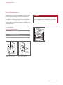
Important Note
To ensure this product is installed and operated as safely
and efciently as possible, take note of the following types
of highlighted information throughout this guide:
IMPORTANT NOTE highlights information that is especially
important.
CAUTION indicates a situation where minor injury or product
damage may occur if instructions are not followed.
WARNING states a hazard that may cause serious injury or
death if precautions are not followed.
IMPORTANT NOTE: Throughout this guide, dimensions in
parentheses are millimeters unless otherwise specied.
IMPORTANT NOTE: Save these instructions for the local
electrical inspector.

wolfappliance.com
|
3
24" E SERIES OVEN
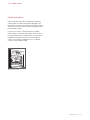
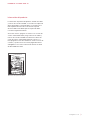
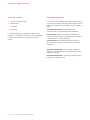
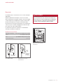
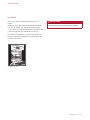
Product Information
Important product information, including the model and
serial number, are listed on the product rating plate. The
rating plate is located on the left side of the front face frame.
The oven door must be open to view the rating plate. Refer
to the illustration below.
If service is necessary, contact Wolf Factory Certied
Service with the model and serial number. For the name of
the nearest Wolf Factory Certied Service or for questions
regarding the installation, visit the contact and support
section of our website, wolfappliance.com, or call Wolf
Customer Care at 800-222-7820.
Rating plate location
RATING PLATE

4
|
Wolf Customer Care 800.222.7820
SPECIFICATIONS
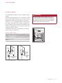
Installation Requirements
The oven can be installed in a standard or ush inset appli-
cation. If a cooktop is installed above the oven, a minimum
of
1
/4" (6) is required between the units.
Finish the edges of the opening. They may be visible when
the door is open.
For standard installations, the face trim overlaps stiles and
rails. Refer to the chart.
For ush inset installations, a minimum
1
/8" (3) reveal is
required on all sides. To ensure consistent reveals, each
corner of the opening must be exactly 90°.
INSTALLATION REQUIREMENTS
BASE SUPPORT MIN
24" E Series Oven 150 lb (68 kg)
TRIM OVERLAP
Top
1
/4" (6)
Bottom 0" (0)
Sides
11
/16" (17)

wolfappliance.com
|
5
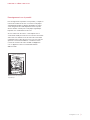
Electrical Requirements
Installation must comply with all applicable electrical codes.
Locate the electrical supply as shown in the illustrations
on the following pages. A separate circuit servicing only
this appliance is required. A ground fault circuit interrupter
(GFCI) is not recommended and may cause interruption of
operation. Refer to the illustration below for minimum power
cord plug clearance.
Performance may be compromised if the electrical supply is
less than 240 volts.
ELECTRICAL REQUIREMENTS
Electrical Supply grounded, 240/208 VAC, 60 Hz
Service 20 amp dedicated circuit
Receptacle NEMA 6-20R grounding-type
Power Cord 6'
(1.8 m)
WARNING
ELECTRICAL SHOCK HAZARD: Plug into a grounded
3-prong outlet. Do not remove the ground prong. Do
not use an adapter. Failure to follow these instructions
can result in electric shock, re, or death.
SPECIFICATIONS
Rating plate location
RATING PLATE
NEMA
PLUG
GROUNDED
NEMA RECEPTACLE
1" (25)
MINIMUM
CORD
CLEARANCE
NEMA 6-20R receptacle
Power cord clearance

6
|
Wolf Customer Care 800.222.7820
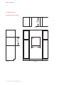
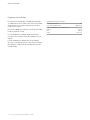
SPECIFICATIONS
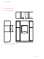
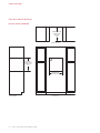
24" E Series Oven
STANDARD INSTALLATION
E
FRONT VIEW
SIDE
VIEW
23
1
/
4
"
(591)
OPENING
HEIGHT
23" (584)
OPENING
DEPTH
TOP VIEW
22
1
/8" (562)
OPENING WIDTH

wolfappliance.com
|
7
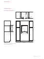
SPECIFICATIONS
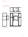
E
23
3
/4" (603)
FLUSH INSET WIDTH**
FRONT VIEW
SIDE
VIEW
24" (610)
FLUSH
INSET
DEPTH
7
/8" (22)
*W
ill be visible and should be finished to match cabinetry.
**
Dimension provides minimum reveals.
23
3
/4" (603)
FLUSH INSET
HEIGHT**
3
/8" (10)
1
/8" (3)
TOP VIEW
13
/16" (21)
FINISHED
CLEATS*
24" E Series Oven
FLUSH INSET INSTALLATION

8
|
Wolf Customer Care 800.222.7820
INSTALLATION
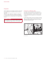
Preparation
Before moving the oven, protect any nished ooring and
secure the oven door(s) closed to prevent damage.
Use an appliance dolly to move the unit near the opening.
Remove and recycle packing materials. Do not lift or carry
the oven by the door handle.
CAUTION
Do not lift the oven by the door handle. This will
damage the oven door and hinges.
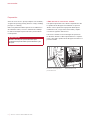
OVEN DOOR REMOVAL
To remove, open the oven door completely. Rotate both
hinge latches forward to the open position. Close the door
to approximately 30° open, then lift up and out. Refer to the
illustrations below.
To reinstall, insert the door hinges into the frame open-
ings. Open the oven door completely and rotate both hinge
latches back to the closed position.
OPEN
POSITION
CLOSED
POSITION
Oven door hinge latch
Door open 30°

wolfappliance.com
|
9
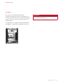
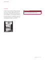
Installation
Place the oven in the opening and slide back.
Locate the mounting holes on the oven side trim, two on
each side. Drill
1
/16" pilot holes. Use the provided mounting
screws to secure the oven to the cabinetry. Refer to the
illustration below.
To avoid interference, a 90° door stop may be required for
any appliance or cabinet door installed next to the oven.
MOUNTING
HOLES
Oven installation
INSTALLATION
CAUTION
Failure to install the mounting screws may cause the
oven to tip forward during use.

10
|
Wolf Customer Care 800.222.7820
TROUBLESHOOTING
Troubleshooting
IMPORTANT NOTE: If the oven does not operate properly,
follow these troubleshooting steps:
• Verify electrical power is supplied to the oven.
• Verify proper electrical connections.
• If the oven does not operate properly, contact Wolf
Factory Certied Service. Do not attempt to repair the
oven. Wolf is not responsible for service required to
correct a faulty installation.

Sub-Zero, Sub-Zero & Design, Sub-Zero & Snowake Design, Dual Refrigeration, The Living Kitchen, Great American Kitchens The Fine Art of Kitchen Design, Wolf, Wolf &
Design, Wolf Gourmet, W & Design, red colored knobs, Cove, and Cove & Design are registered trademarks and service marks of Sub-Zero Group, Inc. and its subsidiaries.
All other trademarks are property of their respective owners in the United States and other countries.

2
|
Atención al cliente de Wolf 800.222.7820
HORNO DE LA SERIE E DE 24"
Contenido
3 Horno de la serie E de 24"
4 Especicaciones
8 Instalación
10 Resolución de problemas
Las características y especicaciones están sujetas a
cambios sin previo aviso. Visite wolfappliance.com/specs
para obtener la información más actualizada.
Aviso importante
Para garantizar que este producto se instale y opere de
la forma más segura y eciente posible, tome nota de los
siguientes tipos de información resaltada en esta guía:
AVISO IMPORTANTE señala la información que es
especialmente importante.
PRECAUCIÓN
indica una situación en la que se pueden
sufrir heridas leves o provocar daños al producto si no se
siguen las instrucciones.
ADVERTENCIA indica peligro de que se produzcan heridas
graves o incluso la muerte si no se siguen las precauciones.
AVISO IMPORTANTE: En toda esta guía, las dimensiones
entre paréntesis son milímetros, a menos que se especique
lo contrario.
AVISO IMPORTANTE: Guarde estas instrucciones para el
inspector eléctrico local.

wolfappliance.com
|
3
HORNO DE LA SERIE E DE 24"
Información del producto
La información importante del producto, incluido el modelo
y número de serie de la unidad, se encuentra en la placa de
datos del producto. La placa de datos se encuentra en el
lado izquierdo del marco de la cara frontal. La puerta
del horno debe estar abierta para ver la placa de datos.
Consulte la siguiente ilustración.
Si necesita servicio, póngase en contacto con el centro de
servicio autorizado de Wolf y tenga a la mano el modelo y
número de serie de la unidad. Para obtener los datos del
centro de servicio autorizado de Wolf más cercano o si
tiene preguntas acerca de la instalación, visite la sección de
contacto y soporte técnico en nuestra página de Internet
wolfappliance.com o llame a la línea de atención al cliente
de Wolf al 800-222-7820.
Ubicación de la placa de datos
PLACA DE DATOS

4
|
Atención al cliente de Wolf 800.222.7820
ESPECIFICACIONES
Requisitos de instalación
El horno se puede instalar en una aplicación estándar o
empotrable. Si se instala una estufa sobre el horno, se
requiere un espacio mínimo de
1
/4" (6) entre las unidades.
Dé el acabado a los bordes de la abertura. Pueden ser
visibles cuando la puerta está abierta.
Para instalaciones estándares, el ribete frontal se super-
pondrá a los largueros y las guías. Consulte la tabla.
Para las instalaciones empotrables se requiere un margen
mínimo de
1
/8" (3) en todos los lados. Para asegurar
márgenes consistentes, cada esquina de la abertura
debe tener exactamente 90º.
REQUISITOS DE INSTALACIÓN
SOPORTE DE LA BASE MIN
Hornos de la serie E de 24" 150 lb (68 kg)
SUPERPOSICIÓN DEL RIBETE
Parte superior
1
/4" (6)
Parte inferior 0" (0)
Laterales
11
/16" (17)

wolfappliance.com
|
5
Instalación eléctrica
La instalación debe cumplir con todos los códigos eléctricos
vigentes.
Coloque el suministro eléctrico como se muestra en las ilus-
traciones de las páginas siguientes. Es necesario un circuito
independiente que dé servicio únicamente a este electro-
doméstico. No es recomendable utilizar un circuito de fallos
de conexión a tierra (GFCI, por sus siglas en inglés) ya que
puede interrumpir el funcionamiento de la unidad. Consulte
la ilustración siguiente para conocer el espacio mínimo del
enchufe del cable de corriente.
El rendimiento puede verse comprometido si el suministro
eléctrico es menor a 240 voltios.
REQUISITOS ELÉCTRICOS
Suministro eléctrico Con conexión a tierra, 240/208 V CA, 60 Hz
Servicio Circuito dedicado de 20 amperes
Receptáculo Tipo de conexión a tierra NEMA 6-20R
Cable de alimentación
eléctrica
6'
(1.8 m)
ADVERTENCIA
PELIGRO DE DESCARGA ELÉCTRICA Enchufe en
enchufe de 3 patas con conexión a tierra. No retire
la clavija de conexión a tierra. No use un adaptador.
No cumplir con estas instrucciones puede producir
una descarga eléctrica, fuego o muerte.
ESPECIFICACIONES
Ubicación de la placa de datos
PLACA DE DATOS
NEMA
PLUG
GROUNDED
NEMA RECEPTACLE
1" (25)
MINIMUM
CORD
CLEARANCE
Receptáculo NEMA 6-20R
Espacio libre para el cable
ESPACIO
LIBRE MÍNIMO
PARA EL
CABLE
RECEPTÁCULO NEMA
CON CONEXIÓN A
TIERRA
ENCHUFE
NEMA

6
|
Atención al cliente de Wolf 800.222.7820
ESPECIFICACIONES
Horno de la serie E de 24"
INSTALACIÓN ESTÁNDAR
E
VISTA FRONTAL
VIST
A LATERAL
23
1
/
4
"
(591)
ALTURA DE
LA ABERTURA
23"
(584)
PROFUNDIDAD DE
LA ABERTURA
VISTA SUPERIOR
22
1
/8" (562)
ANCHO DE
LA ABERTURA

wolfappliance.com
|
7
ESPECIFICACIONES
E
23
3
/4" (603)
ANCHO DE LA
INSTALACIÓN
EMPOTRABLE**
VISTA FRONTAL
VIST
A LATERAL
24" (610)
PROFUNDIDAD DE
LA INSTALACIÓN
EMPOTRABLE
7
/8" (22)
*
Será visible y debe tener un acabado que haga juego con los gabinetes.
**
La dimensión especifica los márgenes mínimos.
23
3
/4" (603)
ALTURA DE
LA INSTALACIÓN
EMPOTRABLE
**
3
/8" (10)
1
/8" (3)
VISTA SUPERIOR
13
/16" (21)
CORNAMUSAS
TERMINADAS*
Horno de la serie E de 24"
INSTALACIÓN EMPOTRABLE

8
|
Atención al cliente de Wolf 800.222.7820
INSTALACIÓN
Preparación
Antes de mover el horno, proteja cualquier suelo acabado y
asegúrese de que la(s) puerta(s) del horno esté(n) cerrada(s)
para que no se dañe(n).
Utilice una plataforma rodante para mover la unidad cerca
de la abertura. Retire y recicle los materiales de embalaje.
No utilice la manija de la puerta del horno para levantarlo
ni transportarlo.
PRECAUCIÓN
No utilice la manija de la puerta del horno para
levantarlo. Esto puede dañar la puerta del horno y las
bisagras.
CÓMO QUITAR LA PUERTA DEL HORNO
Para quitar la puerta del horno, ábrala completamente. Gire
los pestillos de las bisagras hacia adelante a la posición
abierta. Cierre la puerta hasta que quede abierta aproxi-
madamente a 30º y luego levante hacia arriba y sáquela.
Consulte las siguientes ilustraciones.
Para volver a instalar, inserte las bisagras de la puerta en
las aberturas del marco. Abra la puerta del horno completa-
mente y gire ambos pestillos de las bisagras hacia atrás a la
posición cerrada.
EN POSICIÓN
ABIERTA
POSICIÓN
CERRADA
Pestillo de la bisagra de la
puerta del horno
Puerta abierta a 30°

wolfappliance.com
|
9
Instalación
Coloque el horno en la abertura y deslícelo hacia atrás.
Localice los oricios de montaje en el ribete lateral del
horno, dos de cada lado. Taladre oricios guía de
1
/16".
Use los tornillos de montaje provistos para asegurar el
horno a los gabinetes. Consulte la siguiente ilustración.
Para evitar interferencias, es posible que se requiera un
tope para puerta a 90º para un electrodoméstico o una
puerta de gabinete instalado cerca del horno.
INSTALACIÓN
PRECAUCIÓN
Si no se instalan los tornillos de montaje, el horno se
puede volcar hacia adelante durante su uso.
MOUNTING
HOLES
Instalación del horno
ORIFICIOS
DE MONTAJE

10
|
Atención al cliente de Wolf 800.222.7820
RESOLUCIÓN DE PROBLEMAS
Resolución de problemas
AVISO IMPORTANTE: si el horno no funciona correctamente,
siga estos pasos para resolver los problemas:
• Compruebe que el horno tiene corriente eléctrica.
• Compruebe que las conexiones eléctricas estén
correctas.
• Si el horno no funciona correctamente, póngase en
contacto con el centro de servicio autorizado de Wolf.
No intente reparar el horno. Wolf no es responsable
del servicio necesario para corregir una instalación
defectuosa.
A página está carregando...
A página está carregando...
A página está carregando...
A página está carregando...
A página está carregando...
A página está carregando...
A página está carregando...
A página está carregando...
A página está carregando...
A página está carregando...
A página está carregando...
A página está carregando...
-
 1
1
-
 2
2
-
 3
3
-
 4
4
-
 5
5
-
 6
6
-
 7
7
-
 8
8
-
 9
9
-
 10
10
-
 11
11
-
 12
12
-
 13
13
-
 14
14
-
 15
15
-
 16
16
-
 17
17
-
 18
18
-
 19
19
-
 20
20
-
 21
21
-
 22
22
-
 23
23
-
 24
24
-
 25
25
-
 26
26
-
 27
27
-
 28
28
-
 29
29
-
 30
30
-
 31
31
-
 32
32


