Sub-Zero DW2450WS Guia de instalação
- Categoria
- Máquinas de lavar louça
- Tipo
- Guia de instalação
Este manual também é adequado para

DISHWASHER
INSTALLATION GUIDE
SPECIFICATIONS, INSTALLATION, AND MORE

2 | Cove Customer Care 800.222.7820
COVE DISHWASHER
Contents
3 Cove Dishwasher
4 Specications
7 Door Panel
9 Installation
15 Troubleshooting
Features and specications are subject to change at any
time without notice. Visit coveappliance.com/specs for the
most up-to-date information.
Important Note
To ensure this product is installed and operated as safely
and efciently as possible, take note of the following types
of highlighted information throughout this guide:
IMPORTANT NOTE highlights information that is especially
important.
CAUTION indicates a situation where minor injury or product
damage may occur if instructions are not followed.
WARNING states a hazard that may cause serious injury or
death if precautions are not followed.
IMPORTANT NOTE: Throughout this guide, dimensions in
parentheses are millimeters unless otherwise specied.
IMPORTANT NOTE: Certied residential dishwashers are not
intended for licensed food establishments.
IMPORTANT NOTE: Exercise care when installing and
removing the unit to avoid damage to the power supply cord
(#827613).

coveappliance.com | 3
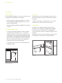
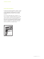
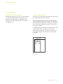
Product Information
Important product information, including the model and
serial number, are listed on the product rating plate. The
rating plate is located on the left side wall of the unit. Refer
to the illustration below.
If service is necessary, contact Cove Factory Certied
Service with the model and serial number. For the name
of the nearest Cove Factory Certied Service or for ques-
tions regarding the installation, visit the contact and support
section of our website, coveappliance.com, or call Cove
Customer Care at 800-222-7820.
RATING PLATE
Rating plate location
COVE DISHWASHER
4 | Cove Customer Care 800.222.7820
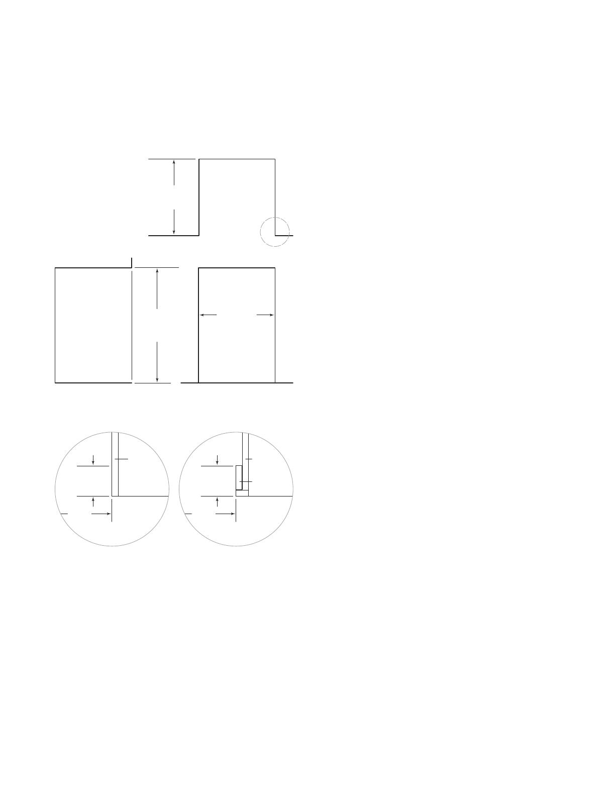
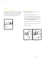
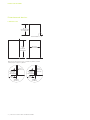
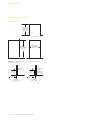
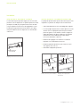
SPECIFICATIONS
23
5
/8" (600)
OPENING WIDTH
34
1
/
2
"
(876)
OPENING
HEIGHT
TOP VIEW
SIDE
VIEW FRONT VIEW
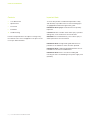
NOTE:
3
1
/2" (89) finished returns will be visible and should be finished to match cabinetry.
3
/4" (19)
TYPICAL
FRAMED
CABINETRY
23
5
/8"
(600)
FILLER
3
1
/2" (89)
FINISHED
RETURN
FRAMELESS
CABINETRY
23
5
/8"
(600)
3
/4" (19)
TYPICAL
3
1
/2" (89)
FINISHED
RETURN
24" (610)
MIN OPENING
DEPTH
Opening Dimensions
DISHWASHER

coveappliance.com | 5
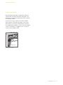
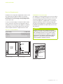
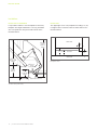
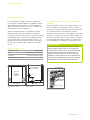
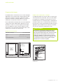
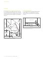
Electrical Requirements
Installation must comply with all applicable electrical codes.
Any opening into the adjacent cabinet must meet the
following: the longest dimension of the opening shall not
be more than 1
1
/2" (38). The edges of the opening must be
smooth and round.
Locate the electrical supply in an adjacent cabinet, within
reach of the power cord. Refer to the illustrations below.
A separate circuit servicing only this appliance is required.
A ground fault circuit interrupter (GFCI) outlet or breaker
may be required, whichever complies with local codes.
ELECTRICAL REQUIREMENTS
Electrical Supply 115 VAC, 60 Hz
Service 15 amp dedicated circuit
Receptacle 3-prong grounding-type
Power Cord
5
' (1.5 m)
E
E
ELECTRICAL
LOCATION
IN ADJACENT
CABINET
FRONT VIEW
5
1
/2" (140)
1
1
/2"
(
38
)
2" (51)
TOE KICK
SIDE VIEW
BACK OF
OPENING
Electrical location Electrical routing
GROUNDING INSTRUCTIONS
This appliance must be grounded. In the event of a malfunc-
tion or breakdown, grounding will reduce the risk of electric
shock by providing a path of least resistance for electric
current. This appliance is equipped with a cord having an
equipment-grounding conductor and a grounding plug.
The plug must be plugged into an appropriate outlet that is
installed and grounded in accordance with all local codes
and ordinances.
WARNING
Improper connection of the equipment-grounding
conductor can result in a risk of electric shock. Check
with a qualied electrician or service representative
if you are in doubt whether the appliance is properly
grounded. Do not modify the plug provided with the
appliance, if it will not t the outlet, have a proper
outlet installed by a qualied electrician.
RATING PLATE
Rating plate location
SPECIFICATIONS

6 | Cove Customer Care 800.222.7820
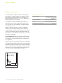
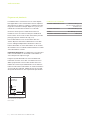
Plumbing Requirements
Installation must comply with all applicable plumbing codes.
Any opening into the adjacent cabinet must meet the
following: the longest dimension of the opening shall not
be more than 1
1
/2" (38). The edges of the opening must be
smooth and round.
A drain line high loop is factory installed on the unit. Do not
remove the high loop clamp. If necessary, the drain tubing
can be extended by a maximum of 5'
(1.5 m).
Locate the water supply and drain in an adjacent cabinet.
Route the water supply through the shaded area shown in
the illustration below. Connect the water supply to a hot
water house supply with an easily accessible shut-off valve
between the supply and the unit.
IMPORTANT NOTE: This appliance is intended for connec-
tion to a hot water supply. The water supply cannot be
exposed to freezing temperatures.
Purge the water supply prior to nal connection to the unit.
This will remove any debris that may be present in the
tubing from installing the new water supply. Connect the
braided tubing from the unit to the house water supply with
the tting provided. Check all water supply ttings for leaks.
5
1
/2" (140)
1
1
/2"
(
38
)
2" (51)
TOE KICK
SIDE VIEW
BACK OF
OPENING
Water supply routing
SPECIFICATIONS
PLUMBING REQUIREMENTS
Water Connection 5' (1.5 m) braided tubing with
3
/8" female compression tting
Drain Connection 5' (1.5 m) corrugated tubing
Pressure 30–140 psi
(2–9.7 bar)
Max Supply Temperature 140°F (60°C)

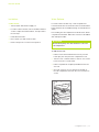
coveappliance.com | 7
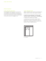
CUSTOM PANEL
Finish all sides of the custom panel. They may be visible
when the door is open.
The thickness of the custom panel can vary. A minimum
1
/2" (13) thick panel is required, but the thickness can be
increased provided the panel does not exceed 20 lb
(9 kg).
A panel less than 16 lb
(7 kg) is optimal.
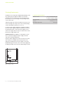
The custom door panel template provided accommodates
23
3
/8" (594) and 23
3
/4" (603) wide panels. Adjust the template
accordingly for all other panel widths. Refer to the illustra-
tion below.
Door Panel
STAINLESS STEEL PANEL
Stainless steel accessory door panels are available
through an authorized Cove dealer. For local dealer infor-
mation, visit the nd a showroom section of our website,
coveappliance.com.
DOOR PANEL
TOP OF PANEL
HOLES FOR
BOTTOM BRACKET
TOP OF DOOR PANEL
HOLES FOR
TOP BRACKET
24" [610 MM] OPENING (23 3/4" [603 MM] PANEL)
23 5/8" [600 MM] OPENING (23 3/8" [594 MM] PANEL)
LEFT EDGE OF DOOR
PANEL
RIGHT EDGE OF DOOR PANEL
Custom door panel template

8 | Cove Customer Care 800.222.7820
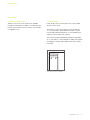
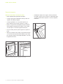
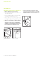
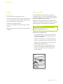
7 Verify the panel is secure against the dishwasher door,
then insert a screw into each hinge to secure the bottom
of the panel. Refer to the illustration below.
DOOR PANEL
Door Panel
CUSTOM PANEL MOUNTING
1 Remove the template from the dishwasher door.
2 Place the custom panel face down on a protected work
surface.
3 Position the template ush with the top and sides of the
panel, then mark and drill the holes.
4 Remove the custom panel mounting brackets from the
dishwasher by pushing in and up on each bracket. Refer
to the illustration below.
5 Use the screws provided to secure the brackets to the
panel.
6 Align the mounting pins on the door panel with the dish-
washer door slots, then push in and shift the panel down
to secure. Refer to the illustration below.
HINGE SCREW
Hinge screw
PANEL
MOUNTING
BRACKET
MOUNTING
PIN
Panel mounting brackets
Mounting pin

coveappliance.com | 9
INSTALLATION
Installation
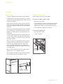
PREPARATION
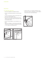
1 Place the unit in front of the opening.
2 For openings less than 24" (610) wide, remove the side
spacers by pushing upward. Refer to the illustration
below.
3 Measure the height of the opening, then adjust the
leveling legs until the unit height is slightly less than the
opening height. Refer to the illustration below.
To adjust the front, turn the leveling legs clockwise to
raise and counterclockwise to lower the unit.
To adjust the rear, turn the rear adjustment screw coun-
terclockwise to raise and clockwise to lower the unit.
NOTE: The unit is equipped to prevent the rear leveling
leg from stripping if turned the wrong way. If the rear
leveling leg does not raise or lower, tilt the dishwasher
forward slightly to remove pressure from the leg which
will engage the threads and allow for adjustment.
4 Route the power cord through an access hole in the
adjacent cabinet.
5 Route the water supply and drain tube through an
access hole in the adjacent cabinet.
SPACER
REAR
ADJUSTMENT
SCREW
FRONT
LEVELING
LEG
Side spacers
Leveling
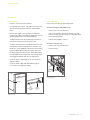
RACK REMOVAL
Remove the racks prior to anchoring the unit.
To remove the upper and middle racks:
1 Pull the rack out to full extension.
2 Pull out on the tab on the side of the rack clips and
remove the clips from the end of each rack glide. Refer
to the illustration below.
3 Pull the rack forward to remove.
To remove the lower rack:
1 Pull the rack out to full extension.
2 Lift up and out.
TAB
Rack removal

10 | Cove Customer Care 800.222.7820
INSTALLATION
LEVELING
To adjust the front, turn the leveling legs clockwise to raise
and counterclockwise to lower the unit. Refer to the illustra-
tion below.
To adjust the rear, turn the rear adjustment screw counter-
clockwise to raise and clockwise to lower the unit.
ANCHORING
Secure the unit to adjacent cabinetry using the screws
provided. Do not overtighten. Overtightening could distort
the unit causing issues with the door seal. If applicable,
secure the top of the unit to the countertop using the screws
provided.
Verify proper door closure, then install the hole plugs in each
mounting hole location. Refer to the illustration below.
Installation
INSTALLATION
For metal cabinet installations, contact Cove Customer Care
for edge protector material prior to installation.
1 Insert the unit into the opening and pull the excess elec-
trical and plumbing supplies through the access hole as
the unit is being installed.
2 Verify the plumbing and electrical supplies are not kinked
or coiled.
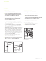
PLUMBING CONNECTIONS
1 Connect the drain tube following local code. The drain
connection will accommodate 1"
(25),
3
/4" (19), and
5
/8"
(16)
drain connections. The connection must be cut to t
3
/4" (19) and
5
/8" (16) connections. If connecting to a food
waste disposer, remove the knockout prior to making the
drain connection. The drain tube connection must be 20"
(508)
to 43" (1092) above the bottom of the dishwasher
leveling legs. Refer to the illustration below.
2 Connect the water connection to the water supply with
the tting provided.
REAR
ADJUSTMENT
SCREW
FRONT
LEVELING
LEG
Leveling
Anchoring
20" (508)
TO
43" (1092)
DRAIN
CONNECTION
Drain connection

coveappliance.com | 11
INSTALLATION
Installation
DOOR TENSION ADJUSTMENT
The door tension can be adjusted to accommodate multiple
panel weights. Panel weight cannot exceed 20 lb
(9 kg). A
panel less than 16 lb
(7 kg) is optimal. Turn the adjustment
nut clockwise to increase tension and counterclockwise to
decrease tension. Refer to the illustration below.
TENSION
ADJUSTMENT
NUT
Door tension adjustment
KICKPLATE INSTALLATION
The kickplate must be removable for service. The oor
cannot interfere with removal.
1 Finger-tighten the adjustment bracket nuts.
2 For a metal kickplate, place the kickplate on the mag-
nets. For a custom kickplate, place the strike plates on
the magnets, remove the paper backing from the strike
plates, and press the kickplate against the adhesive to
secure. Refer to the illustration below.
3 Make in-and-out adjustments. Refer to the illustration
below.
4 Remove the kickplate, then wrench-tighten the bracket
nuts.
5 Reinstall the kickplate.
IN-AND-OUT
ADJUSTMENT
BRACKET
NUTS
KICKPLATE
IN-AND-OUT
ADJUSTMENT
BRACKET
NUTS
IN-AND-OUT
ADJUSTMENT
KICKPLATE
Custom kickplate
Kickplate adjustment

12 | Cove Customer Care 800.222.7820
INSTALLATION
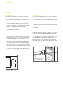
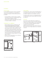
KICKPLATE
The upper right corner of any kickplate exceeding 3
3
/8" (86)
in height must be notched to allow for airow. Refer to the
illustration below.
Installation
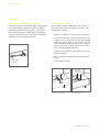
KICKPLATE CLEARANCE
It is possible to adhere a custom kickplate to the factory
kickplate. The height and thickness can vary, provided it
does not impede the door panel rotation. Refer to the
illustration below.
FRONT VIEW
DOOR PANEL
KICKPLATE
3
1
/8"
(79)
4" (102)
6"
(152)
3
3
/8"
(86)
Kickplate notch
2
3
/4" (70)
KICKPLATE
HEIGHT
FACTORY KICKPLATE
30
3
/8" (772)
TYPICAL PANEL
HEIGHT
4" (102)
TYPICAL
TOE KICK
34
1
/2" (876)
TYPICAL
PRODUCT
HEIGHT
3
1
/8" (79)
MAX DEPTH
1
3
/4" (44)
DEPTH
ADJUSTMENT
Toe kick area (side view)

coveappliance.com | 13
INSTALLATION
Installation
COMPLETION
1 Turn the water and electrical supply on.
2 For water softener models, refer to the Water Softener
section to adjust the water hardness, then proceed to
the next step.
3 Install all interior racks.
4 Run a Quick cycle and check for leaks.
5 Reverse the process to remove for inspection.
Water Softener
For water softener models only, a salt compartment is
located at the bottom of the interior. Refer to the illustration
below. Softener salt is available through an authorized Cove
dealer.
Prior to lling the salt compartment for the rst time, ll the
compartment with water. Water does not have to be added
with subsequent rells.
CAUTION
Do not add anything other than dishwasher salt to the
salt compartment.
To add softener salt:
1 Pull the lower rack forward and if necessary, turn the
lower spray arm away from the compartment cover.
2 Turn the cover counterclockwise to remove. It is normal
for the reservoir to contain water.
3 Fill the compartment completely with dishwasher soft-
ener salt.
4 Once full, clean any excess salt from the threads of
the salt compartment, then turn the cover clockwise to
secure.
SOFTENER SALT
COMPARTMENT
Softener salt compartment

14 | Cove Customer Care 800.222.7820
INSTALLATION
Water Softener
WATER HARDNESS
For water softener models only, use the test strip provided
and the chart below to determine the appropriate water
hardness setting. Refer to the chart below to determine the
water hardness setting.
SETTING HARDNESS
0 (Default) 0–4 gpg
1 5–6 gpg
2 7–8 gpg
3 9–11 gpg
4 12–13 gpg
5 14–15 gpg
6 16–17 gpg
7 18–19 gpg
8 20–22 gpg
9 23–24 gpg
10 25+ gpg
Setting user options:
1 Touch Cancel twice.
2 Touch and hold Options for approximately 3 seconds
until “User Set Up” appears on the display.
3 Touch Options multiple times to scroll to Water
Hardness.
4 Touch Enter to scroll or to select the desired setting.
5 Touch Cancel to exit user setup.

coveappliance.com | 15
Troubleshooting
Dishwasher does not operate.
• Verify power is on.
• Verify electrical power to the dishwasher and home
circuit breaker is on.
• Verify the child lock, Sabbath feature, and showroom
mode are not turned on.
Sub-Zero, Sub-Zero & Design, Sub-Zero & Snowake Design, Dual Refrigeration, The Living Kitchen, Great American Kitchens The Fine Art of Kitchen Design, Wolf, Wolf &
Design, Wolf Gourmet, W & Design, red colored knobs, Cove, and Cove & Design are registered trademarks and service marks of Sub-Zero Group, Inc. and its subsidiaries.
All other trademarks are property of their respective owners in the United States and other countries.
TROUBLESHOOTING
WARNING
Follow all city and state laws when storing, recycling or
discarding unused dishwashers.

2 | Atención al cliente de Cove 800.222.78200
LAVAVAJILLAS COVE
Contenido
3 Lavavajillas Cove
4 Especicaciones
7 Panel de la puerta
9 Instalación
15 Solución de problemas
Las características y especicaciones están sujetas a
cambios sin previo aviso. Visite coveappliance.com/specs
para obtener la información más actualizada.
Aviso importante
Para garantizar que este producto se instale y opere de
la forma más segura y eciente posible, tome nota de los
siguientes tipos de información resaltada en este manual:
AVISO IMPORTANTE señala la información que es especial-
mente importante.
PRECAUCIÓN indica una situación en la que se pueden
sufrir heridas leves o provocar daños al producto si no se
siguen las instrucciones.
ADVERTENCIA indica peligro de que se produzcan heridas
graves o incluso la muerte si no se siguen las precauciones.
AVISO IMPORTANTE: En toda esta guía, las dimensiones
entre paréntesis son milímetros, a menos que se especi-
que lo contrario.
AVISO IMPORTANTE: Los lavavajillas residenciales certi-
cados no están diseñados para establecimientos alimenti-
cios autorizados.
AVISO IMPORTANTE: Tenga cuidado al instalar y extraer la
unidad para evitar dañar el cable de alimentación eléctrica
(#827613).

coveappliance.com | 3
Información del producto
La información importante del producto, incluidos el modelo
y el número de serie de la unidad, se encuentra en la placa
de datos del producto. La placa de datos se encuentra
en la pared izquierda de la unidad. Consulte la siguiente
ilustración.
Si es necesario realizar algún servicio, póngase en con-
tacto con el Servicio certicado de fábrica de Cove y tenga
a mano el modelo y el número de serie. Para obtener los
datos del centro de Servicio certicado de fábrica de Cove
más cercano o si tiene preguntas acerca de la instalación,
visite la sección de contacto y servicio técnico en nuestro
sitio web, coveappliance.com, o bien, llame a la línea de
atención al cliente de Cove al 800-222-7820.
PLACA DE DATOS
Ubicación de la placa de datos
LAVAVAJILLAS COVE

4 | Atención al cliente de Cove 800.222.78200
ESPECIFICACIONES
23
5
/8" (600)
ANCHO DE LA ABERTURA
34
1
/
2
"
(876)
ALTURA DE
LA ABERTURA
VISTA SUPERIOR
VIST
A LATERAL VISTA FRONTAL
NOTA: Los tubos de retorno de
3
1
/2" (89) con acabados se podrán ver y se deben
ter
minar para que se ajusten a los gabinetes.
TÍPICO
DE
3
/4" (19)
GABINETE
CON MARCO
23
5
/8"
(600)
RELLENO
TUBO DE
RETORNO DE
3
1
/2" (89)
CON ACABADOS
GABINETES
SIN MARCO
23
5
/8"
(600)
TÍPICO
DE
3
/4" (19)
TUBO DE
RETORNO DE
3
1
/2" (89)
CON ACABADOS
24" (610)
PROFUNDIDAD MÍN.
DE LA ABERTURA
Dimensiones de abertura
LAVAVAJILLAS

coveappliance.com | 5
Requisitos eléctricos
La instalación debe cumplir con todos los códigos eléc-
tricos vigentes. Cualquier abertura en el gabinete contiguo
debe cumplir lo siguiente: la dimensión más larga de la
abertura no debe ser superior a 1
1
/2" (38). Los bordes de la
abertura deben ser lisos y redondos.
Ubique el suministro eléctrico en un gabinete contiguo
dentro del alcance del cable de alimentación eléctrica.
Consulte las siguientes ilustraciones. Se necesita un circuito
independiente que le suministre electricidad únicamente a
este electrodoméstico. Se puede requerir una toma o un
interruptor de circuito de fallos de conexión a tierra (GFCI,
por sus siglas en inglés), el que cumpla con los códigos
locales.
REQUISITOS ELÉCTRICOS
Suministro eléctrico 115 V CA, 60 Hz
Servicio Circuito dedicado de 15 amperes
Receptáculo Conexión a tierra de 3 clavijas
Cable de alimentación eléctrica 3'
(0.9 m)
E
E
UBICACIÓN
ELÉCTRICA
EN GABINETE
CONTIGUO
VISTA FRONTAL
5
1
/2" (140)
1
1
/2"
(
38
)
2" (51)
ZÓCALO
VISTA LATERAL
PARTE POSTERIOR
DE LA ABERTURA
Ubicación eléctrica
Guía eléctrica
INSTRUCCIONES PARA REALIZAR LA CONEXIÓN
A TIERRA
Este electrodoméstico debe ser conectado a tierra. En caso
de que se produzca un desperfecto o fallo, la conexión a
tierra reduce el riesgo de descarga eléctrica al proporcionar
un recorrido de menos resistencia para la corriente
eléctrica. Este electrodoméstico está equipado con un cable
que tiene un conductor de conexión a tierra de equipo y un
enchufe de conexión a tierra. El enchufe debe conectarse a
un tomacorriente adecuado instalado y conectado a tierra
de conformidad con los códigos y las ordenanzas locales.
ADVERTENCIA
La conexión incorrecta del conductor de conexión a
tierra de equipo puede resultar en un riesgo de des-
carga eléctrica. Verique con un electricista calicado
o representante de servicio si tiene duda de que el
aparato esté conectado correctamente a tierra. No
modique el enchufe provisto con el electrodoméstico.
Si no encaja en el tomacorriente, pida a un electricista
calicado que instale un tomacorriente adecuado.
PLACA DE DATOS
Ubicación de la placa de datos
ESPECIFICACIONES

6 | Atención al cliente de Cove 800.222.78200
Requisitos de plomería
La instalación debe cumplir con todos los códigos de plo-
mería vigentes. Cualquier abertura en el gabinete contiguo
debe cumplir lo siguiente: la dimensión más larga de la
abertura no debe ser superior a 1
1
/2" (38). Los bordes de la
abertura deben ser lisos y redondos.
La unidad tiene instalado de fábrica un bucle alto en la
tubería de drenaje. No retire la abrazadera del bucle alto.
Si es necesario, los tubos de drenaje se pueden extender
un máximo de 5'
(1.5 m).
Ubique el suministro de agua y drenaje en un gabinete
contiguo. Guíe el suministro de agua a través de la zona
sombreada que se muestra en la ilustración a continuación.
Conecte el suministro de agua al suministro doméstico de
agua caliente con una válvula de cierre de fácil acceso entre
el suministro y la unidad.
AVISO IMPORTANTE: Este electrodoméstico está diseñado
para conectarse a un suministro de agua caliente. El sumi-
nistro de agua no puede quedar expuesto a temperaturas
de congelación.
Purgue el suministro de agua antes de hacer la conexión nal
a la unidad. Esto eliminará cualquier residuo que pueda haber
quedado en la tubería al instalar el nuevo suministro de agua.
Conecte el tubo trenzado de la unidad al suministro de agua
doméstico con el accesorio provisto. Revise todos los acce-
sorios del suministro de agua para detectar fugas.
5
1
/2" (140)
1
1
/2"
(
38
)
2" (51)
ZÓCALO
VISTA LATERAL
PARTE POSTERIOR
DE LA ABERTURA
Guía del suministro de agua
ESPECIFICACIONES
REQUISITOS DE PLOMERÍA
Conexión de agua Tubos trenzados de 5' (1.5 m)
con accesorio de compresión
hembra de
3
/8"
Conexión de drenaje Tubos corrugados de 5' (1.5 m)
Presión De 35 a 140 psi(de 2 a 9.7 bares)
Temperatura de suministro máx. 140°F (60°C)
A página está carregando...
A página está carregando...
A página está carregando...
A página está carregando...
A página está carregando...
A página está carregando...
A página está carregando...
A página está carregando...
A página está carregando...
A página está carregando...
A página está carregando...
A página está carregando...
A página está carregando...
A página está carregando...
A página está carregando...
A página está carregando...
A página está carregando...
A página está carregando...
A página está carregando...
A página está carregando...
A página está carregando...
A página está carregando...
A página está carregando...
A página está carregando...
-
 1
1
-
 2
2
-
 3
3
-
 4
4
-
 5
5
-
 6
6
-
 7
7
-
 8
8
-
 9
9
-
 10
10
-
 11
11
-
 12
12
-
 13
13
-
 14
14
-
 15
15
-
 16
16
-
 17
17
-
 18
18
-
 19
19
-
 20
20
-
 21
21
-
 22
22
-
 23
23
-
 24
24
-
 25
25
-
 26
26
-
 27
27
-
 28
28
-
 29
29
-
 30
30
-
 31
31
-
 32
32
-
 33
33
-
 34
34
-
 35
35
-
 36
36
-
 37
37
-
 38
38
-
 39
39
-
 40
40
-
 41
41
-
 42
42
-
 43
43
-
 44
44


Sub-Zero DW2450WS Guia de instalação
- Categoria
- Máquinas de lavar louça
- Tipo
- Guia de instalação
- Este manual também é adequado para
em outras línguas
- español: Sub-Zero DW2450WS Guía de instalación
- français: Sub-Zero DW2450WS Guide d'installation
- English: Sub-Zero DW2450WS Installation guide
Artigos relacionados
-
Wolf 24 inch E Series Guia de instalação
-
Sub-Zero 5230780 Guia de instalação
-
-
Sub-Zero IC-36R Guia de instalação
-
Wolf OG30 Guia de instalação
-
Sub-Zero CG365C/S Guia de instalação
-
Sub-Zero DO30PM/S/PH Guia de instalação
-
-