
THERMADOR.COM
Installation
INSTRUCTIONS
Professional Custom Insert Hoods

THERMADOR.COM
Installation
INSTRUCTIONS
Table of Contents (English)................................................................3
Table de Matières (Français)............................................................22
Índice de Materias (Español)............................................................43
Models |
Modèles |
Modelos:
VCIN36GWS
VCIN42GWS
VCIN48GWS
VCIN54GWS
VCIN60GWS
Professional Custom Insert Hoods

Page. 3
This THERMADOR
®
appliance is made by
BSH Home Appliances Corporation
1901 Main Street, Suite 600
Irvine, CA 92614
Questions?
1-800-735-4328
www.thermador.com
We look forward to hearing from you!
Table of
CONTENTS
Safety ..................................................................................... 4
Important safety instructions .......................................... 4
Advance planning .................................................................. 6
Before you begin ............................................................ 6
General information ....................................................... 7
Installation instructions ........................................................... 8
Installation considerations............................................... 8
Electrical requirements ................................................... 9
Ductwork preparation .................................................... 10
Common ducting configurations..................................... 12
Choosing the correct blower .......................................... 13
Hood transition................................................................ 13
Preparing the ceiling cutout and housing ....................... 14
Custom insert installation with hood trims...................... 14
Blower motor installation ............................................... 16
Electrical wire connection................................................ 18
Make-Up air damper relay switch (optional) ................... 18
Remote control installation (optional) ............................ 19
Installing filters and grease trays..................................... 20
Installer checklist and service ................................................. 21
Installer checklist ............................................................. 21
Before calling service ...................................................... 21
Product data rating plate ............................................... 21
Service, parts, and accessories..................................back page
Safety
DEFINITIONS
9 WARNING
This indicates that death or serious injuries may occur as a
result of non-observance of this warning.
9 CAUTION
This indicates that minor or moderate injuries may occur as a
result of non-observance of this warning.
NOTICE: This indicates that damage to the appliance or
property may occur as a result of non-compliance with this
advisory.
Note: This alerts you to important information and/or tips.

Page. 4
Safety
9 IMPORTANT SAFETY INSTRUCTIONS
READ AND SAVE THESE INSTRUCTIONS
INSTALLER: Save these instructions for the local electrical
inspector’s use. Please leave these instructions with this
unit for the owner. Show the owner the location of the
circuit breaker or fuse. Mark it for easy reference.
OWNER: Read and save these instructions. Please retain
these instructions for future reference.
WARNING
If the information in this manual is not
followed exactly, a fire or explosion may
result causing property damage,
personal injury or death.
-- DO NOT store or use gasoline or other
flammable vapors and liquids in the vicinity
of this or any other appliance.
-- WHAT TO DO IF YOU SMELL GAS
• DO NOT try to light any appliance.
• DO NOT touch any electrical switch.
• DO NOT use any phone in your building.
• Immediately call your gas supplier from a
neighbor’s phone. Follow the gas
supplier’s instructions.
• If you cannot reach your gas supplier, call
the fire department.
-- Installation and service must be performed
by a qualified installer, service agency or the
gas supplier.
WARNING
Turn off power circuit at service panel and lock out
panel before wiring this appliance. Requirement: 120
VAC, 60 Hz, 15 A or 20 A for some models. Allow the
appliance to cool after the power has been turned off
before servicing the appliance.
WARNING
Automatically operated device
To reduce the risk of injury disconnect from power
supply before servicing.
WARNING
TO REDUCE THE RISK OF FIRE, ELECTRIC SHOCK,
OR INJURY TO PERSONS, OBSERVE THE
FOLLOWING:
• Use this unit only in the manner intended by the
manufacturer. If you have questions, contact the
manufacturer.
• Before servicing or cleaning unit, switch power off
at service panel and lock the service
disconnecting means to prevent power from
being switched on accidentally. When the service
disconnecting means cannot be locked, securely
fasten a prominent warning device, such as a tag,
to the service panel. Contact the manufacturer at
the address or telephone number listed on the
back page.
WARNING
DO NOT repair or replace any part of the appliance
unless specifically recommended in the manuals.
Improper installation, service or maintenance can
cause injury or property damage. Refer to this manual
for guidance. All other servicing should be done by a
qualified technician.
WARNING
ELECTRICAL SHOCK HAZARD
• DO NOT remove connections.
• DO NOT use an extension cord.
• Improper grounding can result in a risk of
electric shock.
• Failure to follow these instructions can result
in death, fire, or electrical shock.

Page. 5
9 IMPORTANT SAFETY INSTRUCTIONS
READ AND SAVE THESE INSTRUCTIONS
Grounding Instructions
This appliance must be grounded. In the event of an
electrical short circuit, grounding reduces the risk of
electric shock by providing an escape wire for the electric
current.
Be sure your appliance is properly installed and grounded
by a qualified technician. Installation, electrical
connections and grounding must comply with all
applicable codes.
If required by the National Electrical Code (or Canadian
Electrical Code), this appliance must be installed on a
separate branch circuit.
WARNING
To reduce the risk of fire or electric shock, DO NOT
use this appliance with any solid-state speed control
devices.
Safety Codes and Standards
This appliance complies with one or more of the following
Standards:
• UL 507, The Standard for the Safety of Electric Fans
• CSA C22.2 No. 113, Fans and Ventilators
It is the responsibility of the owner and the installer to
determine if additional requirements and/or standards
apply to specific installations.
CAUTION
Unit is heavy and requires at least two people
or proper equipment to move and install.
Hidden surfaces may have sharp edges. Use
caution when handling the appliance. Failure
to do so may result in property damage or
personal injury.
State of California Proposition 65 Warning:
: WARNING
This product can expose you to chemicals including
vinyl chloride, which is known to the State of California
to cause cancer and birth defects or other
reproductive harm. For more information go to
www.P65Warnings.ca.gov.
Never modify or alter the construction of the appliance.
For example, do not remove panels, wire covers or
brackets/screws.
CAUTION
For general ventilating use only. DO NOT use to
exhaust hazardous or explosive materials and vapors.
To reduce the risk of fire, use only metal ductwork.
Use a qualified installer.
Remove all tape and packaging before using the
appliance. Dispose of packaging in an environmentally-
responsible manner. Never allow children to play with
packaging material.
WARNING
TO REDUCE THE RISK OF FIRE, ELECTRIC SHOCK,
OR INJURY TO PERSONS, OBSERVE THE
FOLLOWING:
• Installation work and electrical wiring must be
done by qualified person(s) in accordance with all
applicable codes and standards, including fire-
rated construction.
• Sufficient air is needed for proper combustion and
exhausting of gases through the flue (chimney) of
fuel burning equipment to prevent back drafting.
Follow the heating equipment manufacturer's
guideline and safety standards such as those
published by the National Fire Protection
Association (NFPA), and the American Society for
Heating, Refrigeration and Air Conditioning
Engineers (ASHRAE), and the local code
authorities.
• When cutting or drilling into wall or ceiling, do not
damage electrical wiring and other hidden
utilities.
• Ducted fans must always be vented to the
outdoors.
• USE ONLY METAL DUCTWORK.
• DO NOT vent exhaust air in spaces with walls or
ceilings or into attics, crawl spaces or garages.
CAUTION
An outside fan is to be mounted behind louvers or in a
location where the entrance of drawn in water is
unlikely.

Page. 6
Advance planning
Before you begin
9 CAUTION
Before installing, turn power OFF at the service panel.
Lock service panel to prevent power from being
turned ON accidentally.
Parts included
• Metal transition with backdraft damper
• Stainless steel baffle filters
• Stainless steel grease trays
• Stainless steel filter spacers
• Side trims
• Blower adapter
• Fastener assortment*
* Hardware provided is for mounting through standard
thickness drywall or plaster into wood studs. Installers are
responsible to provide hardware for other types of
mounting situations.
Tools and parts needed
• Blower (refer to the Ventilation Planning Guide for
compatible blowers)
• Ducting as needed (refer to Equivalent Duct Lengths
for Commonly Used Transitions table)
• Aluminum tape (DO NOT use duct tape.)
• 1/2'' (13 mm) conduit if required (follow local codes)
• 1'' (25.4 mm) Strain relief
• Phillips screwdriver
• T-20 Torx head screwdriver
• 11/32'' nut driver or socket and ratchet
• Drill with 3/16'' (4.76 mm) drill bit
• Framing material (as necessary for framework)
• Circular saw or jigsaw
• Wire stripper
• Tape measure
• Protective work gloves
IMPORTANT: DO NOT throw away any packaging until
appliance is fully installed.
Optional accessories available for
separate purchase
Refer to www.thermador.com for more details.
• REMCPW – Built-in Remote Control Accessory
• EXTNCB25W – 25 ft. Remote and In-line Blower
Extension Cable
• WC8 - 8" Wall Cap
• WC10 - 10" Wall Cap
• RFPLT600P - Roof plate for use with 600 CFM Remote
Blower VTR630
• RFPLT1000P - For use with 1000 CFM Remote Blower
VTR1030 and 1300 CFM Blower VTR1330

Page. 7
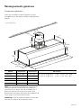
General information
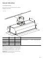
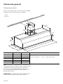
Overall dimensions
This model series features brushed stainless-steel filters,
LED lights, and side trims.
NOTE: Transition is centered horizontally. For optimal
performance, the hood should be mounted flush against
the back wall. In such installations, the rear trim piece is
not necessary. For installations of ½'' – 3'' (13 – 76 mm)
from the back wall, the rear trim piece can be used.
IMPORTANT: The hood needs to be centered over the
cooking surface for best performance.
Model Dimension A Dimension B Dimension C
VCIN36WS 32-3/8'' (822) 33-3/4'' (857) With rear trim piece: 7-3/8'' – 10-3/8'' (187 – 264)
VCIN42WS 38-3/8'' (974) 39-3/4'' (1,010) Without rear trim piece: 6-5/8'' – 9-5/8'' (168 – 245)
VCIN48WS 44-3/8'' (1,127) 45-3/4'' (1,162)
VCIN54WS 50-3/8'' (1,280) 51-3/4'' (1,315)
VCIN60WS 56-3/8'' (1,430) 57-3/4'' (1,467)
C
A
B
16
(424)
16
(424)
16
(424)
11/
16
"
6¼" (157)
6¼" (157)
6¼" (157)
7
(195)
11/
16
"
20
(554)
20
(554)
20
(554)
22"
(559)
22"
(559)
22"
(559)
12
(326)
12
(326)
12
(326)
11/
16
"
7
(189)
7
(189)
7
(189)
7/
16
"
dia. 10"
(254)
5/
8
"
inches (mm)

Page. 8
Installation instructions
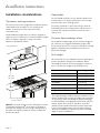
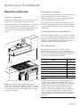
Installation considerations
Clearances and requirements
The custom insert unit is designed for installation inside a
custom-built hood assembly. It is for ducting to the
outside. It cannot be used in conjunction with a
recirculation unit.
Hood installation height above a cooktop, rangetop or
range can vary. To obtain the necessary installation height
above a cooktop, rangetop or range, consult the
appliance's installation manual.
NOTICE: The hood could incur some damage from heat if
a Thermador Professional
®
series range or rangetop is
operated with multiple burners at high settings under a
hood that is installed at minimum clearances while the
hood is turned off.
Hood width
The hood width should be no less than the width of the
cooking surface. For proper performance, the housing
must cover the entire cooking surface.
For proper performance, the hood must be centered
horizontally above the cooking surface. Where space is
not restricted, a wider hood can be used to increase
capture area.
Distance from cooking surface
The installation height ranges from a minimum height of
30'' (762 mm) to a suggested maximum height of 40''
(1,016 mm); however, it is necessary to follow the cooking
appliance manufacturer’s installation instructions for
proper hood height.
Unit weight
This vent hood is heavy. Adequate structure and support
must be provided in all types of installations. When
calculating the load for the housing support system, be
sure to consider the weight of the ventilation unit.
* Follow cooking appliance manufacturer’s
recommendations.
* 30" (762) –
40" (1,016)
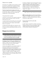
Electrical
Zone
7
(189)
7
(189)
7
(189)
7/7/7/
161616""
12
(326)
12
(326)
12
(326)
11/
16
"
inches (millimeters)
Description Weight
VCIN36WS 53 lb (24 kg)
VCIN42WS 63 lb (29 kg)
VCIN48WS 69 lb (31 kg)
VCIN54WS 79 lb (36 kg)
VCIN60WS 85 lb (39 kg)
Integral Blower VTN1090R 23 lb (11 kg)
Integral Blower VTN630W 11 lb (5 kg)
NOTICE:
The supplied weights address only the ventilation unit or
blower. Installer must account for weight of any materials
of construction when calculating the total dead weight
load of installation, including but not limited to: wall, tile,
mortar, plaster, brick, finishes, partitions, and other
similarly incorporated architectural and structural items.
It is the responsibility of the owner and the installer to
determine if additional requirements and/or standards
apply to specific installations.

Page. 9
Blower motors
Integral, In-line and Remote blowers are available through
your authorized Thermador
®
dealer. For local dealer
information, visit the Find a Dealer section of our website
at www.thermador.com.
The blower performance options will vary in cubic feet per
minute (CFM) and is dictated by the cooking surface, the
volume of air that needs to be moved and the length of
the duct run. Refer to the “Blower Motor Installation”
section for detailed blower motor information.
Support structure
Due to the weight of the hood, make sure the hood is
attached to all available wall studs.
Framing must be fastened together and to ceiling joists to
provide enough structural strength to support the weight
of the hood and internal blower, if applicable.
Wall framing should be, at minimum, made of 2"x 4"
lumber. Proper structural support is required to
accommodate the weight of the hood.
Electrical requirements
The unit requires a 120V AC, 60Hz. 15A branch circuit. The
VTR1330 blower in conjunction with a PHxxGWS requires
a 20 amp circuit breaker. The hood should only be
connected to a dedicated circuit (with ground) that has
been installed according to relevant regulations.
When connected to a GFCI-protected supply, Thermador
Professional
®
hoods are suitable for use in damp locations
that are protected from outside weather conditions and
not subject to saturation with water and other liquids, but
can be subject to moderate degrees of moisture (such as
an outdoor covered patio or lanai area). Refer to local
codes, NEC/CEC, and or the Authority Having Jurisdiction
(AHJ) for additional information.
Check your local building codes for proper method of
installation. In the U.S., this unit should be installed in
accordance with applicable local codes or, in the absence
of local codes, with the National Electrical Code, NFPA 70
or the Canadian Electric Code, CSA C22.1-02.
9 WARNING
The appliance must be grounded.
NOTE: The 25 ft. Remote and In-line Blower Extension
Cable accessory (EXTNCB25W) will only work for
distances up to 25 ft. The accessory cable must be
purchased separately. DO NOT use more than one Blower
Extension Cable per installation.
Electrical data
Data, including the model and serial number, is located on
the product data rating label inside the appliance, visible
after removal of the filter frame (see “Product Data Rating
Label”).

Page. 10
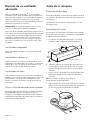
Ductwork preparation
Discharge direction
The exhaust air is discharged upwards through a duct or
directly through the outside wall into the open.
Ducting recommendations
Proper performance is dependent upon proper ducting.
Local building codes may require the use of make-up air
systems when using ducted ventilation systems greater
than specified cubic feet per minute (CFM) of air
movement. The specified CFM varies from locale to
locale. It is the responsibility of the owner and the installer
to determine if additional requirements and/or standards
apply to specific installations.
DO NOT USE FLEXIBLE DUCT; it creates back pressure/
air turbulence and reduces performance. Always install a
metal vent cover where the ductwork exits the house.
Hood must be vented to the outside of building only.
COLD WEATHER installations should have an additional
backdraft damper installed to minimize backward cold air
flow and a nonmetallic thermal break to minimize
conduction of outside temperatures as part of the
ductwork. The damper should be on the cold air side of
the thermal break. The break should be as close as
possible to where the ducting enters the heated portion
of the house.
MAKE-UP AIR: Local building codes may require the use
of make-up air systems when using ducted ventilation
systems greater than specified CFM of air movement. The
specified CFM varies from locale to locale. It is the
responsibility of the owner and the installer to determine if
additional requirements and/or standards apply to specific
installations.
To reduce risk of fire and to properly exhaust air, be sure
to duct air outside. Do not vent exhaust air in spaces with
walls or ceilings or into attics, crawl spaces or garages.
The unit cannot be used in conjunction with a recirculation
unit.
Thermador recommends not exceeding 50 ft
(15.24 m) equivalent of duct.
Keep duct runs as short and straight as possible. Elbows
and transitions fittings reduce air flow efficiency. Back to
back elbows and “S” turns give very poor delivery and are
not recommended.
A short, straight length of duct at the inlet of a remote
blower gives the best delivery.
Hoods are supplied with a 10" (254 mm) transition. A
locally supplied transition is required for other sizes.
Use the “Equivalent Duct Lengths for Commonly Used
Transitions” table to compute permissible lengths for duct
runs to outdoors.

Page. 11
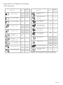
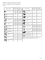
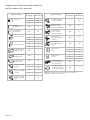
Equivalent Duct Lengths for Commonly
Used Transitions
Size (in)
Equivalent
Length (ft)
Size (in)
Equivalent
Length (ft)
61.2
610
8 0.7
10 0.6
3¼" x 10", straight N/A 1
3¼" x 10", Center
reverse elbow , right
N/A 25
3¼" x 14", straight N/A 0.7
3¼" x 10", Left
reverse elbow
N/A 15
3¼" x 10", Right
reverse elbow
N/A 25
612
62
8 6
8 2
10
10 2
65
62
2
5
8 3
8 2
2
2
10
10
3¼" x 10",
90° elbow , round
N/A 5
2’ long, 3¼" x 10" fl
ex N/A 20
3¼" x 10",
45° elbow , round
N/A 15
3¼" x 10", Flat elbow N/A 20
61
8 10
8 2
3¼" x 10", Roof jack
and shutter
N/A
65
610
NOTE: These commonly used installation parts can be purchased at a
local hardware store. Thermador does not manufacture all these parts.
Round wall cap
Round roof cap
3¼" x 10" to round
90° elbow ,
Duct Pie ce
3¼" x 10" Center
reverse elbow , left
15N/A
Round to 3¼" x 10"
3¼" x 10" to round
Round to 3¼" x 10"
90° elbow ,
Duct Pie ce
Smooth, straight
90° elbow , round
45° elbow , round

Page. 12
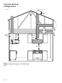
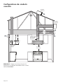
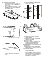
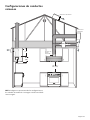
Common ducting
configurations
NOTE: The figure does not represent all configurations or
installation methods. The image is to be used as a guide
ONLY.
Back-draft
damper on
transition
Back-draft
damper on
transition
Back-draft
damper on
transition
Integral BlowerIntegral BlowerIntegral Blower
In-line BlowerIn-line BlowerIn-line Blower
Remote
Blower
Remote Blower
30" (762) –
40" (1,016)
Varies
12
(326)
12
(326)
12
(326)
11/
16
"
inches (mm)

Page. 13
Choosing the correct blower
It is recommended to use only Thermador blowers with
Thermador ventilation hoods. See the
Ventilation Planning
Guide for recommended blowers. Contact Customer
Service for additional options (see the back page for
contact information).
IMPORTANT: Cutting off a connector to the appliance,
blower, or to the extension cable kit will void the warranty.
Blower selection will vary based on the volume of air that
needs to be moved and the length and location of the
duct run. For long duct runs with multiple turns and
bends, consider using a more powerful blower. For the
most efficient air flow exhaust, use a straight run or as few
elbows as possible.
Integral blowers
These blowers are integrated into the hood at the time of
installation.
Remote blowers
Depending on preference and ducting situation, these
blowers can be mounted on the roof or exterior wall of the
home. An exterior installation may be more appealing to
reduce noise in the kitchen.
In-line blowers
To minimize noise in the kitchen, these blowers are
mounted along the duct line anywhere between the
kitchen and the exterior wall. If there is easy access to duct
line (in an attic, for example), this may be an appealing
option.
25 ft. remote and in-line blower extension
cable
The 25 ft. Remote and In-line Blower Extension Cable
(EXTNCB25W) is available to connect the hood to the In-
line and Remote Blowers for distances up to 25 ft.
Accessory cable must be purchased separately. DO NOT
use more than one Blower Connector Cable per
installation.
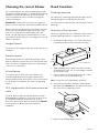
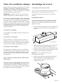
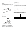
Hood transition
Discharge direction
The exhaust air is discharged upwards through a duct or
directly through the outside wall into the open.
The hood can be mounted on the wall only with a vertical
discharge.
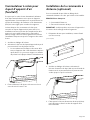
Assembly of the transition
Hoods are supplied with a 10" (254 mm) round transition.
A locally supplied transition is required for other sizes.
1. A minimum height clearance of 7-7/16'' (189 mm) is
needed above the hood for transition mounting.
2. Align mounting holes at base of transition over the
mounting holes of the 1/2'' (13 mm) flange located at
the top of the hood.
3. Fasten transition to hood using four (4) 1/4'' (6 mm)
sheet metal screws included with hood.
Note: Screws must not hinder damper operation.
4. Seal connection between transition and hood with
aluminum tape. DO NOT use duct tape. Ensure that
the connection is completely sealed.
5. Remove tape holding damper closed.
20 ¼"20 ¼"20 ¼"
(514)(514)(514)
7
(189)
7
(189)
7
(189)
161616
""
12
(322)
12
(322)
12
(322)
11/
16
"
7/7/7/
inches (millimeters)

Page. 14
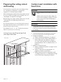
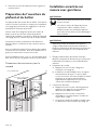
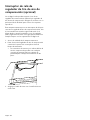
Preparing the ceiling cutout
and housing
The unit must be mounted to the surrounding housing.
See “Installation considerations” on page 8 for
suggestions on determining hood height.
When calculating the load for the housing support system,
be sure to include the weight of the ventilation unit. See
“Unit weight” on page 8 for unit weight.
Build housing in accordance with the dimensions noted in
“Ceiling Cutout and Supporting Stud Housing
Dimensions”.
For optimal performance, the hood should be mounted
flush against the back wall. In such installations, the rear
trim piece may not be necessary.
For installations of ½'' – 3'' (13 – 76 mm) from the back
wall, the rear trim piece can be used.
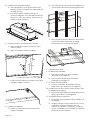
Ceiling Cutout and Supporting Stud
Housing Dimensions
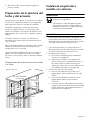
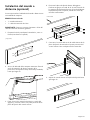
Custom insert installation with
hood trims
9 CAUTION
The hood requires at least two people to lift it
safely.
Hidden surfaces may have sharp edges. Use
caution when handling the appliance. Failure
to do so may result in property damage or
personal injury.
9 WARNING
To avoid electrical shock hazard, before installing,
switch power off at the service panel and lock the
panel to prevent the power from being switched on
accidentally.
1. Turn power OFF at the service panel. Lock service
panel to prevent power from being turned ON.
2. Prepare the ductwork.
a) Refer to “Ductwork preparation” on page 10.
b) Install metal transition with backdraft damper so
that the flap opens up toward the ceiling. If
necessary, install thermal break and additional
backdraft damper (refer to “Hood transition” on
page 13).
3. Build the housing framework.
a) Refer to “General information” on page 7 for the
model dimensions.
b) Refer to “Clearances and requirements” on
page 8 for clearance specifications.
c) Build housing framework for applicable model
according to dimensions in “Preparing the ceiling
cutout and housing” beginning on page 14.
⅝'' (16)⅝'' (16)⅝'' (16)
1½'' x 3½'' x 27-13/16''
(38 x 89 x 707)
1½'' x 3½'' x 27-13/16''
(38 x 89 x 707)
1½'' x 3½'' x 27-13/16''
(38 x 89 x 707)
56¼"
(1,429)
56¼"
(1,429)
56¼"
(1,429)
(448)(448)(448)
171717
55
//88""
16" (407)16" (407)16" (407)
0-3''
(0-76)
0-3''
(0-76)
0-3''
(0-76)
1½'' x 3½'' x 23⅜''
(38 x 89 x 594)
1½'' x 3½'' x 23⅜''
(38 x 89 x 594)
1½'' x 3½'' x 23⅜''
(38 x 89 x 594)
12
(322)
12
(322)
12
(322)
11/11/11/
161616
"
inches (mm)

Page. 15
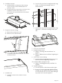
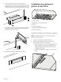
4. Install the hood trim.
a) Hold trim flush to the bottom of the housing.
Secure the trim to the hood with (20) x 3/8''
(9.5 mm) screws.
b) The back trim piece may not be necessary in some
installation scenarios where there is a ½''
(12.7 mm) or less space between the hood and
the back wall.
5. Prepare for the wire routing.
a) Remove the junction box cover.
b) Remove one circular knockout.
c) Install strain relief (not included) into one of the
circular knockouts.
6. Install the unit.
a) Install the custom insert inside the custom
housing.
b) Secure to the rear of the housing framework using
six (6) x 1'' (25.4 mm) mounting screws, as
indicated below.
c) Secure to the top of the housing framework using
eight (8) x 1'' (25.4 mm) mounting screws, 4 per
side.
7. Connect to the ductwork.
8. Install the blower motor.
a) Refer to “Choosing the correct blower” on
page 13.
b) Refer to “Blower motor installation” beginning on
page 16.
9. Connect the electrical wiring.
a) Connect wiring for applicable blower motor (see
blower instructions beginning on page 16).
10. Install hood filters and grease trays.
a) Refer to “Installing grease trays and filters” on
page 20.
11. Test the installation.
a) Test the operation of the blower and the lights.
b) Be sure to check for back-draft. With the blower
on high, close the windows and doors to the area
to ensure that fan does not cause back drafting in
any outlet vent for another appliance.
A
B

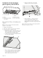
Page. 16
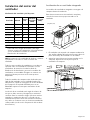
Blower motor installation
Blower and Circuit Breaker Ratings
9 CAUTION
To reduce the risk of fire and electric shock, install this
range hood only with the blowers listed in the
Ventilation Planning Guide.
NOTE: Cutting the plug of the blower will void the
warranty or eligibility for return or exchange.
All blower models are sold separately. Use only
Thermador blowers with these ventilation hoods. See the
Ventilation Planning Guide for recommended blowers.
Contact Customer Service for additional options.
All hood models are rated for 120V AC installed with a
blower listed in the table above, using a 15 amp
dedicated circuit breaker. The VTR1330 blower in
conjunction with a PHxxGWS requires a 20 amp circuit
breaker.
Blower selection will vary based on the volume of air that
needs moved and the length and location of the duct run.
For long duct runs with multiple turns and bends, consider
using a more powerful blower. For the most efficient air
flow exhaust, use a straight run or as few elbows as
possible (refer to “Ductwork Preparation”).
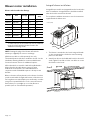
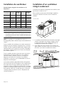
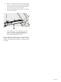
Integral blower installation
Integral blower models are integrated into the hood at the
time of installation. Integral blowers should be installed
after the hood is mounted to the wall.
For complete installation instructions see the instructions
supplied with the blower unit.
1. The blower is attached to the hood using weld studs
on the mounting plate. Guide the motor mounting
plate over the studs.
2. Attach four (4) nuts (included with hood) to the weld
studs. Tighten nuts with a 11/32'' nut driver to secure
the blower to the hood.
Blower SKU Voltage Current
Breaker
Amp
Remote VTR630 120 4.2 15
Remote VTR1030 120 5.7 15
Remote VTR1330 120 8.5 15 / 20
In-line VTI610 120 4.2 15
In-line VTI1010 120 5.7 15
Integral VTN630 120 4.2 15
Integral VTN1090 120 5.4 15
10⅞"
10⅞"
10⅞"
(275)
(275)
(275)
13⅛"
13⅛"
13⅛"
(335)
(335)
(335)
8¼"
(208)
8¼"
(208)
8¼"
(208)
18⅞"
18⅞"
18⅞"
(473)
(473)
(473)
inches (mm)

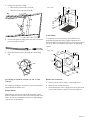
Page. 17
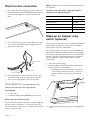
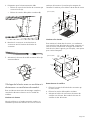
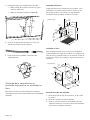
3. Prepare for the wire routing.
• Remove the junction box cover (A).
• Remove one circular knockout (B).
4. Connect the blower’s plug connector to the connector
present inside the hood.
5. Route the blower harness through the self-locking
clip.
Installing a remote blower or an in-line
blower
For complete installation instructions see the instructions
supplied with the blower unit.
Remote blower
Depending on preference and ducting situation, these
blowers can be mounted on the roof or exterior wall of the
home. An exterior installation may be more appealing to
reduce noise in the kitchen.
In-line blower
To minimize noise in the kitchen, these blowers are
mounted along the duct line anywhere between the
kitchen and the exterior wall. If there is easy access to duct
line (in an attic, for example), this may be an appealing
option.
Blower wire connection
1. Remove junction box channel covering the wires.
2. Remove one circular knockout.
3. Route the blower motor’s plug connector to the hood.
Connect the blower’s harness to the hood harness.
A
B
19"
(485)
2⅛"
(54)
10"
(254)
1¾"
(45)
20¾"
(527)
12⅞"
(327)
12⅛"
(308)
6½"
(165)
1⅞"
(48)
13⅝"
(346)
dia.
9⅞"
(251)
inches (mm)
12⅛"
(308)
14⅜"
(365)
⅞" (22)
1¾"
(44)
19⅛"
(486)
ø 9⅞"
(251)
12"
(305)
12⅞"
(327)
inches (mm)

Page. 18
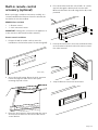
Electrical wire connection
1. Run a 120V AC, 15A circuit power cable or 20A for a
PHxxGWS product and the VTR1330 blower from the
service panel through one of the holes in the top
plate.
2. Connect black wire to power supply black wire, white
wire to power supply white wire and green wire to
green wire or bare wire.
3. Place all wiring connections inside the junction box
channel. Reinstall on the top plate. Ensure that the
wires are secure and that no wires are pinched.
EXTNCB25W 25 ft. remote and in-line
blower extension cable (optional)
Parts Included
• 1 – 25ft cable
• 2 – Adapter Cables (NOT NEEDED for all models)
Blower extension cable connection
The internal blower harness should be routed through the
knockout and secured with a 1'' (25.4 mm) strain relief.
The remote harness can then be connected to the blower
harness outside the unit.
NOTE: Cutting of the connector will void the warranty of
the appliance.
The blower extension cable is compatible with the
following In-line & Remote blowers:
Make-up air damper relay
switch (optional)
Local codes may require the use of an additional backdraft
and/or make-up air damper. Contact your local HVAC
professional for specific requirements.
This hood provides a relay switch to connect a Make-Up
Air Damper (120V max). Installations will vary according to
the location in the home where the unit is installed and the
damper used. Use the following illustration as guidance
for your installation. Always comply with local code
requirements.
1. Access the hood’s wiring.
2. Route the Make-up Air Damper harness through the
strain relief to the terminal block.
• The Make-up air kit hot and return connections
can use either terminal connection. There is no
polarity requirement for the two pin terminal
block.
3. Secure the ground wire with the green T-20 ground
screw.
White to white
Black to black
Green to green
or bare wire
Blower SKU
Remote Blower VTR630
Remote Blower VTR1030
Remote Blower VTR1330
In-line Blower VTI610
In-line Blower VTI1010

Page. 19
Built-in remote control
accessory (optional)
Before you begin, read these instructions carefully. It is
recommended that the Remote Control be wired to the
hood after the hood is installed.
REMCPW Parts Included
• 1 – Remote control
• 1 – 30 ft. extension harness
IMPORTANT: Cutting off a connector to the appliance or
to the extension cable kit will void the warranty.
Remote control installation
1. Prepare the wall (or similar surface) cutout for
installation as shown below
(view is shown facing wall).
2. Access the hood’s wiring. Route the 30 ft. extension
harness through the strain relief to the square
mounting clip until it clicks.
3. Route the 30 ft extension harness through the cutout
and connect the harness to the back of the remote
control bracket.
4. Press the bracket inside the cutout. Drill a ¼'' (6 mm)
tap hole through the bracket holes into the wall.
Mount the bracket to the wall using the four (4) screws
provided.
5. Hook up the wire harness connector inside the bracket
to the terminal on the back side of the remote control.
Use either terminal.
6. Snap the Remote Control into the bracket.
13
5
8
/
"
(346)
2
5
8
/
"
(65)
inches (mm)
inches (mm)

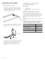
Page. 20
Installing grease trays and
filters
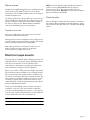
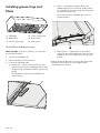
Install filters and grease trays
NOTE: DO NOT use burners, elements, or oven while
hood is disassembled.
1. Turn the fan and lights off.
2. Remove all plastic from hood pieces.
3. Insert in the following order:
a) Grease tray — Insert in rear tray. Grease trays
must be in place before installing the filters. Push
the grease tray in and down inside the grease tray
trough.
-- The small grease tray must be installed in the
center of hood
.
b) Filters — start with inserting the filter in the
middle and work out to the ends. Slide the filter
up, toward the front of the hood, then push down
on top of the grease tray
.
-- The 8" filter must be installed in the center of
hood at all times.
c) Filter spacers — If applicable, insert the filter
spacers on the left and right ends. Push up, slide
toward the front of the hood, then push in at the
bottom.
Reverse the above directions to remove the grease trays
and filters. Ensure filters are cool and grease has
congealed before removal.
(1) LED lights (2) Touch control panel
(3) Baffle filters (4) Grease trays
(5) Grease tray trough (6) Filter spacers
2
3
4
5
6
1
2
3
1
A página está carregando...
A página está carregando...
A página está carregando...
A página está carregando...
A página está carregando...
A página está carregando...
A página está carregando...
A página está carregando...
A página está carregando...
A página está carregando...
A página está carregando...
A página está carregando...
A página está carregando...
A página está carregando...
A página está carregando...
A página está carregando...
A página está carregando...
A página está carregando...
A página está carregando...
A página está carregando...
A página está carregando...
A página está carregando...
A página está carregando...
A página está carregando...
A página está carregando...
A página está carregando...
A página está carregando...
A página está carregando...
A página está carregando...
A página está carregando...
A página está carregando...
A página está carregando...
A página está carregando...
A página está carregando...
A página está carregando...
A página está carregando...
A página está carregando...
A página está carregando...
A página está carregando...
A página está carregando...
A página está carregando...
A página está carregando...
A página está carregando...
A página está carregando...
-
 1
1
-
 2
2
-
 3
3
-
 4
4
-
 5
5
-
 6
6
-
 7
7
-
 8
8
-
 9
9
-
 10
10
-
 11
11
-
 12
12
-
 13
13
-
 14
14
-
 15
15
-
 16
16
-
 17
17
-
 18
18
-
 19
19
-
 20
20
-
 21
21
-
 22
22
-
 23
23
-
 24
24
-
 25
25
-
 26
26
-
 27
27
-
 28
28
-
 29
29
-
 30
30
-
 31
31
-
 32
32
-
 33
33
-
 34
34
-
 35
35
-
 36
36
-
 37
37
-
 38
38
-
 39
39
-
 40
40
-
 41
41
-
 42
42
-
 43
43
-
 44
44
-
 45
45
-
 46
46
-
 47
47
-
 48
48
-
 49
49
-
 50
50
-
 51
51
-
 52
52
-
 53
53
-
 54
54
-
 55
55
-
 56
56
-
 57
57
-
 58
58
-
 59
59
-
 60
60
-
 61
61
-
 62
62
-
 63
63
-
 64
64


Thermador VCIN54GWS Guia de instalação
- Categoria
- Exaustores
- Tipo
- Guia de instalação
em outras línguas
- español: Thermador VCIN54GWS Guía de instalación
- français: Thermador VCIN54GWS Guide d'installation
- English: Thermador VCIN54GWS Installation guide
Artigos relacionados
-
Thermador PH60GS Guia de instalação
-
-
-
-
-
Thermador PH48HWS Guia de usuario
-
Thermador PH42GWS Guia de usuario
-
-
-
Outros documentos
-
Bosch HUI50351UC/01 Guia de instalação
-
Gaggenau AI 442 Guia de instalação
-
Fagor 60CFP-36IX User & Installation Manual (1.00 MB)
-
-
Broan B5936SS Guia de instalação
-
Wolf 5610509 Guia de instalação
-
Bosch HEI8054U/04 Guia de instalação
-
-
 Kenmore Elite 23355802110 Manual do proprietário
-
Sub-Zero PWC482418 Guia de instalação
