Thermador HMWN48FS Guia de instalação
- Categoria
- Exaustores
- Tipo
- Guia de instalação
Este manual também é adequado para

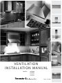
VENTILATION
INSTALLATION MANUAL
MODELS: HMWN30
HMWN36
HMWN48
LI3J1A Ed. 08/08

PLEASE READ ENTIRE INSTRUCTIONS BEFORE PROCEEDING.
INSTALLATION MUST COMPLY WITH ALL LOCAL CODES.
IMPORTANT: Save these Instructions for the Local Electrical Inspector’s use.
INSTALLER: Please leave these Instructions with this unit for the owner.
OWNER: Please retain these instructions for future reference.
Safety Warning: Turn off power circuit at service panel and lock out panel, before wiring this appliance.
Requirement: 120 V AC, 60 Hz. 15 or 20 A Branch Circuit
APPROVED FOR RESIDENTIAL APPLIANCES
FOR RESIDENTIAL USE ONLY
READ AND SAVE THESE INSTRUCTIONS
2

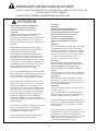
IMPORTANT SAFETY INSTRUCTIONS
Read All Instructions Before Using the Appliance.
READ AND SAVE THESE INSTRUCTIONS
WARNING
TO REDUCE THE RISK OF FIRE, ELECTRIC
SHOCK, OR INJURY TO PERSONS, OBSERVE
THE FOLLOWING:
A. Use this unit only in the manner intended by the
manufacturer. If you have questions, contact
the manufacturer.
B. Before servicing or cleaning the unit, switch
power off at service panel and lock service
panel disconnecting means to prevent power
from being switched on accidentally. When the
service disconnecting means cannot be locked,
securely fasten a prominent warning device,
such as a tag, to the service panel.
C. Installation Work and Electrical Wiring Must Be
Done By Qualified Person(s) In Accordance
With All Applicable Codes & Standards,
Including Fire-rated Construction.
D. Sufficient air is needed for proper combustion
and exhausting of gases through the flue
(chimney) of fuel burning equipment to prevent
back- drafting. Follow the heating equipment
manufacturers guideline and safety standards
such as those published by the National Fire
Protection Association (NFPA), the American
Society for Heating, Refrigeration and Air
Conditioning Engineers (ASHRAE), and the
local code authorities.
E. When cutting or drilling into wall or ceiling, do
not damage electrical wiring and other hidden
utilities.
F. Ducted systems must always be vented to the
outdoors.
CAUTION
FOR GENERAL VENTILATING USE ONLY. DO
NOT USE TO EXHAUST HAZARDOUS OR
EXPLOSIVE MATERIALS OR VAPORS.
CAUTION
To reduce risk of fire and to properly exhaust
air, be sure to duct air outside - do not vent
exhaust air into spaces within walls, ceilings,
attics, crawl spaces, or garages.
WARNING
TO REDUCE THE RISK OF FIRE, USE ONLY
METAL DUCT WORK.
Install this hood in accordance with all
requirements specified.
WARNING
To Reduce The Risk of Fire or Electric Shock,
Do Not Use This Hood With Any External Solid
State Speed Control Device.
OPERATION
a. Always leave safety grills and filters in place.
Without these components, operating blowers
could catch onto hair, fingers and loose clothing.
The manufacturer declines all responsibility in the
event of failure to observe the instructions given
here for installation, maintenance and suitable use
of the product. The manufacturer further declines
all responsibility for injury due to negligence and
the warranty of the unit automatically expires due to
improper maintenance.
This unit is manufactured for indoor use only. Do not use this unit outdoors.
3

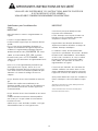
IMPORTANT SAFETY INSTRUCTIONS
Read All Instructions Before Using the Appliance.
READ AND SAVE THESE INSTRUCTIONS
Electrical requirements
IMPORTANT
Observe all governing codes and ordinances.
It is the customer’s responsibility:
To contact a qualied electrical installer.
To assure that the electrical installation is adequat e
and in conformance with National Electrical Code,
ANSI/NFPA 70 — latest edition*, or CSA Standards
C22.1-94, Canadian Electrical Code, Part 1 and
C22.2 No.0-M91 - latest edition** and all local
codes and ordinances.
If codes permit and a separate ground wire is used,
it is recommended that a qualied electrician
determine that the ground path is adequate.
Do not ground to a gas pipe.
Check with a qualied electrician if you a re not sure
range hood is properly grounded.
Do not have a fuse in the neutral or ground circuit.
IMPORTANT
Save Installation Instructions for electrical
inspector’s use.
The range hood must be connected with copper
wire only.
The range hood should be connected directly to the
fused disconnect (or circuit breaker) box through
metal electrical conduit.
Wire sizes must conform to the requirements of the
National E lectrical Code ANSI/NFPA 70 — latest
edition*, or CSA Standards C22.1-94, Canadian
Electrical Code Part 1 and C22.2 No. 0-M91 - latest
edition** and all local codes and ordinances.
A U.L. - or C.S.A. - listedconduit connector must be
provided at each end of the power supply conduit
(at the range hood and at the junction box).
Copies of the standards listed may be obtained from:
* National Fire Protection Association Batterymarch Park
Quincy, Massachusetts 02269
** CSA International 8501 East Pleasant Valley Road
Cleveland, Ohio 44131-5575
4

5
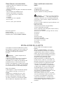
Parts In cluded with your Hood
t Hood Canopy Assembly without blower
t Grease lters
t Drip tray for each lter.
t Use & Care / Installation Instructions
t Fittings bag with:
t Drip trays holding brakets + plastic washers and
knobs
4 Washers
6 Drywall anchors
2 Hooks with regulating screws
6 Screws 5X35
4 Screws for transition
t 1 Transition withback draft damper
Option al accessory
Duct covers only for 30” and 36”
Ductless recirculation kit available only for HMWN30
HMWN36 model.
Parts Not Included with your
Hood
t Duct Tape
t 1/2" Conduit
t Wire Nuts
t Round Duct.
t Wiring clamp
t
CAUTION! Lamps are not supplied, use
ONLY 120 Volt, 50 Watt (maximum) 50°
halogen light made or a GU10 base,
suitable for use i n open luminarie .
t 4 #10 pan head wood screws for installation on
a bottom of a cabinet
Tools required
Flat blade and Phillips screwdrivers
Pencil and tape measure
Metal snips (in some applications)
Electric drill
Saw (saber or keyhole)
Pliers
Level
Caulking
Flashlight
Wire s
tripper
Safety glasses
Gloves
Step ladder
INSTALLING THE HOOD
t For the most ecient air flow exhaust, use a
straight run or as few elbows as possible.
CAU TIO N: Vent unit to outside o f
building, only.
t Two people are necessaryfor installation.
On average 2 hours are necessary to complete
installation (without considering cut to be done
on wall and or on cabinet, installation of ducts ,
conduit and electrical connections to the mains) .
installation steps:
11 installation steps are required for both
installation methods
Wall mount installation steps or in alternative
Cabinet installation
t The hood is tted with Screws and Drywall
Anchors suitable for most surfaces, consult a
Qualied Installer, check if they perfectly f it with
your cabinet/wall.
t Do not use ex ducting.
t COLD WEATHER installations should have an
additional backdraft damper i nstalled to
minimize backward cold air ow and a
nonmetallic thermal break to minimize
conduction of outside temperatures as part of
the ductwork. The damper should be on the
cold air side of the thermal break.
The break should be as close as possible to
where the ducting enters the heated portion of
the house.
t Make u
p
air: Local building codes may require
the use of Make-Up Air Systems when using
Ducted Ventilation Systems greater than
specied CFM of air movement.
The specied CFM varies from location to location.
Consult your HVAC professional for specic
requirements in your area.
t
3 prong plug
t
Blowers
See sections for integral ventilator installation and remote
ventilator installtion for more blower details.

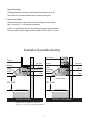
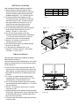
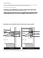
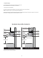
30” to 36”
* Charcoal lters
Lam p
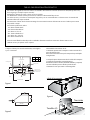
Round duct
Ceiling
Hood
Blower
Transition
Filter
VERTICAL DISCHARGE
30” to 36”
* Optional accessory - Ductless recirculation kit
* Only for 30” and 36” using integral blower VTN600F
Lam p
Ceiling
Hood
Blower
Transition
Filter
*Deector
RECIRCULATING
*Charcoal lters
Examples of possible ducting
6
t Typical installation
The height from the countertop to the bottom of the hood is 30” to 36”.
These hoods are not recommended to be used over indoor grills.
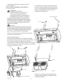
1. Choose vent options
The hood is designed to be used for vertical discharge as shown below.
Note: see also Fig. 1-2-3 for Cabinet preparation.
Install a 1/2” conduit from the service panel long enough to reach the hood
once it is installed. Power supply must be rated for 120 VAC, 60Hz. 15 or 20 A.

eceiPtcuD
10" round
to 8" roun d 5 ft.
Round , 1 ft.
straight (per foot
length)
3-1/4" x 10" 1 ft.
3-1/4" x 12 " (p er f oot
straight length)
8" Di a. 17 ft.
90° elbow 10" Dia. 24 ft .
8" Di a. 10 ft.
45° elbow 10" Dia. 14 ft .
3 -1⁄4" x 12" 15 ft.
3-1/4" x 10" 14 ft.
90° elbow
3-1/4" x 10" 8 ft.
3-1/4" x 12" 9 ft.
45° elbow
3-1/4" x 10" 33 ft.
3-1/4" x 12" 36 ft.
90° at elbow
10"round transition
to 3-1/4" x 10" or
3-1/ 4" x 12" 9 ft.
3-1/4" x 10" or
3-1/4" x 12" to
10" round transiti on 6 ft.
10" round to 3-1/4" x 10" 16 ft.
3-1/4" x 12" transition 13 ft.
90° elbow
3-1/4" x 10" 9 ft.
3-1/4" x 12" t o 10" round 8 ft.
transiti on 90° elbow
Roun d 8" Dia. 32 ft.
wall c ap 10" Dia. 41 ft.
wi th d a mp e r
3-1/4" x 10" 24 ft.
3-1/4" x 12" wall cap 26 ft.
wi th d a mp e r
Round 8" Dia. 44 ft.
roof cap 10" Di a. 56 ft .
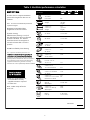
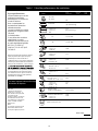
Use this chart to compute maximum
permissable lengths for duct runs to
outdoors.
Note:
Do not exceed maximum permissable
equivalent lengths!
Maximum recommended duct
length for these hoods: 150 feet
Fl exible ducting:
If exible metal duct ing is used, all
the equivalent feet values in the table
should be doubled. The flexible
metal duct should be straight and
smooth and extended as much as
possible.
Do NOT use exible plastic ducting.
To t a l D u c t R u n
Note:
Any home ventilation system, such as a
gas furnaces, gas water heaters and other naturally
vented systems. To minimize the chance of interruption
of such naturally vented systems, follow the heating
equipment manufacturer’s guidelines and safety
standards such as those published by NFPA and ASHRAE.
*Hoods are supplied with a 10"
round transition. A locally
supplied transition is required
for other sizes.
Note:
Outlet on top of hood is
8-1/8" x 8".
Table 1. Ventilator performance calculation
7

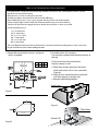
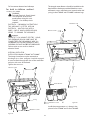
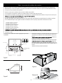
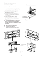
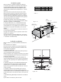
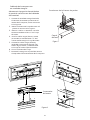
1. Prepare duct and conduit cut outs, see gures
1 and 2 as needed.
22
23-1/8”
Transition
Screws (4)
a. Place the transition piece over the hood
outlet and secure with 4 screws provided.
(Figure3)
b. Wrap all joints (metal transition and hood)
with duct tape for an airtight seal.
c. Remove tape holding damper.
Assembly of the 10” transition:
The transition supplied with the hood mounts to
the top.
Do not install transition until hood is
xed on cabinet or wall.
2.
Figure 3
Hood outlet
8
TABLE 2. DUCTWORK INSTALLATION GUIDELINES
For safety reasons, ducting should vent directly outdoors (not into an attic, underneath the house, into the
garage or into any enclosed space).
Keep duct runs as short and straight as possible.
Duct ttings (elbows and transitions) reduce air ow efciency.
Back to back elbows and “S“ turns give very poor delivery and are not recommended.
A short straight length of duct at the inlet of the remote blower gives the best delivery.
Transition to duct from the integral blower to remote duct transition as close as possible.
In order opreference, use:
1st. 10” round duct
2nd. 8” round duct
3rd. 3-1/4” x 14” duct
4th. 7” round duct
5th. 3-1/4” x l0” duct
6th. 6” round duct
The use of exible metal round duct should only be used when no other duct tting exists. Limit use to short
lengths
and do not crush when making corners.
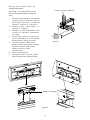
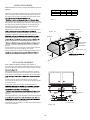
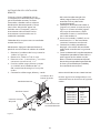
Figure 1
Figure 2
10-1/2
5- 7/8”
X
X
36”
30”
48”
2-3/4”
4-9/16”
10-9/16”
Model

HOOD W IDTH DIM. "W " DIM. "K " DIM. "Z"
30" 29 - 1/8" 2 - 1/2" 7 - 1/16"
36" 35 - 1/16" 2 - 1/2" 7 - 1/16"
48" 47 - 1/16" 2 - 1/2" 7 - 1/16"
Table 3
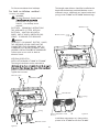
Side slot x 4
Figure 4b
Figure 4a
9
Wall Mount Installation
Note: see below if cabinet installation is preferred
3. After the hood installation height has been
determined draw a horizontal line at a distance
above the cooktop equal to the desired hood
installation height plus 7- 1/2”. See also Figure 4a.
4. Find the centerline of the cooktop. Draw a
vertical line along this centerline up to the hori-
zontal line drawn in step 1 and draw a vertical
line right and left at a distance of12-5/8” to
determine the mounting location of the
mounting hooks shipped with the hood.
5. Fit two mounting hooks on the wall to hang the
hood through the provided slots (2 wall
anchors + 2 hooks + 2 screws 5x35).
6. Run 10” Duct, long enough to reach the
transition once the hood has been installed plus
1 1/2” inch to connect ductwork. Fix Duct to
transition with screws and seal withtape.
7. Remove 1 of 2 knockouts and install 1/2”
conduit connector in j-box.
8. Hang the hood and adjust its position through
the screws on the hooks.
9. Fix the hood to 4 additional point, 2 on
upperside, 2 on lower side (use 4 wall anchors
+ 4washers + 4 screws 5x35).
Cabinet Installation:
Note: See above if wall mount installation is preferred
Note: Distances on Table 3.3.
Find the centerline of the cabinet bottom. Draw a line
along this centerline from rear to front of the cabinet.
See also Figure 4b.
4. Draw two lines, one at a K distance from the wall,
the other one at a Z distance from the previous line.
Mark 4 points, two along each line at a distance of
half W from the center line, to determine the screw
locations.
5. Fit 4 screws on cabinet bottom do not tighten
completely but leave a space of about 1/2” from
cabinet bottom surface and head screws.
6. Run 10” Duct, long enough to reach the transition
once the hood has been installed plus1 1/2” inch for
connect ductwork.
7. Remove 1 of 2 knockouts and install 1/2”conduit
connector in j-box.
8. Hang the hood on screws through side slots provided
on hood top. Tighten the four screws. Note: If possible
x the hood on the wall at 4 additional point (2 on
upper side, 2 on lowerside).
9. From the inside of the cabinet attach the transition
on upper outlet.
Center Hole

Fix Ducttotransitionand seal withtape.
For both ins tallation method :
10.Wiring the HOOD:
WARNING:
Electrical Shock Hazard
Turn o power at the service
panel before wiring this unit.
120 VAC, 15 or 20 Amp circuit
required.
ELECTRICAL GROUNDING INSTRUCTIONS
THIS APPLIANCE IS FITTED WITH AN
ELECTRICAL JUNCTION BOX WITH 3
WIRES, ONE OF WHICH (GREEN/YELLOW)
SERVES TO GROUND THE APPLIANCE.
TO PROTECT YOU AGAINST ELECTRIC SHOCK,
THE GREENAND YELLOW WIRE MUST BE
CONNECTEDTO THE GROUNDING WIRE IN
YOURHOME ELECTRICALSYSTEM,AND IT MUST
UNDERNO CIRCUNSTANCESBECUTORREMOVED
.
Failure to do so can result in death or
electrical shock.
10
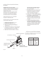
To Avoid
WARNING:
INTEGRAL VENTILATOR
INSTALLATION Models VTN600F & VTN1000F
The Integral ventilator can be mounted to
discharge air as show on gure 3 and 4b at page 9.
It must be xed through the slots of the ventilator
and pins with nuts of the hood.
Tighten the two nuts.
Motor Bracket
Motor Bracket
Spring
Spring
Machine screws
Machine screws
Millimetric nuts
Millimetric screws
Millimetric screws
Millimetric nuts
Figure 5a
Figure 5b
Install these components as is shown in the
picture 5a for VTN600F and 5b for VTN1000F.
The integral motor blowers should be installed to the
hood with the hardware provided (Machine screws,
millimetric screws, millimetric nuts, motor bracket and
spring) in the VTN600F and VTN1000F hardware bags.

11
Wiring the HOOD with an
Integral Ventilator:
Figure 7
Motor Connector
Warning: Turn o electricity at
the service panel before wiring the
unit.
1. Connect the Integral Ventilator
molex plug connector to the
connector present inside the
hood as shown in Figure 6.
2. Remove the j-box cover as
shown in Figure 7.
3. Remove 1 of 2 knockouts and
install 1/2” conduit connector
in j-box.
4. Run black, white, and green
wires (#14 AWG) in 1/2”conduit
from power supply to j-box.
5. Connect black, white, and
green wires from power supply
to black, white, and green/
yellow wires in j-box
respectively.
6. Close j-box coover.
7. Turn power on at service panel.
Check operation of the hood.
Power supply conduit
Figure 6

12
REMOTE VENTILATOR
INSTALLATION
HMWN30/36/48 Series Hood:
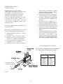
Figure 8
Connector in the
internal body panel
ELECTRICAL PIGTAIL DETAILS
The pigtail is congured to be connected
as is described in the following table.
FUNCTION COLOR
Speed 1 Red
Speed 2 Blue
Speed 3 Orange
Speed 4 Brown
Common White
The hood is designed to work with
Thermador’s remote and in line
ventilator rated with a maximum
corrent absorbtion of 8.5 Amp.
(see list under paragraph “Parts Not
Included with your Hood”) For
installation instructions see the
instructions supplied with the
ventilator unit.
Wiring the Hood with a Remote or in
line Ventilator:
Warning: Turn o electricity at the
service panel before wiring the unit.
1. Remove the j-box cover as shown
in Figure 8.
2. Remove cover T from the j-box.
3. Remove the 2 knockouts and
install 1/2” conduit connectors.
4. Run black, white, and green wires
(#14AWG) in 1/2” conduit
5. Connect black, white, and green
green wires from power supply
to black, white and green/ yellow
wires in j-box respectively.
6. Connect wire clamp to “pigtail” as
shown in Figure 12. Insert “pigtail”
wire into j-box and x wire clamp
to j-box using nut supplied with
clamp V.
7. Run ve wires (14AWG) in 1/2”
conduit from the remote blower
to the second conduit connector.
8. Connect the wires coming from
pigtil to the wires from external
blower according with the following
table.
9. Close junction box cover. Check
that all ligth bulbs are secure in
the soclets. Install lters. Turn
power on at service panel, and
check ligths and blower operation
per Care & Use section of this manual.

13
Final installation steps
11. Install grase lters, lamps and drip trays as
desripbed in the Care & Use section of this
manual.
Note: Lamps are not supplied, use ONLY 120 Volt,
50 Watt (maximum) 50º halogen light made for
GU10 base, suitable for use in open luminarie.
Turn power on at service panel.
Check operation of the hood.

IMPORTANTES INSTRUCTIONS DE SÉCURITÉ
ATTENTION
14
VEUILLEZ LIRE ENTIÈ REMENT CES INSTRUCTIONS AVANT DE PROCÉDER DE
L’UTILISATION DE VOTR E APPAR E IL.
VEUILLEZ LIRE ET CONSERVEZ SOIGNEUSEMENT CES INSTRUCTIONS
POUR RÉDUIRE LE RISQUE D’INCENDIE, DE
CHOC ÉLECTRIQUE OU DE BLESSURES,
VEUILLEZ OBSERVER LES INDICATIONS
SUIVANTES :
A.N’utiliser l’appareil que conformément aux
ins tructions du constructeur: ne pas se
conformer aux ins tructions peut s’avérer dangeu-
reux et annuler la garantie. S i vous avez des
ques tions, n’hés itez pa s à pre ndre conta ct ave c le
fa brica nt.
B. Ava nt toute inte rvention s ur votre a ppa reil,
mettez le bouton d’allumage en position OFF.
Veillez à toujours débrancher le câble
d’alimentation électrique avant de procéder à
toute réparation ou nettoyage de votre appareil.
Lorsqu’il n’est pas possible de débrancher le
câble d’alimentation électrique, veillez a ins taller
sur le tableau de commande (par exemple), une
signalétique d’avertissement bien visible, telle
qu’une étiquette de couleur rouge ou jaune
contenant des indications de sécurité.
C.Les Travaux d’installation de l’appareil, installa-
tion éle ctrique inclue, doivent être réalis és pa r du
personnel qualifié, ceci de conformité avec les
normes et diverses règlementations en vigueur.
D. A fin d’évite r tout re tour de fumé e s ou a utre s
vapeurs de cuisson, il est nécéssaire qu’il existe
un flux d’air suffisant passant au travers de la
hotte. Ob
servez les ins tructions du fabricant de
votre appareil de cuis ine (gaz ou électrique) tels
que ceux publié s pa r la Na tiona l F ire Prote ction
Association (NFPA), the American Society for
Heating, R efrigeration and Air conditioning
E ngineers (AS HR AE ), ainsi que la réglementa-
tion locale de votre lieu de rés idence (lieu où es t
utilis é l’appareil).
E.Lorsque vous perforez ou effectuez une rainure
dans un mur, veillez à ne pas endommager
l’ins tallation électrique, ains i que tout autre
ins tallation qui s’y trouve occulte.
F.Les conduits de ventilations doivent toujours
aboutir à l’extérieur de votre résidence.
ATTENTION
PRUDENCE
APPAREIL DESTINÉ UNIQUEMENT À DES
FINS DE VENTILATION GÉNÉRALE EN
USAGE DOMESTIQUE. AFIN D’EVITER TOUT
RISQUE D’EXPLOSION, NE PAS UTILISER
POUR VENTILER OU EXTRAIRE DES
VAPEURS OU FUMÉES PROVENANT DE
SUBSTANCES DANGEREUSES OU EXPLO-
SIVES .
PRUDENCE
Afin de réduire tout risque d’incendie et d’extraire
correctement les fumées et vapeurs, veillez à
brancher les conduits de la hotte vers l’extérieur
de votre résidence. Ne pas éva
cuer les fumées
et vapeurs de cuisine vers les colonnes sèches,
les espaces existant entre deux murs, les
espaces sous plancher ou des greniers.
ATTENTION
POUR R ÉDUIRE LE R ISQUE D’INCE NDIE,
LORS DE L’INSTALLATION DE CONDUITS DE
RACCORDEMENT ET D’EXTRACTION,
N’UTILIS ER QUE DE S CONDUITS MÉTAL-
LIQUES.
Installer la hotte en suivant toutes les indications
et spécifications nécéssaires et réglementaires.
ATTENTION
Afin d’éviter tout risque d’incendie ou de choc
électrique, ne pas utilis er cet appareil avec un
dispositif de programation ou de contrôle de la
vitesse de fonctionnement.
OPÉRATION
a. Ne jamais re tire r les grilles d’écoulement ou
les filtres à graisses.
S ans ces dispositifs, les ventilateurs peuvent
attraper au vol certaines parties de votre corps
(cheuveux, doigts ) ou de vos vêtements.
Le fa brica nt décline toute res pons a bilité da ns le
cas où les instructions d’installation, entretien et
utilisation, fournies avec l’appareil ne seraient
pas obs ervées.
Le fa bricant déc line éga lement toute res pon-
sabilité relative aux blessures produites à la suite
de négligences de la part de l’utilisateur et
signale que la garantie de l’appareil ne sera plus
valable dans le cas où l’appa reil n’es t pas
correctement entretenu et/ou répa ré.

IMPORTANTES INSTRUCTIONS DE SECURITÉ
15
Spécications pour l’installation élec-
trique
IMPORTANT
Observez toutes les normes et réglementation en
vigueur.
Il est de la responsabilité du client :
De faire ins taller l’appareil par un électricien dument
qualifié.
De s’ass urer que que l’ins tallation électrique es t
adpatée au branchement de l’appareil et qu’elle est
conforme á la réglementa tion électrique na tionale
(National E lectrical Code),
ANSI/NFPA 70
– latest
edition, ou CSA S tandarts
C22.1-94
, Canadian
Electrical Code, part 1 et
C22.2 No M91
– latest
edtion** ainsi que toute norme et réglementation locale
en vigueur.
Dans le cas où la réglementation permette l’usage
d’une ligne de terre séparée, et dans le cas où
l’ins tallation électrique du lieu le permet, il es t nécés -
saire d’avoir recours à un électricien qualifié afin qu’il
détermine si le chemin de cablâge à la terre est
adéquat
.
Ne pas brancher la terre à une bouteille ou citerne de
gaz.
Veuillez faire vérifie r votre ins ta lla tion pa r un
électricien qualifié s i vous n’êtes pas abs olument s ur
que le branchement à la terre de votre appareil est
correctement faite.
Ne pas brancher la terre à une bouteille ou une citerne
de gaz.
Veuillez consultez un technicien dûment qualifié s i
vous n’êtes pas sûr que la hotte est correctement
branchée à la terre.
Veillez à ne pas avoir de fusibles installés s ur la ligne
d’alimentation neutre ou sur la ligne de terre
IMPORTANT
Conservez le présent instructif pour votre
Inspecteur Local d’É lectricité.
Les fils électriques avec lesquels la hotte sera
branchée au réseau électrique doivent être
uniquement composés de cuivre.
L’a ppa reil devra être branché directement au
disjoncteur ou tableau de fusibles au moyen de
conduits électriques métalliques.
Le calibre des câbles de branchement doit
respecter les spécifications de la norme « National
Electrical Code » AINSI/NFA70 – latest edition*,
ou de la CSA** Sandarts C 22 1-94, Ca nadian
E lectrical C ode Part 1 and C 22. 2 No 0-M91 –
latest edition, ansi que toutes les normes et
réglementa tions en vigueur.
Il est nécéssaire d’installer des connexions de
conduits conformes aux normes A UL ou CSA
chaque extrémité du branchement (au niveau de
l’appareil et au niveau de la boîte de connexion).
(Vous pouvez obtenir des copies des standarts et
normes électriques ci-dessu mentionnés auprès
de :
*National Fire Protection Association, Batterymarch Park
Quincy, Massachussets 02269
**C S A International 8501 E as t P leasant Valley R oad
Cleveland, Ohio 44131-55
75.)
VEUILLEZ LIRE ENTIÈ REMENT CES INSTRUCTIONS AVANT DE PROCÉDER
À L’UTILISATION DE VOTRE APPARE IL.
VEUILLEZ LIRE ET CONSERVEZ SOIGNEUSEMENT CES INSTRUCTIONS

16
INSTALLATION DE LA HOTTE
Pièces fournies avec votre hotte.
t Cloche de hotte avec ventilateurs pré-installés.
t Filtres à graisses.
t G rille d’écoulement.
t Molettes de fixation des grilles d’ecoulement et boutons
en plastique.
t Une connexion de ventilation ronde.
t Manuels d’installation et d’entretien.
t Un S achet d’accessoires contenant:
t 4 rondelles.
t 6 chevilles.
t 2 crochets avec visse réglables.
t6 visses 5x35.
t4 visses 2,9,6,5, pour connexion
Accessoires optionnels
Couvre-conduits
Un kit de recyclage d’air sans conduit est
disponible pour le modèle HMWN30 HMWN36
Pièces non fournies avec votre
hotte :
tJoint de conduit.
tConduit de 1/2".
tEcrous de connexion électrique.
tAgrafes / fixations de câblage électrique
ATTENTION : Les lampes ne sont pas fournies,
UTILISER UNIQUEMENT des lampes hallogènes de
120 VOLTS d’une puissance de 50 Watts (maximum)
à 5 0 d e g r é s o u à b a s e G U 1 0 , a d a p té e à l ’ u ti l i s a ti o n e n
luminaire ouvert.
t4 visses t1 0 à bois à tê te fra is é e pour ins ta lla tion s u r le
fond d’un meuble.
Outils nécéssaires :
tTournevis pla t e t tounevis de type P hilips.
tC rayon et décimètre (un mètre).
tPinces coupantes pour métal (pour certaines tâches)
tUne perceuse électrique
tUne Scie (scie sauteuse ou de type trou de serrure).
tDes pinces
tUn niveau
tUn burin
tDu ruban isolant
tUne lampe électrique
tUne pince à dénuder les câbles
tDes lunettes de sécurité
tDes gants
tUne échelle
tNe pas utiliser de conduit d’évacuation
flexibles.
tBASS
ES TEMPERATURES: Il est recom-
mandé d’installer un réducteur de connexion
supplémentaire, afin de réduire les éventuels
retours d’air ainsi qu’un amortisseur thermique
non metallique (joint non metallique au niveau
des réducteurs et connexions) afin de
minimiser l’échange de température
intérieure/extérieure. Le réducteur devra être
installé du côté « extérieur » de l’amortisseur
thermique, lequel doit se trouver le plus proche
pos s ible du point où le conduit d’èva cua tion
entre dans la zone chauffée de la maison.
t Systèmes de ventilation : La réglementation
en vigueur dans votre lieu de résidence peut
exiger l’utilisation de sys tème de ventilation
rés identiel additionnel lorsque vous utilis ez
des appareils de ventilation/extraction d’air qui
requièrent l’ins talla tion de conduits
d’èvacuation et dont la puissance est supéri-
eure aux spécifications CF M de courants d’air.
Les normes et spécifications CFM varient
selon le lieu de résidence : cons ultez votre
professionnel HVAC pour connaître les normes
et spécifications applicables à votre lieu de
rés idence.
tPour obtenir un maximum d’éfficacité en extrac-
tion de fumées et vapeurs de cuis son, utilis er un
conduit le plus droit pos s ible, a
vec le minimum
de coudes et autre type de connexions
poss ibles.
PRUDENCE : ventiler uniquement vers
l’extérieur du bâtiment.
tIl faut une personne pour réaliser l’installation.
tIl faut en moyenne 2 heures pour réaliser
l’ins ta lla tion ( s a ns c ompte r le s a jus te me nts qu’il
peut falloir réaliser au niveau du mur ou du
meuble, ni l’installation des conduits d’èvacuation
ou celle des conduits électriques qui permettront
le raccordement au réseau électrique principal).
Etapes de l’installation :
tI l faut compter 11 é ta pes d’ins ta lla tion quelque
soit la méthode envisagée: sur mur ou sur
meuble.
tL’appareil es t accompagné de visses et de
chevilles adaptées à la plupart des surfaces
pos sibles d’ins tallation, nénamoins, veuillez
consulter un technicien ou insstallateur qualifié
afin de vérifier leur adéquation à votre surface

30” a 36”
*Fitres à charbon
Conduit d’extraction rond
Ventilateur
Décharge verticale
30” a 36”
Ventilateur
Transition
Recyclage
*Flitre à charbon
Exemples de possibles types d’extraction/evacuation
17
Installation typique
La hauteur entre le plan de travail de votre cuisine et la ligne inférieure de la hotte soit osciller entre 24 et 30 pouces.
Il n’est pas recomandé d’utiliser ce type de hotte aspirante au-dessus d’un grill d’interieur.
1.Choisissez le type de ventilation désirée.
Note: voir également Fig. 1-2-3 pour la préparation de l’installation sur meuble.
Lampe
Hotte
Plafond
*Accessoire optionnel – kit de recyclage d’air sans conduit.
*Uniquement pour les 30 "et 36" avec le système de souerie intégrante VTN006F
Hotte
Lampe
Plafond

Ajustage/dimensions
Pieza
10" rond
a 8" rond
5 ft.
Rond droit
1ft.
(par pied de long)
3-1/4" x 10" 1 ft.
3-1/4" x 12 "
droit
8" Di a. 17 ft.
90°
coude de connexion
10" Dia. 24 ft .
8" Di a. 10 ft.
45° 10" Dia. 14 ft.
3 -1⁄4" x 12" 15 ft.
3-1/4" x 10" 14 ft.
90°
3-1/4" x 10" 8 ft.
3-1/4" x 12" 9 ft.
45°
3-1/4" x 10" 33 ft.
3-1/4" x 12" 36 ft.
90°coude plan
transition ronde 10”
de 3-1/4" x 10" o
3-1/ 4" x 12" 9 ft.
3-1/4" x 10" o
3-1/4" x 12" a
.tf6"01
10"
3-1/4" x 10"
16 ft.
3-1/4" x 12"
13 ft.
3-1/4" x 10"
9ft.
3-1/4" x 12" o
10"
r
ond de
8 ft.
transitions
90°coude de
8" Dia. 32 ft.
10" D ia. 41 ft .
3-1/4" x 10"
24 ft.
3-1/4" x 12"
26 ft.
Tabla 1. Calcul de performances de ventilation
Ces hottes aspirantes doivent d’être équipées
de conduits de 10 pouces.
18
Utilisez ce tableau pour calculez
les dimensions maximum
autorisées pour la connexion de
la hotte à l’extérieur.
Nota : ne pas depasser les
équivalences de dimensions
maximale autorisées.
Longueur maximale de conduits
autorisée pour ce type de hottes :
150 pieds.
Conduits flexibles :
Si vous utilisez des conduits en
métal flexible, le conduit
metallique doit être souple, droit
et le plus déplié/étendu possible.
NE PAS UTILISER DE
CONDUIT EN PLASTIQUE
FLEXIBLE.
Note : Tout système de ventilation domes-
tique, tel qu’une hotte aspirante peut
interrompre le cours normal de la
combustion de l’air ainsi que la ventilation
naturelle que demandent des installations
telles que des cheminées – á bois ou á gaz
de la ventilation de ces systèmes, suivez les
recommandations de sécurité et installa-
tion du fabricant ainsi que les normes et
réglementation tels que celles publiées
parla NFPA et la ASHRAE.
*Ces hottes sont fournies
avec des
connexions /trans itions
rondes de 10 pouces. Il
vous faudra vous procurez
sur votre lieu de
résidence toute connexion
ou réducteur nécéssaire
pour effectuer l’adaptation
á des conduits d’autres
dimens ions.
Note:
la sortie qui se trouve sur le
dessus de la hotte est de
8-1/8 pouce x(par) 8 pouces
(par pied de long)
coude
coude
Connexion ronde de
coude 90° de
Calotte murale
ronde avec atténuateur.
Calotte murale
ronde avec atténuateur de
Calotte ronde pour le toit.
Largo
equivalente*
Cantidad
usada
Largo
total
Ducto Total
coude de connexion

22
Mur arrière
largeur de la hotte.
Devant du cabinet
Dessous du cabinet
Décharge verticale
Trous de décharge verticale
optionnelle de 1-1/2 pouces
de diamètre.
23-1/8”
Visses (4)
Figure 3
Sortie de la hotte.
19
Figure 1
Figure 2
Transition.
10-1/2
Pour des raisons de sécurité, l’exactration des fumées et vapeurs de cuisson doit se faire directement vers l’extérieur du
bâtiment. Ne pas évacuer les fumées et vapeurs de cuisine vers les colonnes sèches, les espaces existant entre deux murs,
les espaces sous plancher ou des greniers.
Faites en sorte que les conduits soit aussi court et droits que possible.
Les connexions et réducteurs de taille de conduit, réduise le volume d’air qui est evacué.
Les coudes de connexions en zizag ainsi que les connexions en S rendent l’extraction de fumées et vapeurs de cuisson peu
Un bout de conduit, court et droit juste au niveau de l’entrée d’air du ventilateur, permet d’obtenir les meilleurs résultats.
Il est recommandé que le passage du conduit au ventilateur se fasse le plus prés possible de l’entrée de la hotte.
Par odre de préférence décroissante utilisez:
1.conduit rond de 10 pouces
2.conduit rond de 8 pouces
3.conduit de 3-1/4 x 14 pouces
4.conduit ronde de 7 pouces
5.conduit de 3-1/4 x 10 pouces
6.conduit rond de 6 pouces
disponible. Limitez son utilisaton à de courtes distances et veillez à ne pas l’écraser lorque vous formerez un
coude ou un coin.
1. Découpez les conduits aux mesures appropirées pour votre
installation..
2.Montez/assemblez les connexion/transition de 10 pouces: la
connexion qui est fournie avec la hotte doit être installé sur le
dessus.
la hotte sur
le mur ou le meuble auquel elle est destinée.
a.Montez la connexion /transition sur la sortie d’air de la hotte
(Figure 3).
b.Envellopez tous les joints (tansition métallique et hotte) avec
du ruban isolant de telle façon qu’il n’y ait pas de fuite d’air à ce
niveau.
c.Retirer le ruban qui tient l’atténuateur.
Table 2. Instructions d’installation des conduits
X
X
36”
30”
2-3/4” 4-9/16”
Model

largeur de l’appareil.
DIM. "W " DIM. "K" DIM. "Z"
30" 29 - 1/8" 2 - 1/2" 7 - 1/16"
36" 35 - 1/16" 2 - 1/2" 7 - 1/16"
Table 3
emplacements latéraux
x4
Figure 4b
Figure 4a
Tampons
visses inférieures.
20
INSTALLATION SUR MUR
Veuillez consulter ci-dessous, le type d’installation que vous
préférez.
3.Après avoir déterminé à quelle hauteur vous installerez la hotte,
tracez une ligne horizontal au-dessus des plaques de cuissons, à
une distance qui soit égale à la hauteur d’installation de la hotte
4.
verticale depuis les plaques jusqu’à la ligne horizontale que vous
venez de tracer. Puis tracez une ligne verticale à droite et à gauche
de la ligne centrale, jusqu’à une distance de 12-5/8 pouces, de
telle façon que vous puissiez déterminer l’emplacement des
crochets qui sont fournis avec l’appareil.
5.Mettez deux crochets de montage sur le mur pour accrocher la
l’appareil (2 chevilles, 2 crochets de montage et deux visses 5x35).
6.Installez le conduit de 10 pouces, de telle sorte qu’il soit
hotte installée. Rajoutez 1 ½ pouces de plus à la longueur du
ment à l’aide des visses et scellez-le avec de ruban isolant.
7.
installez le connecteur du conduit de1/2 pouces à la boîte de
jonction.
8. Placez la hotte sur les crochets qui sont dans le mur et ajustez
sa position grâce aux visses de réglage des crochets.
9.Accrochez la hotte à l’aide des 4 autres emplacements prévus à
chevilles, 4 rondelles et 4 visses 5x35).
INSTALLATION SUR MEUBLE:
Nota: euillez consultez les distance sur la table 3.3
Trouvez la ligne centrale du fond du meuble et tirez un trait tout
au long de cette ligne, depuis l’arrière jusqu’à l’avant du cabinet.
4.Tracez deux lignes, l’une à une distance K du mur, et l’autre à
une distance Z de la ligne que vous venez de tracer. Marquez 4
points, deux sur chaque ligne à une distance de la moitié de W à
visses.
5.Installez 4 visses sur le fond du cabinet sans les serrez, en
laissant un espace d’à peu près ½ pouce entre le fond du meuble
et la tête des visses.
6.Installez le conduit de 10 pouces, de telle sorte qu’il soit
hotte installée. Rajoutez 1 ½ pouces de plus à la longueur du
7
installez le connecteur du conduit de1/2 pouces à la boîte de
jonction.
8.Accrochez l’appareil à l’aide des emplacements latéraux prévus
2 sur le dessus et 2 sur la partie inférieure.
9.Depuis l’intérieur du meuble, raccordez la connexion/transition
sur la sortie supérieure.
fond de l’appareil.
Visses pour l’installation
sur meuble.
vis d’
ajustement
crochet
d’installation
murale.
emplacement carré
emplacement
des visses
supérieures.
CENTRE DE TROU
A página está carregando...
A página está carregando...
A página está carregando...
A página está carregando...
A página está carregando...
A página está carregando...
A página está carregando...
A página está carregando...
A página está carregando...
A página está carregando...
A página está carregando...
A página está carregando...
A página está carregando...
A página está carregando...
A página está carregando...
-
 1
1
-
 2
2
-
 3
3
-
 4
4
-
 5
5
-
 6
6
-
 7
7
-
 8
8
-
 9
9
-
 10
10
-
 11
11
-
 12
12
-
 13
13
-
 14
14
-
 15
15
-
 16
16
-
 17
17
-
 18
18
-
 19
19
-
 20
20
-
 21
21
-
 22
22
-
 23
23
-
 24
24
-
 25
25
-
 26
26
-
 27
27
-
 28
28
-
 29
29
-
 30
30
-
 31
31
-
 32
32
-
 33
33
-
 34
34
-
 35
35


Thermador HMWN48FS Guia de instalação
- Categoria
- Exaustores
- Tipo
- Guia de instalação
- Este manual também é adequado para
em outras línguas
- español: Thermador HMWN48FS Guía de instalación
- français: Thermador HMWN48FS Guide d'installation
- italiano: Thermador HMWN48FS Guida d'installazione
- English: Thermador HMWN48FS Installation guide
Artigos relacionados
Outros documentos
-
Bosch HUI50351UC/01 Guia de instalação
-
Haier HHX7130 Manual do usuário
-
KitchenAid KXI4342YSS1 Manual do proprietário
-
Broan B5936SS Guia de instalação
-
Fagor 60CFP-36IX User & Installation Manual (1.00 MB)
-
-
Kenmore Elite 79044113510 Guia de instalação
-
 Kenmore Elite 23355802110 Manual do proprietário
-
Fagor 60CFP-30X Manual To Installation
-
