
GAS COOKTOP
INSTALLATION GUIDE
SPECIFICATIONS, INSTALLATION, AND MORE

2 | Wolf Customer Care 800.222.7820
GAS COOKTOP
Contents
3 Gas Cooktop
4 Specications
10 Installation
14 Troubleshooting
Features and specications are subject to change at any
time without notice. Visit wolfappliance.com/specs for the
most up-to-date information.
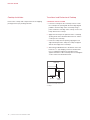
Important Note
To ensure this product is installed and operated as safely
and efciently as possible, take note of the following types
of highlighted information throughout this guide:
IMPORTANT NOTE highlights information that is especially
important.
CAUTION indicates a situation where minor injury or product
damage may occur if instructions are not followed.
WARNING states a hazard that may cause serious injury or
death if precautions are not followed.
IMPORTANT NOTE: Throughout this guide, dimensions in
parentheses are millimeters unless otherwise specied.
IMPORTANT NOTE: Save these instructions for the local
electrical inspector.

wolfappliance.com | 3
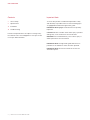
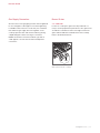
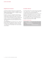
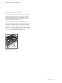
Product Information
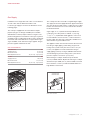
Important product information, including the model and
serial number, are listed on the product rating plate. The
rating plate is located on the bottom of the cooktop. Refer
to the illustration below.
If service is necessary, contact Wolf Factory Certied
Service with the model and serial number. For the name of
the nearest Wolf Factory Certied Service or for questions
regarding the installation, visit the Support & Service
section of our website, wolfappliance.com, or call Wolf
Customer Care at 800-222-7820.
Rating plate location
RATING PLATE
GAS COOKTOP

4 | Wolf Customer Care 800.222.7820
Installation Requirements
A minimum 2" (51) is required from the bottom of the
cooktop to combustible materials. If the cooktop is installed
above an oven, a minimum of
1
/4" (6) is required between the
units.
The Contemporary gas cooktop can be mounted ush
with the top of the countertop or as a standard installation
sitting on top of the countertop surface. If the cooktop is
to be mounted ush with the countertop, a recessed area
surrounding the cooktop cutout must be provided. The
countertop must be able to withstand temperatures up to
300°F
(149°C).
IMPORTANT NOTE: For ush installations, do not use the
cooktop as a template to create the countertop opening.
Use the countertop cutout template or specications pro-
vided. Failure to do so may cause damage.
SPECIFICATIONS
Electrical Requirements
Installation must comply with all applicable electrical codes.
Locate the electrical supply as shown in the illustrations
on the following pages. A separate circuit servicing only
this appliance is required. A ground fault circuit interrupter
(GFCI) is not recommended and may cause interruption of
operation.
ELECTRICAL REQUIREMENTS
Electrical Supply grounded, 120 VAC, 60 Hz
Service 15 amp dedicated circuit
Receptacle 3-prong grounding-type
Power Cord 6'
(1.8 m)

wolfappliance.com | 5
SPECIFICATIONS
Gas Supply
Installation must comply with local codes or, in the absence
of local codes, with the National Fuel Gas Code.
Locate the gas supply as shown in the illustrations on the
following pages.
The cooktop is equipped for use with natural or liquid
propane (LP) gas. It is design certied by the Canadian
Standards Association (CSA) for natural or LP gases. The
product rating plate has information on the type of gas that
should be used. For rating plate location, refer to the illustra-
tion below. If this information does not agree with the type
of gas available, check with the local gas supplier. The gas
pressure regulator is built into the unit.
GAS REQUIREMENTS
NATURAL GAS WC
Supply Pressure 5" (12.5 mb)
Min Line Pressure 7" (17.5 mb)
Max Regulator Pressure 14" (34.9 mb), .5 psi (3.5 kPa)
LP GAS WC
Supply Pressure 10" (25 mb)
Min Line Pressure 11" (27.4 mb)
Max Regulator Pressure 14" (34.9 mb), .5 psi (3.5 kPa)
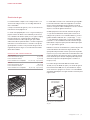
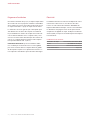
The cooktop must be connected to a regulated gas supply.
The supply line must be equipped with an approved external
gas shut-off valve located near the cooktop in an accessible
location. Do not block access to the shut-off valve. Refer to
the illustration below.
A gas supply of
3
/4" (19) ID line must be provided to the
cooktop. If local codes permit, a certied, 3'
(.9 m) long,
1
/2" (13) or
3
/4" (19) ID exible metal appliance connector is
recommended to connect the units
1
/2" NPT male inlet to
the gas supply line. Pipe joint compounds, suitable for use
with natural or LP gas should be used.
The appliance and its shut-off valve must be disconnected
from the gas supply piping system during any pressure
testing of the system at test pressures in excess of .5 psi
(3.5 kPa)
. The appliance must be isolated from the gas
supply piping system by closing its individual manual shut-
off valve during any pressure testing of the system at test
pressures equal to or less than .5 psi
(3.5 kPa).
Wolf natural gas cooktops will function up to 10,250'
(3124 m)
in altitude without adjustment and LP gas cooktops
will function up to 8,600'
(2621 m). If the installation exceeds
these elevations, contact your authorized Wolf dealer for a
high altitude conversion kit.
SHUT-OFF VALVE
OPEN POSITION
GAS SUPPLYTO APPLIANCE
Gas shut-off valve
Rating plate location
RATING PLATE

6 | Wolf Customer Care 800.222.7820
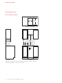
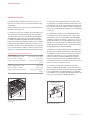
SPECIFICATIONS
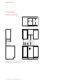
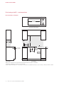
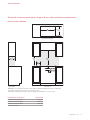
FRONT VIEW
SIDE
VIEW
COUNTERTOP CUTOUT
NO
TE: Shaded area above countertop indicates minimum clearance to combustible surfaces,
combus
tible materials cannot be located within this area.
13"
(330)
18"
(457)
7"
(178)
E G
30"
(762)
14"
(356)
19
1
/2"
(495)
2
1
/2" (64)
2
1
/2" (64)
15" Gas Cooktop
STANDARD INSTALLATION

wolfappliance.com | 7
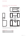
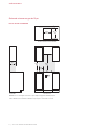
SPECIFICATIONS
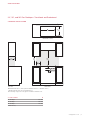
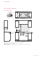
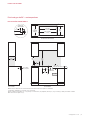
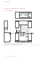
24", 30", and 36" Gas Cooktops—Transitional and Professional
STANDARD INSTALLATION
10"
(254)
4" (102)
3
1
/2" (89)
FRONT VIEW
SIDE
VIEW
COUNTERTOP CUTOUT
NO
TE: Shaded area above countertop indicates minimum clearance to combustible surfaces,
combus
tible materials cannot be located within this area.
El
ectrical and gas supply location only applies to installations with built-in oven.
30"
(762)
W
WIDTH
13"
(330)
18"
(457)
9"
(229)
19
1
/
2
"
(495)
2
1
/2" (64)
2
1
/
2
"
(64)
E G
CUTOUT WIDTH
W
24" Cooktop* 23" (584)
30" Cooktop 29" (737)
36" Cooktop 35" (889)
*Transitional only.

8 | Wolf Customer Care 800.222.7820
SPECIFICATIONS
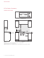
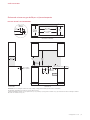
36" Gas Cooktop—Contemporary
STANDARD INSTALLATION
FRONT VIEW
SIDE
VIEW
NOTE:
Shaded area above countertop indicates minimum clearance to combustible surfaces,
combus
tible materials cannot be located within this area.
Ma
ximum facade thickness 1" (25). 1" (25) thickness extends 17" (432) left and right and 2" (51) above and below centerlines.
30"
(762)
13"
(330)
18"
(457)
9"
(229)
E G
35" (889)
CUTOUT WIDTH
COUNTERTOP CUTOUT
20"
(508)
2
1
/2" (64)
5"
(127)
C
L
10"
(254)
1
1
/4" (32)
DIAMETER
4" (102)
C
L
3
7
/
8
"
(98) MIN
–5
1
/
8
"
(130) MAX
2" (51) MIN–
5"
(127) MAX

wolfappliance.com | 9
SPECIFICATIONS
36" Gas Cooktop—Contemporary
FLUSH INSTALLATION
FRONT VIEW
SIDE
VIEW
NOTE:
Shaded area above countertop indicates minimum clearance to combustible surfaces,
combus
tible materials cannot be located within this area.
Ma
ximum facade thickness 1" (25). 1" (25) thickness extends 17" (432) left and right and 2" (51) above and below centerlines.
Outsid
e corner radius
3
/8" (10).
30"
(762)
13"
(330)
18"
(457)
9"
(229)
E G
36" (914) MIN
RECESS
21"
(533) MIN
RECESS
35"
(889)
CUTOUT WIDTH
COUNTERTOP CUTOUT
20"
(508)
2
1
/
2
"
(64)
5
/64"
(
2
)
1
/2"
(13) MAX
COUNTERTOP
PROFILE
5"
(127)
C
L
10"
(254)
1
1
/4" (32)
DIAMETER
4"
(102)
C
L
3
7
/8" (98) MIN–5
1
/8" (130) MAX
2" (51) MIN–
5"
(127) MAX

10 | Wolf Customer Care 800.222.7820
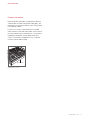
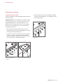
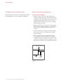
Transitional and Professional Cooktop
STANDARD INSTALLATION
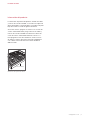
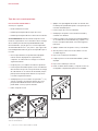
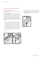
1 Lower the cooktop into the countertop cutout. Center
the cooktop in the opening with the front edge aligned
parallel to the front edge of the countertop. Using a
pencil, outline the rear edge of the cooktop on the coun-
tertop. Remove the cooktop.
2 Apply the foam strip to the perimeter of the countertop
opening. Refer to the illustration below. Do not seal the
cooktop to the countertop.
3 Insert the cooktop into the opening, aligning the rear
edge with the pencil line. Verify the cooktop is aligned
with the front edge of the countertop.
4 Attach the provided brackets to the bottom of the unit.
Insert the 3
1
/2" (89) clamping screws into the brackets.
Use a screwdriver to tighten the clamping screws
against the bottom of the countertop. Do not overtighten
screws. Refer to the illustration below.
Cooktop Installation
Remove the cooktop and components from the shipping
package and recycle packing materials.
INSTALLATION
FOAM STRIP
COUNTERTOP
BRACKET
CLAMPING
SCREW
Transitional and Professional
cooktop

wolfappliance.com | 11
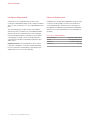
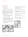
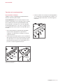
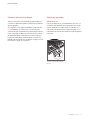
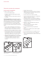
3 Install the bezels to the valve assemblies by rotating
clockwise until hand tight. Do not overtighten. Refer to
the illustration below.
Contemporary Cooktop
STANDARD INSTALLATION
An optional template has been provided to aid in placement
of the valve holes.
IMPORTANT NOTE: Prior to installing the cooktop, install the
valve stem spacers on the valve stem retainers to achieve
the appropriate depth. A 1"
(25) thick facade does not
require a spacer. For all facades less than 1"
(25), subtract
the thickness of the facade from 1"
(25) to determine the
required spacer thickness.
1 Once the proper spacing is determined, remove the
paper backing from the spacers and apply to each valve
stem. Refer to the illustration below.
2 Insert the front of the cooktop into the opening. Slightly
angle the cooktop to align each valve stem with the
holes in the façade. Then lower the back of the cooktop
into position. Refer to the illustration below.
INSTALLATION
SPACER
RETAINER
ALIGN
VALVE STEMS
Apply spacers prior to
installation
Insert Contemporary cooktop
BEZEL
Install bezels
wolfappliance.com
|
11

12 | Wolf Customer Care 800.222.7820
6 Apply a thin lm of petroleum jelly to the outermost
underside edge of the cooktop pan. The petroleum jelly
aids in future removal.
7 Insert the cooktop into the opening.
8 Ensure the cooktop is fully seated and centered in the
opening.
9 Install the bezels to the valve assemblies by rotating
clockwise until hand tight. Do not overtighten. Refer to
the illustration below.
10 Apply the sealant between the cooktop and countertop.
11 Use the squeegee to smooth the seam and remove
excess sealant.
12 Allow the sealant to set for 20 minutes.
13 Use denatured alcohol and paper towels to clean the
seam.
14 Allow 24 hours for the sealant to cure.
15 Use a stainless steel cleaner/polish to remove sealant
from the countertop and cooktop.
Contemporary Cooktop
FLUSH INSTALLATION
The following are provided:
• A required installation kit.
• An optional template to aid in cooktop placement.
• An optional template to aid in valve hole placement.
IMPORTANT NOTE: Prior to installing the cooktop, install the
valve stem spacers on the valve stem retainers to achieve
the appropriate depth. A 1"
(25) thick facade does not
require a spacer. For all facades less than 1"
(25), subtract
the thickness of the facade from 1"
(25) to determine the
required spacer thickness.
1 Once the proper spacing is determined, remove the
paper backing from the spacers and apply to each valve
stem. Refer to the illustration below.
2 Clean all surfaces of dust and debris.
3 Insert the front of the cooktop into the opening. Slightly
angle the cooktop to align each valve stem with the
holes in the façade and lower the back of the cooktop
into position. Refer to the illustration below.
4 Verify there is a gap of at least
1
/16" (2) to the countertop
around the perimeter of the cooktop. The gap allows
for heat expansion. The countertop may be damaged if
there is an insufcient gap.
5 Remove the cooktop.
INSTALLATION
SPACER
RETAINER
ALIGN
VALVE STEMS
Apply spacers prior to
installation
Insert Contemporary cooktop
BEZEL
Install bezels

wolfappliance.com | 13
Gas Supply Connection
All connections to the gas piping must be wrench-tightened.
Do not overtighten or allow pipes to turn when tightening.
If a exible metal connector is used, verify it is not kinked,
then attach the gas supply line to the regulator on the
cooktop. Open the valve and check for leaks by placing
a liquid detergent solution onto all gas connections.
Bubbles around the connections indicate a gas leak. If
a leak appears, close the shut-off valve and adjust the
connections.
INSTALLATION
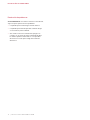
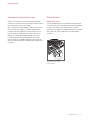
Burner Grates
24" COOKTOP
For the 24" cooktop, the grates must be positioned cor-
rectly to ensure proper burner performance. The grates have
an indicator on the bottom of the front edge. Position the
grates with the indicator toward the front of the cooktop.
Refer to the illustration below.
FRONT
Grate placement (24" cooktop)

14 | Wolf Customer Care 800.222.7820
Troubleshooting
IMPORTANT NOTE: If the cooktop does not operate
properly, follow these troubleshooting steps:
• Verify electrical power is supplied to the cooktop.
• Verify the gas supply shut-off valve is in the open
position.
• If the cooktop does not operate properly, contact Wolf
Factory Certied Service. Do not attempt to repair the
cooktop. Wolf is not responsible for service required to
correct a faulty installation.
TROUBLESHOOTING

wolfappliance.com | 15
Sub-Zero, Sub-Zero & Design, Sub-Zero & Snowake Design, Dual Refrigeration, The Living Kitchen, Great American Kitchens The Fine Art of Kitchen Design, Wolf, Wolf &
Design, Wolf Gourmet, W & Design, red colored knobs, Cove, and Cove & Design are registered trademarks and service marks of Sub-Zero Group, Inc. and its subsidiaries.
All other trademarks are property of their respective owners in the United States and other countries.

2 | Atención al cliente de Wolf 800.222.78200
ESTUFA DE GAS
Contenido
3 Estufa de gas
4 Especicaciones
10 Instalación
14 Resolución de problemas
Las características y especicaciones están sujetas a cam-
bios sin previo aviso. Visite wolfappliance.com/specs para
obtener la información más actualizada.
Aviso importante
Para garantizar que este producto se instale y opere de
la forma más segura y eciente posible, tome nota de los
siguientes tipos de información resaltada en esta guía:
AVISO IMPORTANTE señala la información que es especial-
mente importante.
PRECAUCIÓN indica una situación en la que se pueden
sufrir heridas leves o provocar daños al producto si no se
siguen las instrucciones.
ADVERTENCIA indica peligro de que se produzcan heridas
graves o incluso la muerte si no se siguen las precauciones.
AVISO IMPORTANTE: en toda esta guía, las dimensiones
entre paréntesis son milímetros, a menos que se especi-
que lo contrario.
AVISO IMPORTANTE: guarde estas instrucciones para el
inspector eléctrico local.

wolfappliance.com | 3
Información del producto
La información importante del producto, incluido el modelo
y número de serie de la unidad, se encuentra en la placa de
datos del producto. La placa de datos se localiza en la parte
baja de la estufa. Consulte la siguiente ilustración.
Si necesita servicio, póngase en contacto con el centro de
servicio autorizado de Wolf y tenga a la mano el modelo y
número de serie de la unidad. Para obtener los datos del
centro de servicio autorizado de Wolf más cercano o si
tiene preguntas acerca de la instalación, visite la sección
de Soporte y Servicio de nuestro sitio web, wolfappliance.
com o llame a la línea de atención al cliente de Wolf al
800-222-7820.
ESTUFA DE GAS
Ubicación de la placa de datos
PLACA DE DATOS

4 | Atención al cliente de Wolf 800.222.78200
Requisitos de instalación
Se requiere una distancia mínima de 2" (51) desde la parte
baja de la estufa hasta los materiales combustibles. Si se va
a instalar una estufa sobre un horno, se requiere un mínimo
de
1
/4" (6) entre las unidades.
El tope de cocina a gas contemporáneo puede montarse
al ras de la parte alta del mostrador o de manera estándar
asentada sobre la supercie del mostrador. Si el tope de
cocina va a montarse empotrado, al ras del mostrador, debe
contarse con un hueco en un área alrededor del tope de
cocina. El mostrador debe soportar temperaturas hasta de
149 °C
(300 °F).
AVISO IMPORTANTE: En las instalaciones al ras, no utilice el
tope de cocina como plantilla para señalar los oricios del
mostrador. Utilice la plantilla de recorte para el mostrador
o las especicaciones suministradas. De no hacerlo puede
ocasionar daños.
ESPECIFICACIONES
Instalación eléctrica
La instalación debe tener una conexión a tierra de conformidad
con los códigos locales o, en ausencia de códigos locales, con
el Código Nacional de Electricidad, ANSI/NFPA 70.
Coloque el suministro eléctrico tal y como se muestra en las
ilustraciones de las páginas 6–9. Es necesario un circuito
independiente, que dé servicio únicamente a este aparato.
No es recomendable utilizar un circuito de fallos de cone-
xión a tierra (GFCI, por sus siglas en inglés) ya que puede
interrumpir el funcionamiento de la unidad.
REQUISITOS ELÉCTRICOS
Suministro eléctrico Con conexión a tierra, 120 V CA, 60 Hz
Servicio Circuito dedicado de 15 amperes
Receptáculo Conexión a tierra de 3 clavijas
Cable de alimentación eléctrica 6'
(1.8 m)

wolfappliance.com | 5
ESPECIFICACIONES
Suministro de gas
La instalación debe cumplir con los códigos locales o, en
ausencia de códigos locales, con el Código Nacional de
Gas Combustible.
Coloque el suministro de gas tal y como se muestra en las
ilustraciones de las páginas 6–9.
La estufa está equipada para su uso con gas licuado (LP) o
propano natural. Su diseño está certicado por la Asocia-
ción Canadiense de Normas (CSA, por sus siglas en inglés)
para gas natural o LP. La placa de datos del producto
contiene información sobre el tipo de gas que se debe
utilizar. Para ubicar la placa de datos, consulte la siguiente
ilustración. Si esta información no coincide con el tipo de
gas disponible, consulte con el proveedor de gas local. El
regulador de presión de gas se encuentra interconstruido
dentro de la unidad.
REQUISITOS DEL SUMINISTRO DE GAS
GAS NATURAL WC
Presión del suministro de gas 5" (12.5 mb)
Presión mínima de la línea 7" (17.5 mb)
Presión máxima hacia el regulador 14" (34.9 mb), .5 psi (3.5 kPa)
GAS LP WC
Presión del suministro de gas 10" (25 mb)
Presión mínima de la línea 11" (27.4 mb)
Presión máxima hacia el regulador 14" (34.9 mb), .5 psi (3.5 kPa)
La estufa debe conectarse a un suministro de gas regulado.
La línea del suministro debe estar equipada con una llave
de paso externa aprobada para gas ubicada cerca de la
estufa en un lugar accesible. No bloquee el acceso a la llave
de paso. Consulte la siguiente ilustración.
Se debe proporcionar una línea de suministro de gas de
3
/4" (19) de línea de diámetro interno para la estufa. Si el
código local lo permite, se recomienda utilizar un conector
metálico exible certicado, de 3'
(.9 m) de largo,
1
/2" (13) o
3
/4" (19) de diámetro interior para conectar la entrada NPT
macho de
1
/2" de la unidad a la línea de suministro de gas.
Debe utilizar compuestos para juntas de tubería aptos para
uso con gas natural o gas LP.
Debe desconectar el electrodoméstico y la llave de paso del
sistema de tuberías del suministro de gas durante cual-
quier prueba de presión del sistema a presiones de prueba
mayores a 5 psi
(3.5 kPa). Debe aislar el electrodoméstico del
sistema de tuberías del suministro de gas cerrando manual-
mente la llave de paso durante cualquier prueba de presión
del sistema a presiones de prueba iguales o inferiores a
0.5psi
(3.5 kPa).
Las estufas de gas natural de Wolf funcionarán hasta
10,250'
(3124 m) de altitud sin ajuste y las estufas de gas LP
funcionarán hasta 8,600'
(2621 m). Si la instalación supera
estas elevaciones, póngase en contacto con su distribuidor
autorizado de Wolf para conseguir un kit de conversión para
regiones altas.
LLAVE DE PASO EN
POSICIÓN ABIERTA
SUMINISTRO
DE GAS
A LA UNIDAD
Llave de paso del suministro
de gas
Ubicación de la placa de datos
PLACA DE DATOS

6 | Atención al cliente de Wolf 800.222.78200
ESPECIFICACIONES
VISTA FRONTAL
VIST
A LATERAL
RECORTE DEL MOSTRADOR
NO
TA: la zona sombreada sobre el mostrador indica la distancia mínima a las superficies combustibles,
lo
s materiales combustibles no se pueden colocar en esta área.
13"
(330)
18"
(457)
7"
(178)
E G
30"
(762)
14"
(356)
19
1
/2"
(495)
2
1
/2" (64)
2
1
/2" (64)
Estufa de gas de 15"
INSTALACIÓN ESTÁNDAR
A página está carregando...
A página está carregando...
A página está carregando...
A página está carregando...
A página está carregando...
A página está carregando...
A página está carregando...
A página está carregando...
A página está carregando...
A página está carregando...
A página está carregando...
A página está carregando...
A página está carregando...
A página está carregando...
A página está carregando...
A página está carregando...
A página está carregando...
A página está carregando...
A página está carregando...
A página está carregando...
A página está carregando...
A página está carregando...
A página está carregando...
A página está carregando...
-
 1
1
-
 2
2
-
 3
3
-
 4
4
-
 5
5
-
 6
6
-
 7
7
-
 8
8
-
 9
9
-
 10
10
-
 11
11
-
 12
12
-
 13
13
-
 14
14
-
 15
15
-
 16
16
-
 17
17
-
 18
18
-
 19
19
-
 20
20
-
 21
21
-
 22
22
-
 23
23
-
 24
24
-
 25
25
-
 26
26
-
 27
27
-
 28
28
-
 29
29
-
 30
30
-
 31
31
-
 32
32
-
 33
33
-
 34
34
-
 35
35
-
 36
36
-
 37
37
-
 38
38
-
 39
39
-
 40
40
-
 41
41
-
 42
42
-
 43
43
-
 44
44


Sub-Zero CG365C/S Guia de instalação
- Tipo
- Guia de instalação
em outras línguas
- español: Sub-Zero CG365C/S Guía de instalación
- français: Sub-Zero CG365C/S Guide d'installation
- English: Sub-Zero CG365C/S Installation guide
Artigos relacionados
-
Sub-Zero CE152TF/S Guia de instalação
-
Wolf 24 inch E Series Guia de instalação
-
Sub-Zero CG243TF/S/LP Manual do proprietário
-
Sub-Zero Cooktop ICBCT15G Manual do usuário
-
Sub-Zero DO30PM/S/PH Guia de instalação
-
Wolf OG30 Guia de instalação
-
-
-
Outros documentos
-
Wolf CE152TF/S Guia de instalação
-
LG CBGJ3023S Instruções de operação
-
-
-
-
Wolf Appliance Company ICBIG15 Manual do usuário
-
Bosch NGM8654UC/03 Guia de instalação
-
-
-