
OUTDOOR GAS GRILL
INSTALLATION GUIDE
SPECIFICATIONS, INSTALLATION, AND MORE

OUTDOOR GAS GRILL
Contents
3 Outdoor Gas Grill
4 Safety Precautions
5 Specications
9 Installation
18 Troubleshooting
Features and specications are subject to change at any
time without notice. Visit wolfappliance.com/specs for the
most up-to-date information.
2
|
Wolf Customer Care 800.222.7820
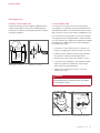
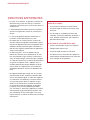
Important Note
To ensure this product is installed and operated as safely
and efciently as possible, take note of the following types
of highlighted information throughout this guide:
IMPORTANT NOTE highlights information that is especially
important.
CAUTION indicates a situation where minor injury or product
damage may occur if instructions are not followed.
WARNING states a hazard that may cause serious injury or
death if precautions are not followed.
IMPORTANT NOTE: Throughout this guide, dimensions in
parentheses are millimeters unless otherwise specied.
IMPORTANT NOTE: Save these instructions for the local
electrical inspector.

wolfappliance.com
|
3
OUTDOOR GAS GRILL
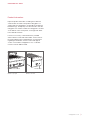
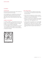
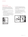
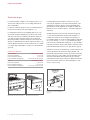
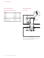
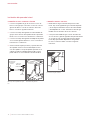
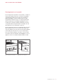
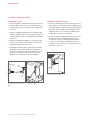
Product Information
Important product information, including the model and
serial number, are listed on the product rating plate. For
outdoor grills, the rating plate is located above the drip tray,
behind the logo. The drip tray must be removed to view the
rating plate. For outdoor modules, the rating plate is located
on the bottom of the control panel, on the right side. Refer
to the illustrations below.
If service is necessary, contact Wolf Factory Certied
Service with the model and serial number. For the name of
the nearest Wolf Factory Certied Service or for questions
regarding the installation, visit the contact and support
section of our website, wolfappliance.com, or call Wolf
Customer Care at 800-222-7820.
Outdoor gas grill
Outdoor module
RATING PLATE
RATING PLATE

4
|
Wolf Customer Care 800.222.7820
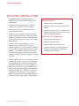
IMPORTANT INSTRUCTIONS
• Wolf outdoor gas grills and modules are for
outdoor use only. Do not install or operate in an
enclosed area.
• Installation must be performed by a qualied
installer, service agency or the gas supplier.
• Warranty service must be performed by Wolf
Factory Certied Service.
• Do not store or use gasoline or other ammable
liquids or vapors in the vicinity of this or any other
appliance. An LP gas cylinder not connected for
use shall not be stored in the vicinity of this or any
other appliance.
• In Massachusetts: All gas products must be
installed using a “Massachusetts” licensed
plumber or gastter. A “T” handle type manual gas
valve must be installed in the gas supply line to this
appliance. This applies to permanently installed
natural gas and propane installations. This does
not apply to propane portable installations using a
20-lb tank.
• A built-in appliance for use with a remote self-con-
tained LP gas supply system must use rigid pipe,
semi-rigid tubing, or a connector complying with
the Standard for Connectors for Gas Appliances,
ANSI Z21.24/CSA 6.10, or the Standard for Con-
nectors for Outdoor Gas Appliances and Manufac-
tured Homes, ANSI Z21.75/CSA 6.27, to connect
the appliance to the remote self-contained gas
supply system. When using semi-rigid tubing, alu-
minum, or aluminum alloy tubing is not permitted.
BEFORE LIGHTING:
• Read instructions before lighting.
• Open the hood or remove the cover before
lighting.
• If ignition does not occur in 5 seconds, turn
the burner control(s) off, wait 5 minutes, and
repeat the lighting procedure.
WHAT TO DO IF YOU SMELL GAS:
• Shut off gas to the appliance.
• Extinguish any open ames.
• Open the hood or remove the cover.
• If the odor continues, keep away from the
appliance and immediately call your gas
supplier or re department.
SAFETY PRECAUTIONS

wolfappliance.com
|
5
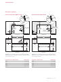
Installation Requirements
For portable applications, Wolf grill carts are designed
specically to t grill models OG30, OG36 and OG42 and
the side burner. Model OG54 is designed for built-in appli-
cations only.
For built-in applications, Wolf outdoor grills and the burner
module are designed for easy placement into a built-in
enclosure. For outdoor grills, installation in a combustible
enclosure requires an insulating liner. For the burner module,
an insulating liner is not required. The enclosure should be
built according to specications for your specic installa-
tion on the following pages. If the burner module is installed
next to an outdoor grill, a minimum of 12"
(305) is required
between the units on the rotisserie motor side and 2"
(51) on
the opposite side. A rotisserie side conversion kit is avail-
able from an authorized Wolf dealer.
Grill carts, insulating liners, and stainless steel doors and
drawers are avail able through an authorized Wolf dealer. For
local dealer information, visit the nd a showroom section of
our website, wolfappliance.com.
SPECIFICATIONS
Electrical Requirements
Installation must comply with all applicable electrical codes.
The electrical outlet must be located within reach of the
power cord. A separate circuit, servicing only this appliance
is required.
IMPORTANT NOTE: A ground fault circuit interrupter (GFCI)
is required to reduce the risk of electrical shock.
ELECTRICAL REQUIREMENTS
Electrical Supply grounded, 120 VAC, 60 Hz
Service 15 amp dedicated circuit
Receptacle 3-prong grounding-type, GFCI
Power Cord 6'
(1.8 m), 9' (2.7 m) rotisserie

6
|
Wolf Customer Care 800.222.7820
SPECIFICATIONS
Gas Supply
Installation must comply with local codes or, in the absence
of local codes, with the National Fuel Gas Code.
Locate the gas supply within the shaded area shown in the
illustrations on pages 7–8.
The outdoor grill is equipped for use with natural or liquid
propane (LP) gas. It is design certied by the Canadian
Standards Association (CSA) for natural or LP gases. The
product rating plate has information on the type of gas that
should be used. For rating plate location, refer to the illustra-
tion below. If this information does not agree with the type
of gas available, check with the local gas supplier.
GAS REQUIREMENTS
NATURAL GAS WC
Supply Pressure 5" (12.5 mb)
Min Line Pressure 7" (17.5 mb)
Max Regulator Pressure 14" (34.9 mb), .5 psi (3.5 kPa)
LP GAS WC
Supply Pressure 10" (25 mb)
Min Line Pressure 11" (27.4 mb)
Max Regulator Pressure 14" (34.9 mb), .5 psi (3.5 kPa)
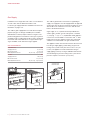
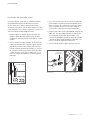
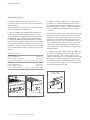
The outdoor grill must be connected to a regulated gas
supply. The supply line must be equipped with an approved
external gas shut-off valve located near the grill in an acces-
sible location. Do not block access to the shut-off valve.
Refer to the illustration below.
A gas supply of
3
/4" (19) ID line must be provided to the
outdoor grill or module. If local codes permit, a certied,
3'
(.9 m) long,
1
/2" (13) or
3
/4" (19) ID exible metal appliance
connector is recommended to connect the units
1
/2" NPT
female inlet to the gas supply line. Pipe joint compounds,
suitable for use with natural or LP gas should be used.
The appliance and its shut-off valve must be disconnected
from the gas supply piping system during any pressure
testing of the system at test pressures in excess of .5 psi
(3.5 kPa)
. The appliance must be isolated from the gas
supply piping system by closing its individual manual shut-
off valve during any pressure testing of the system at test
pressures equal to or less than .5 psi
(3.5 kPa).
Outdoor gas grill
Outdoor module
RATING PLATE
RATING PLATE
SHUT-OFF VALVE
OPEN POSITION
GAS SUPPLYTO APPLIANCE
Gas shut-off valve

wolfappliance.com
|
7
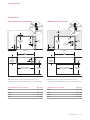
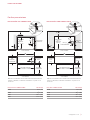
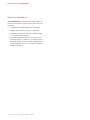
SPECIFICATIONS
11
3
/4"
(298)
OPENING
HEIGHT
DOORS / DRAWERS
OPENING WIDTH
24
1
/4" (616)
OPENING
DEPTH
OPENING
HEIGHT
6"
(152)
1" (25) min
GRILL
OPENING
13
/
16
"
(21)
COUNTERTOP
OVERHANG
GRILL
OVERLAP
FRONT VIEW
TOP VIEW
W
OPENING WIDTH
NO
TE: Shaded area above countertop indicates minimum clearance to
combus
tible surfaces, combustible materials cannot be located within this area.
2
1
/2" (64)
13"
(330)
3
1
/2"
(89)
G
4"
(102)
6"
(152)
G
12
5
/8"
(321)
OPENING
HEIGHT
DOORS / DRAWERS
OPENING WIDTH
26" (660)
OPENING
DEPTH
OPENING
HEIGHT
12"
(305)
1" (25) min
10
3
/
4
"
(273)
5"
(127)
C
L
C
L
2
3
/4" (70)
KNOCKOUT
LINER
OPENING
13
/
16
"
(21)
COUNTERTOP
OVERHANG
LINER
OVERLAP
FRONT VIEW
TOP VIEW
W
OPENING WIDTH
NOTE: Shaded area above countertop indicates minimum clearance to
combustible surfaces, combustible materials cannot be located within this area.
12"
(305)
G
NON-COMBUSTIBLE ENCLOSURE
WIDTH (W)
OG30 28
1
/2" (724)
OG36 34
1
/2" (876)
OG42 40
1
/2" (1029)
OG54 52
1
/2" (1334)
Outdoor Grills
NON-COMBUSTIBLE INSTALLATION COMBUSTIBLE INSTALLATION
COMBUSTIBLE ENCLOSURE
WIDTH (W)
OG30 33
1
/2" (851)
OG36 39
1
/2" (1003)
OG42 45
1
/2" (1156)
OG54 57
1
/2" (1461)

8
|
Wolf Customer Care 800.222.7820
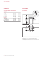
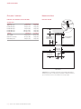
SPECIFICATIONS
10" (254)
OPENING
HEIGHT
24
1
/4" (616)
OPENING
DEPTH
6"
(152)
MODULE
OPENING
9
/16"
(14)
COUNTERTOP
OVERHANG
MODULE
OVERLAP
FRONT VIEW
TOP VIEW
12"
(305)
OPENING
NOTE: Shaded area above countertop indicates minimum clearance to
combustible surfaces, combustible materials cannot be located within this area.
An insulating liner is not required.
G
8"
(203)
7"
(178)
G
3"
(76)
12" (305)
Burner Module
INSTALLATION
Outdoor Grills
ACCESSORY DOORS AND DRAWERS
OPENING
DOORS W H
18" Single 16
1
/4" (413) 19" (483)
30" Double 28
1
/4" (718) 19" (483)
36" Double 34
1
/4" (870) 19" (483)
42" Double 40
1
/4" (1022) 19" (483)
54" Double 52
1
/4" (1327) 19" (483)
DRAWERS W H
Single Drawer 27
1
/4" (692) 9
3
/4" (248)
2- or 3-Drawer Unit 12
1
/8" (308) 19" (483)
Drawer | Door Unit 29
1
/4" (743) 19" (483)

wolfappliance.com
|
9
INSTALLATION
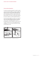
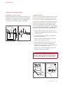
Gas Supply Line
NATURAL GAS CONNECTION
Install the natural gas pressure regulator supplied with the
outdoor product with the arrow on the regulator pointing
towards the unit. Refer to the illustrations below for a typical
natural gas installation.
REGULATOR
REAR GAS
CONNECTION
BOTTOM GAS
CONNECTION
SHUT-OFF
VALVE
FROM GAS
SUPPLY
REGULATOR
TO GRILL
ADAPTER
CLOSE
NIPPLE
VENT
Natural gas connection
Natural gas regulator
LP GAS CONNECTION
For a whole house LP gas connection, the LP gas pres-
sure regulator is not provided. It can be purchased from an
authorized Wolf dealer. For local dealer information, visit the
nd a showroom section of our website, wolfappliance.com.
For connection to LP gas cylinder, use only the LP gas pres-
sure regulator and hose supplied with the outdoor product.
Use only a 20-lb LP gas cylinder with an approved overlling
preventive device (OPD) and shut-off valve terminating in
the cylinder valve outlet.
1 Connect the
3
/8" are end of the hose to the unit cou-
pling. Do not apply pipe sealant to the are connection.
2 Install the LP gas cylinder, pull out the shelf, and place
the cylinder on it. Refer to the illustration below.
3 Ensure the gas valve on top of the cylinder is closed.
4 Connect the LP gas regulator to the cylinder and hand-
tighten only. Open the cylinder valve. Check for gas
leaks. Refer to the illustration below.
5 Tighten the LP tank retention screw to secure the
cylinder to the shelf.
WARNING
Perform a gas leak test each time the LP gas cylinder is
changed. Do not place more than one LP gas cylinder
in an enclosure at a time.
LP TANK
RETENTION SCREW
GRILL
COUPLING
COUPLING
NUT
REGULATOR
VENT
TO GRILL
LP tank shelf
LP gas cylinder connection

10
|
Wolf Customer Care 800.222.7820
INSTALLATION
Gas Supply Line
LP GAS SAFETY REQUIREMENT
This gas appliance and its individual shut-off valve must
be disconnected from the gas supply piping system during
any pressure testing of that system at test pressures greater
than .5 psi (3.5 kPa).
This gas appliance must be isolated from the gas supply
piping system by closing its individual manual shut-off valve
during pressure testing of the gas supply piping system at
test pressures equal to or less than .5 psi (3.5 kPa).
GAS LEAK TESTING
Perform a gas leak test at least once a year, each time the
LP gas cylinder is connected to the regulator, and any time
part of the gas line is disconnected or replaced. This applies
to natural gas as well as LP gas.
1 Prepare a leak testing solution of half liquid soap and
half water in a spray bottle.
2 Verify all control knobs are in the OFF position.
3 Turn the cylinder valve knob counterclockwise one turn
to open.
4 Spray the leak testing solution on pipe joints, ttings,
and hose. Bubbles in the solution indicate a gas leak.
5 Tighten any loose joint or replace any faulty part with a
Wolf replacement part to stop the leak. Do not attempt to
repair the cylinder valve. If damaged, the cylinder must
be replaced.
6 If the leak persists, shut off the gas supply at the cylinder
valve and remove the LP gas cylinder. Call Wolf Factory
Certied Service. Do not use the outdoor product until
the leak has been xed.
7 Push in and turn any control knob to the ON position to
release pressure, then turn the control knob back to OFF.
WARNING
To prevent re or explosion hazard, do not smoke or
permit sources of ignition in the area while performing
a gas leak test. Perform the gas leak test outdoors in a
well ventilated area. Never use an open ame to check
for gas leaks.

wolfappliance.com
|
11
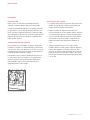
Installation
PREPARATION
Remove and recycle packing materials. Remove labels and
the protective plastic lm from the grill.
Place the briquette trays in the grill above the burners with
the ash tubes positioned at the front. Refer to the illus-
tration below. Place the burner grates directly above the
briquette trays with the square openings in the grates at the
front.
POWER TRANSFORMER
For a built-in installation, secure the transformer box in a dry
location, away from the grill rebox and excessive heat area,
but within 2'
(.6 m) of the right rear opening. Do not install
the transformer box inside the insulating liner.
For a cart installation, mount the transformer box by the two
screws located at the bottom right rear corner of the grill
cart, behind the pull-out shelf. Use the same transformer for
the side burner if installed.
FLASH TUBE
Flash tube position
CART INSTALLATION
1 Two mounting screws are provided at the bottom right
rear corner of the cart for the power transformer. Install
the transformer box.
2 Remove the front mounting screws from the cart. Place
the grill onto the cart, allowing enough space at the back
to make the connection to the transformer.
3 Make the connections from the wiring harness located at
the right rear of the grill to the transformer, then slide the
grill back until it is fully engaged with the cart.
4 Secure the grill to the cart with the four screws provided.
Mounting holes in the upper back corners of the grill will
align with the holes in the cart. Secure with two screws.
Remove the drip tray. Install two screws through the side
mounting holes below the grill front panel and into the
cart.
INSTALLATION

12
|
Wolf Customer Care 800.222.7820
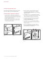
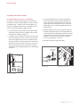
Side Burner Installation
The Wolf side burner can be installed on the right side of
any Wolf grill cart.
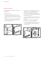
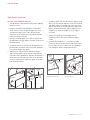
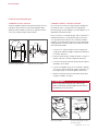
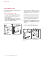
PREPARE GRILL CART
1 If installed, the right side shelf must be removed. To
remove, lift the shelf up so the lower front screw is
exposed, then remove the screw. Refer to the illustration
below.
2 Fold the side shelf down and remove the upper front
screw, then remove the side shelf and front bracket.
Refer to the illustration below.
LOWER SCREW
UPPER
SCREW
SIDE SHELF
FRONT
BRACKET
Side shelf lower screw
Side shelf upper screw
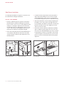
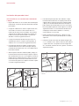
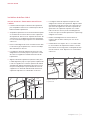
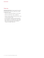
3 Remove the rear screws and bracket, then remove the
cart plug from the access hole by pushing out from
inside the cart. Refer to the illustration below.
4 For easier access, the upper rear panel and right side
door of the cart can be removed. Remove the rear panel
by removing the four screws.
5 To remove the right side door, depress the rear lever on
each hinge, then remove the door. Refer to the illustra-
tion below.
6 For easier access, the drip tray of the grill can be
removed. To remove, slide forward and lift out.
7 Insert the provided plastic bushing through the access
hole from inside the grill cart where the cart plug was
removed previously.
REAR
BRACKET
CART PLUG
REAR LEVER
DRIP TRAY
Remove rear bracket and plug
Remove cart door
INSTALLATION

wolfappliance.com
|
13
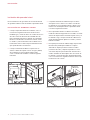
Side Burner Installation
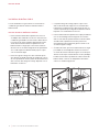
INSTALL SIDE BURNER SHROUD
1 The side burner is placed inside the shroud for shipping.
Lift out to remove.
2 Hang the shroud by hand-starting the four provided
10-32 machine screws through the upper slots of the
shroud into the upper holes of the cart. Do not fully
tighten the screws until the shroud is properly aligned.
Refer to the illustration below.
3 Place the provided alignment tool with the lip placed in
the gap between the grill and the shroud as shown in the
illustration below.
4 To align the front of the shroud, push the alignment tool
back until the center block of the tool is ush against the
front vertical ange of the shroud.
5 Align the front of the shroud (up and down) with the
alignment tool until the top of the tool is ush with the
top surface of the grill bullnose. Align the shroud (front to
back) with the tool until the front of the tool is ush with
the front of the bullnose. Tighten the upper screw. Refer
to the illustration below.
SCREWS
SCREWS
ALIGNMENT
TOOL
SURFACES
FLUSH
UPPER
SCREW
Hang shroud
Align front of shroud
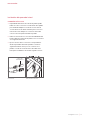
6 To align the back of the shroud, place the alignment tool
at the rear of the shroud. Align the rear of the shroud (up
and down) with the tool until the top of the tool is ush
with the top surface of the grill. Tighten the upper screw.
Refer to the illustration below. With the alignment tool,
verify the front of the shroud did not move, realign if
necessary.
7 Remove the alignment tool and tighten the two
remaining screws to the slots just below the upper
screws.
8 Install the two provided
5
/16 x
3
/8 hex drive shoulder
screws into the lower holes of the shroud and through
the cart. Place the two
1
/4–20 hex nuts from inside the
cart and tighten. Refer to the illustration below.
ALIGNMENT
TOOL
SURFACES
FLUSH
UPPER
SCREW
SHOULDER
SCREWS
HEX NUT
(INSIDE CART)
Align back of shroud
Secure shroud
INSTALLATION

14
|
Wolf Customer Care 800.222.7820
Side Burner Installation
For natural gas installations, the gas line connection must
be made before installing the side burner.
INSTALL SIDE BURNER
1 Place the side burner into the shroud as shown in the
illustration below. Guide the exible gas line and wire
harness into the cart access hole. Verify alignment of the
unit prior to securing the side burner to the shroud. If
the side burner does not align properly, remove, loosen
screws, and check the shroud alignment with the tool.
Reposition the side burner until properly aligned.
2 Place a bar clamp with protected ends behind bullnose
on the re box and under the shroud. Do not include
any part of bullnose within the bar clamp. Refer to the
illustration below.
3 Compress the bar clamp until the hole in the bullnose
aligns with the threaded hole in the shroud. The align-
ment and placement of this screw is very important to
the side burner alignment. Refer to the illustration below.
4 Attach the side burner to the shroud by rst placing the
provided 8-32 hex cap screw into the right side of the
front underside of the bullnose and into the shroud. Then
place the left side hex cap screw. Tighten the screws
and remove the bar clamp.
5 At the rear of the unit, push the side burner toward the
grill to establish the proper gap at the rear. Loosen the
rear cart screws and shift the grill if necessary to achieve
the proper gap. Install the two provided 8-18 pan head
screws through the shroud and into the rear of the side
burner as shown in the illustration below. Verify proper
alignment.
INSTALLATION
ACCESS HOLE
Position side burner
Position bar clamp
HOLES
ALIGN
REAR
SCREWS
Hole alignment
Secure side burner

wolfappliance.com
|
15
Side Burner Installation
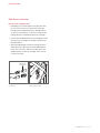
ELECTRICAL CONNECTION
1 Depending on the serial number of the grill, there may
be one or two connectors near the front of the grill
just above the manifold. Refer to the auxiliary harness
section for serial numbers. Locate the connector(s) by
looking above the manifold near the front of the grill.
2 Remove the unpopulated connector housing(s) from the
wire harness(es) coming from the grill as shown in the
illustration below.
3 Attach the appropriate connector housing(s) from the
side burner to the grill. Refer to the illustration below.
If only one connector is found on the grill, refer to the
auxiliary harness section for assembly of the second
connector housing.
INSTALLATION
UNPOPULATED
CONNECTORS
UNPOPULATED
CONNECTORS
AUXILLARY
HARNESS
Connectors
Connector housing

16
|
Wolf Customer Care 800.222.7820
Side Burner Installation
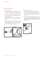
LP GAS CONNECTION
1 Connect the 2-stage LP gas regulator to the are tee at
the location shown. Connect the are swivel connector
to one end of the are tee. Refer to the illustration below.
2 Connect the regulator assembly to the exible gas line
coming into the grill cart from the side burner as shown
in the illustration below.
3 Connect the regulator assembly to the grill manifold at
the are swivel connector as shown in the illustration
below.
4 Reinstall the rear panel and door of the grill cart. Reposi-
tion the grill drip tray. Place the burner cap on the burner
head, place the grate on the burner pan, and afx the
knob to the bezel with the bezel nylon liner.
NATURAL GAS CONNECTION
1 Split the high pressure natural gas line into two lines,
one to attach to the grill natural gas regulator and one
to attach to the side burner via the exible line and
1
/2"
NPT adapter. Place the exible gas line through the cart
access hole.
2 Place the exible gas line through the cart access hole
and attach to the side burner regulator at the pipe elbow.
The elbow may be rotated to face downward for larger
adapters. Do not rotate the elbow upward. Refer to the
illustration below.
INSTALLATION
FLARE
SWIVEL
LP GAS
REGULATOR
FLARE
TEE
FLEXIBLE
GAS LINE
GRILL
MANIFOLD
LP gas regulator assembly
LP gas connection
Natural gas connection

wolfappliance.com
|
17
Side Burner Installation
AUXILIARY HARNESS (IF APPLICABLE)
If the Wolf outdoor grill has a serial number prior to the
numbers listed (OG30: 11364339, OG36: 11363946,
OG42: 11363911), an auxiliary harness will be provided
with the side burner. If not, contact Wolf Customer Care at
800-222-7820.
1 The upper rear panel of the grill cart must be removed
to install the auxiliary harness. Remove the rear panel by
removing the four screws.
2 With the provided wire ties, attach the auxiliary harness
to the re box n or existing wire harness. The 4-pin
connector cluster should be placed facing the rear of grill
and the 2-pin connector facing the front. The harness
must be tied down tightly and must not touch the grill re
box. Refer to the illustration below.
3 If connected, disconnect the transformer 4-pin con-
nector at the rear of the grill. Attach one of the 4-pin
connectors to the 4-pin connector attached to the grill.
Attach the other 4-pin connector to the 4-pin connector
from the transformer.
4 Remove the unpopulated connector housing from the
wire harness coming from the grill. Insert each con-
nector housing from the side burner harness to the
corresponding housing on the grill harness and on the
auxiliary harness. There are two connections to be made.
Refer to the illustrations below.
5 Reinstall the upper rear panel of the cart.
INSTALLATION
Auxiliary harness
UNPOPULATED
CONNECTORS
UNPOPULATED
CONNECTORS
AUXILLARY
HARNESS
Connectors
Connector housing

18
|
Wolf Customer Care 800.222.7820
TROUBLESHOOTING
Troubleshooting
IMPORTANT NOTE: If the outdoor gas grill does not operate
properly, follow these troubleshooting steps:
• Verify electrical power is supplied to the grill.
• Verify proper gas supply.
• Verify the gas supply shut-off valve is in the open
position.
• If the outdoor gas grill does not operate properly, contact
Wolf Factory Certied Service. Do not attempt to repair
the grill. Wolf is not responsible for service required to
correct a faulty installation.

Sub-Zero, Sub-Zero & Design, Sub-Zero & Snowake Design, Dual Refrigeration, The Living Kitchen, Great American Kitchens The Fine Art of Kitchen Design, Wolf, Wolf &
Design, Wolf Gourmet, W & Design, red colored knobs, Cove, and Cove & Design are registered trademarks and service marks of Sub-Zero Group, Inc. and its subsidiaries.
All other trademarks are property of their respective owners in the United States and other countries.

2
|
Atención al cliente de Wolf 800.222.7820
PARRILLA DE GAS PARA EXTERIORES
Contenido
3 Parrilla de gas para exteriores
4 Precauciones de seguridad
5 Especicaciones
9 Instalación
18 Resolución de problemas
Las características y especicaciones están sujetas a cam-
bios sin previo aviso. Visite wolfappliance.com/specs para
obtener la información más actualizada.
Aviso importante
Para garantizar que este producto se instale y opere de
la forma más segura y eciente posible, tome nota de los
siguientes tipos de información resaltada en esta guía:
AVISO IMPORTANTE señala la información que es especial-
mente importante.
PRECAUCIÓN indica una situación en la que se pueden
sufrir heridas leves o provocar daños al producto si no se
siguen las instrucciones.
ADVERTENCIA indica peligro de que se produzcan heridas
graves o incluso la muerte si no se siguen las precauciones.
AVISO IMPORTANTE: En toda esta guía, las dimensiones
entre paréntesis son milímetros, a menos que se especique
lo contrario.
AVISO IMPORTANTE: Guarde estas instrucciones para el
inspector eléctrico local.
A página está carregando ...
A página está carregando ...
A página está carregando ...
A página está carregando ...
A página está carregando ...
A página está carregando ...
A página está carregando ...
A página está carregando ...
A página está carregando ...
A página está carregando ...
A página está carregando ...
A página está carregando ...
A página está carregando ...
A página está carregando ...
A página está carregando ...
A página está carregando ...
A página está carregando ...
A página está carregando ...
A página está carregando ...
A página está carregando ...
A página está carregando ...
A página está carregando ...
A página está carregando ...
A página está carregando ...
A página está carregando ...
A página está carregando ...
A página está carregando ...
A página está carregando ...
A página está carregando ...
A página está carregando ...
A página está carregando ...
A página está carregando ...
A página está carregando ...
A página está carregando ...
A página está carregando ...
A página está carregando ...
-
 1
1
-
 2
2
-
 3
3
-
 4
4
-
 5
5
-
 6
6
-
 7
7
-
 8
8
-
 9
9
-
 10
10
-
 11
11
-
 12
12
-
 13
13
-
 14
14
-
 15
15
-
 16
16
-
 17
17
-
 18
18
-
 19
19
-
 20
20
-
 21
21
-
 22
22
-
 23
23
-
 24
24
-
 25
25
-
 26
26
-
 27
27
-
 28
28
-
 29
29
-
 30
30
-
 31
31
-
 32
32
-
 33
33
-
 34
34
-
 35
35
-
 36
36
-
 37
37
-
 38
38
-
 39
39
-
 40
40
-
 41
41
-
 42
42
-
 43
43
-
 44
44
-
 45
45
-
 46
46
-
 47
47
-
 48
48
-
 49
49
-
 50
50
-
 51
51
-
 52
52
-
 53
53
-
 54
54
-
 55
55
-
 56
56


Wolf OG30 Guia de instalação
- Categoria
- Churrascos
- Tipo
- Guia de instalação
em outros idiomas
- español: Wolf OG30 Guía de instalación
- français: Wolf OG30 Guide d'installation
- English: Wolf OG30 Installation guide
Artigos relacionados
-
Wolf Appliance Company ICBIG15 Manual do usuário
-
Wolf 24 inch E Series Guia de instalação
-
-
Sub-Zero CG243TF/S/LP Manual do proprietário
-
Wolf CE152TF/S Guia de instalação
-
Sub-Zero CE152TF/S Guia de instalação
-
-
Sub-Zero GR484CG Guia de usuario
Outros documentos
-
 ClosetMaid 1237 Guia de instalação
-
Sub-Zero CW24/B Guia de usuario
-
LG CBGJ3023S Instruções de operação
-
-
-
Sub-Zero OG30 Guia de usuario
-
Sub-Zero DO30PM/S/PH Guia de instalação
-
Sub-Zero PWC482418 Guia de instalação
-
Sub-Zero CG365C/S Guia de instalação
-
Desa CHAM55N Manual do proprietário
