
PRO WALL CHIMNEY HOOD
INSTALLATION GUIDE
SPECIFICATIONS, INSTALLATION, AND MORE

2 | Wolf Customer Care 800.222.7820
PRO WALL CHIMNEY HOOD
Contents
3 Pro Wall Chimney Hood
4 Specications
6 Installation
10 Blower Specications
11 Troubleshooting
Features and specications are subject to change at any
time without notice. Visit wolfappliance.com/specs for the
most up-to-date information.
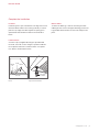
Important Note
To ensure this product is installed and operated as safely
and efciently as possible, take note of the following types
of highlighted information throughout this guide:
IMPORTANT NOTE highlights information that is especially
important.
CAUTION indicates a situation where minor injury or product
damage may occur if instructions are not followed.
WARNING states a hazard that may cause serious injury or
death if precautions are not followed.
IMPORTANT NOTE: Throughout this guide, dimensions in
parentheses are millimeters unless otherwise specied.
IMPORTANT NOTE: Save these instructions for the local
electrical inspector.

wolfappliance.com | 3
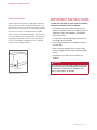
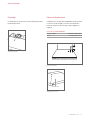
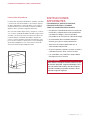
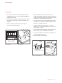
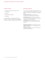
Product Information
Important product information, including the model and
serial number, are listed on the product rating plate. The
rating plate is located on an inside wall of the hood shell
(lters need to be removed). Refer to the illustration below.
If service is necessary, contact Wolf Factory Certied
Service with the model and serial number. For the name of
the nearest Wolf Factory Certied Service or for questions
regarding the installation, visit the contact and support
section of our website, wolfappliance.com, or call Wolf
Customer Care at 800-222-7820.
PRO WALL CHIMNEY HOOD
Rating plate location
RATING PLATE
IMPORTANT INSTRUCTIONS
TO REDUCE THE RISK OF FIRE, ELECTRIC SHOCK,
OR INJURY, OBSERVE THE FOLLOWING:
• Installation work and electrical wiring must be
done by qualied person(s) in accordance with all
applicable codes and standards, including re-
rated construction.
• Two installers are recommended due to the size
and weight of the pro hood.
• Install the pro hood only with a blower manufac-
tured by Wolf.
• When cutting or drilling into the wall or ceiling,
do not damage electrical wiring and other hidden
utilities.
• Ducted fans must always be vented to the
outdoors.
CAUTION
To reduce the risk of re and properly exhaust air,
be certain to duct air outside. Do not vent exhaust
air into spaces within walls or ceilings or into
attics, crawl spaces, or garages.

4 | Wolf Customer Care 800.222.7820
SPECIFICATIONS
Installation Requirements
Install the hood 30" (762) to 36" (914) from the bottom of the
hood to the countertop.
BLOWER ASSEMBLIES
Pro Wall Chimney Hoods require an internal, in-line, or
remote blower assembly, avail able through an authorized
Wolf dealer. For local dealer information, visit the nd a
showroom section of our website, wolfappliance.com.
Refer to specic installation instructions provided with each
blower assembly.
DUCT COVER
Optional stainless steel duct covers, in multiple heights, are
available through your authorized Wolf dealer. Duct covers
must be attached to the hood prior to hood installation. For
local dealer information, visit the nd a showroom section of
our website, wolfappliance.com.
Ducting
WARNING
To reduce the risk of re, use only metal ducting.
IMPORTANT NOTE: Consult a qualied HVAC professional
for specic installation and ducting applications.
Pro Wall Chimney Hoods accommodate a 10"
(254) round
duct. Use only rigid metal ducting.
A straight, short duct run allows the hood to perform most
efciently. If the duct run exceeds 50'
(15 m), a higher CFM
blower may be required to maintain proper air ow.
Internal and in-line blowers require a roof or wall cap.
Connect ducting to the cap or to the remote blower and
work back towards the hood. Use sheet metal screws and
high-temperature duct tape to seal joints between ducting
sections.
Pro Wall Chimney Hoods include a backdraft damper. Local
codes may require the use of an additional backdraft and/or
make-up air damper. Contact your local HVAC professional
for specic requirements.
A make-up air damper is available through an authorized
Wolf dealer. For local dealer information, visit the nd a
showroom section of our website, wolfappliance.com.

wolfappliance.com | 5
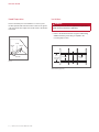
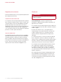
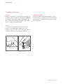
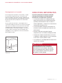
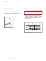
Discharge
Pro Wall Chimney Hoods have a vertical discharge. Refer to
the illustration below.
SPECIFICATIONS
2" (51)
Vertical discharge
Electrical Requirements
Installation must comply with all applicable electrical codes.
Locate the electrical supply as shown in the illustration
below. A separate circuit servicing only this appliance is
required.
ELECTRICAL REQUIREMENTS
Electrical Supply grounded, 120 VAC, 60 Hz
Service 15 amp dedicated circuit
E
6"
(152)
5"
(127)
30" (762) TO 36" (914) BOTTOM EDGE TO COUNTERTOP
Electrical location
Rating plate location
RATING PLATE

6 | Wolf Customer Care 800.222.7820
INSTALLATION
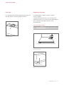
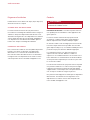
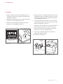
Installation
WARNING
Wall framing must be able to support the weight of the
hood and internal blower, if applicable.
1 Refer to the illustration below for typical wall framing.
Additional framing or blocking is required in the
mounting strip location.
C
L
BLOCKING
MOUNTING
STRIP
18"
(457)
TO BOTTOM
OF HOOD
Wall framing (typical)
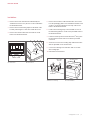
Hood Preparation
Remove the lters prior to installation. To remove, press
the lter upward and rotate the bottom. Remove the grease
cups from the bottom edge of the hood. Refer to the illustra-
tion below.
SIDE VIEW
SPRING
FILTER
GREASE
CUP
Filters

wolfappliance.com | 7
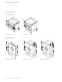
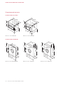
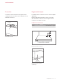
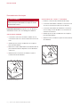
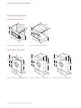
5 Remove the transition, hold-down brackets, and screws
from the packaging and use the hold-down brackets and
screws to secure the transition to the top of the hood.
Refer to the illustration below.
6 Position the mounting strip on the wall and secure it to
the wall framing with the wood screws provided. Refer to
the illustration below.
7 Lift the hood into position and insert Romex
®
wire(s) into
the electrical knockout and secure with the provided
connector.
8 Secure the hood to the mounting strip and wall structure
with the provided screws and washers.
9 Connect the ducting to the transition and secure with
duct sealing tape.
10 Reinstall the internal frame.
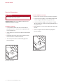
Installation
2 Remove the hood’s internal frame indicated by the
shaded area. Remove only the four screws indicated in
the illustration below.
3 Remove the wood mounting strip from the back of the
hood by extracting the screws from inside the hood.
4 Remove the electrical box from the inside the hood.
Refer to the illustration below.
INSTALLATION
HOLD-DOWN
BRACKET
TRANSITION
MOUNTING STRIP
16
3
/4"
(426)
Transition mounting
Hood installation
REMOVE SCREWS
ELECTRICAL
BOX
Internal frame
Electrical box

8 | Wolf Customer Care 800.222.7820
INSTALLATION
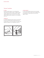
Electrical Connections
WARNING
Before making electrical connections, verify the power
is turned off at the service panel.
IMPORTANT NOTE: Refer to installation instructions pro-
vided with the blower assembly.
INTERNAL BLOWER
1 Connect black to black and white to white with the
provided connectors, and connect the green/bare wire
to the ground screw.
2 Verify all wires are secure and not pinched, and reinstall
the box.
3 Plug the blower power cord into the receptacle inside
the hood. Refer to the illustration below.
4 Turn on the power to the hood and verify light and
blower operation.
IN-LINE/REMOTE BLOWER
1 Remove the connector from the end of the orange wire.
2 Connect the home supply. Connect black to black and
connect the green/bare wire to the ground screw.
3 Connect the blower supply. Connect black to orange,
all three white wires, and connect the green/bare wire to
the ground screw.
4 Verify all wires are secure and not pinched, and reinstall
the box.
5 Turn on the power to the hood and verify light and
blower operation.
RECEPTACLE
ELECTRICAL
BOX
Electrical connections
ELECTRICAL
BOX
Electrical connections

wolfappliance.com | 9
INSTALLATION
Complete the Installation
FILTERS
Install the grease cups at the bottom rear edge of the hood.
Orient the lters with the lines running vertically. To install,
place the top edge of the lter against the spring, press
upward and rotate the bottom. Refer to the illustration
below.
LIGHT BULBS
A suction-cup-style light bulb changer is provided with
the hood. To install, use the changer to push the bulb into
the receptacle and rotate counterclockwise one-quarter
turn. Refer to the illustration below.
WOLF LOGO
To attach the Wolf logo, clean the mounting area with
rubbing alcohol. Remove the paper backing, position the
logo parallel with the bottom of the hood, and press into
place.
SIDE VIEW
SPRING
FILTER
GREASE
CUP
LIGHT BULB
CHANGER
Filters
Light bulb installation

10 | Wolf Customer Care 800.222.7820
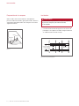
BLOWER SPECIFICATIONS
Blower Dimensions
IN-LINE BLOWERS
24
1
/2
"
(622)
15
1
/2
"
(394)
28
1
/4
"
(718)
20
3
/4
"
(527)
24
3
/4
"
(629)
14"
(356)
4
3
/4
"
(121)
10" (254)
DIAMETER
14
3
/4
"
(375)
29
1
/2
"
(749)
29
1
/2
"
(749)
18" (457)
22"
(559)
10
1
/8
"
(257)
7
1
/4
"
(184)
10"
(254)
10" (254)
DIAMETER
14
3
/4
"
(375)
29
1
/2
"
(749)
29
1
/2
"
(749)
21" (533)
25"
(635)
10
3
/8
"
(264)
7
1
/4
"
(184)
10"
(254)
10" (254)
DIAMETER
600/900 CFM remote blower
1200 CFM remote blower
1500 CFM remote blower
18"
(457)
22"
(559)
24
7
/8
"
(632)
12"
(305)
18"
(457)
8"
(203)
1100 CFM in-line blower
11
3
/4"
(298)
21
1
/2"
(546)
24
3
/8"
(619)
18
1
/2"
(470)
12
1
/4"
(311)
4
1
/2"
(114)
600 CFM in-line blower
REMOTE BLOWERS

wolfappliance.com | 11
Troubleshooting
IMPORTANT NOTE: If the hood does not operate properly,
follow these troubleshooting steps:
• Verify electrical power is supplied to the hood.
• Verify proper wiring connections.
• If the hood does not operate properly, contact Wolf
Factory Certied Service. Do not attempt to repair the
hood. Wolf is not responsible for service required to
correct a faulty installation.
TROUBLESHOOTING
Sub-Zero, Sub-Zero & Design, Sub-Zero & Snowake Design, Dual Refrigeration, The Living Kitchen, Great American Kitchens The Fine Art of Kitchen Design, Wolf, Wolf &
Design, Wolf Gourmet, W & Design, red colored knobs, Cove, and Cove & Design are registered trademarks and service marks of Sub-Zero Group, Inc. and its subsidiaries.
All other trademarks are property of their respective owners in the United States and other countries.

2 | Atención al cliente de Wolf 800.222.7820
CAMPANA CHIMENEA DE PARED PROFESIONAL
Contenido
3 Campana chimenea de pared profesional
4 Especicaciones
6 Instalación
10 Especicaciones del extractor
11 Solución de problemas
Las características y especicaciones están sujetas a
cambios sin previo aviso. Visite wolfappliance.com/specs
para obtener la información más actualizada.
Aviso importante
Para garantizar que este producto se instale y opere de
la forma más segura y eciente posible, tome nota de los
siguientes tipos de información resaltada en este manual:
AVISO IMPORTANTE señala la información que es
especialmente importante.
PRECAUCIÓN indica una situación en la que se pueden
sufrir heridas leves o provocar daños al producto si no se
siguen las instrucciones.
ADVERTENCIA indica peligro de que se produzcan heridas
graves o incluso la muerte si no se siguen las precauciones.
AVISO IMPORTANTE: En toda esta guía, las dimensiones
entre paréntesis son milímetros, a menos que se especique
lo contrario.
AVISO IMPORTANTE: guarde estas instrucciones para el
inspector eléctrico local.

wolfappliance.com | 3
Información del producto
La información importante del producto, incluidos el modelo
y el número de serie de la unidad, se encuentra en la placa
de datos del producto. La placa de datos se encuentra en
una pared interior de la carcasa de la campana (se deben
quitar los ltros). Consulte la siguiente ilustración.
Si es necesario realizar algún servicio, póngase en contacto
con el servicio certicado de fábrica de Wolf y tenga a mano
el modelo y el número de serie. Para obtener los datos del
Centro de Servicio Certicado de la fábrica de Wolf más
cercano o si tiene preguntas acerca de la instalación, visite
la sección de contacto y soporte técnico en nuestra página
de Internet wolfappliance.com; o bien, llame a la línea de
atención al cliente de Wolf al 800-222-7820.
CAMPANA CHIMENEA DE PARED PROFESIONAL
Ubicación de la placa de datos
PLACA DE DATOS
INSTRUCCIONES
IMPORTANTES
PARA REDUCIR EL RIESGO DE INCENDIO,
DESCARGA ELÉCTRICA O LESIONES,
TOME LAS SIGUIENTES PRECAUCIONES:
• Una persona calicada debe realizar el trabajo de
instalación y cableado eléctrico de conformidad
con todos los códigos y normas aplicables,
incluyendo los de construcción a prueba de fuego.
• Se recomiendan dos instaladores debido al
tamaño y peso de la campana profesional.
• Solo instale la campana profesional con un
extractor fabricado por Wolf.
• Al cortar o perforar la pared o el techo, no dañe el
cableado eléctrico ni otros servicios ocultos.
• Los ventiladores con conductos siempre deben
descargarse hacia el exterior.
PRECAUCIÓN
Para reducir el riesgo de incendio y extraer el aire
de manera apropiada, asegúrese de dirigir el aire
hacia el exterior. No ventile el aire del escape en
espacios cerrados por paredes o techos, áticos,
espacios angostos o garajes.

4 | Atención al cliente de Wolf 800.222.7820
ESPECIFICACIONES
Requisitos de instalación
Instale la cubierta 30" (762) a 36" (914) desde la parte inferior
de la campana a la encimera.
CONJUNTOS DE EXTRACTOR
Las campanas chimenea de pared profesionales requieren
que se instale un extractor interno, en línea o remoto, que
se puede obtener a través de un distribuidor autorizado
de Wolf. Para obtener más información acerca de los
distribuidores locales, visite la sección para encontrar una
sala de exposición de nuestro sitio web, wolfappliance.
com. Consulte las instrucciones de instalación especícas
provistas con cada conjunto de extractor.
TAPA DE CONDUCTO
Hay disponibles tapas de conducto de acero inoxidables
opcionales de diversas alturas a través de un distribuidor
autorizado de Wolf. Las tapas de conducto se pueden
jar a la campana antes de la instalación de esta última.
Para obtener más información acerca de los distribuidores
locales, visite la sección para encontrar una sala de
exposición de nuestro sitio web, wolfappliance.com.
Conductos
ADVERTENCIA
Para reducir el riesgo de incendio, utilice solamente
conductos metálicos.
AVISO IMPORTANTE: Consulte a un profesional de
climatización calicado para la instalación especíca y las
aplicaciones de conductos.
Las campanas chimenea de pared profesionales admiten un
conducto redondo de 10"
(254). Utilice solamente conductos
metálicos rígidos.
Un tramo de conductos recto y corto permite que la
campana tenga un mejor funcionamiento. Si el tramo de
conducto supera las 50'
(15 m), se puede necesitar un
extractor CFM más alto para mantener un ujo de aire
adecuado.
Los extractores internos y en línea necesitan una rejilla de
techo o de pared. Conecte los conductos a la rejilla o al
extractor remoto y trabaje hacia la campana. Utilice tornillos
de metal y cinta para conductos de alta temperatura para
sellar las uniones entre las secciones de los conductos.
Las campanas chimenea de pared profesionales incluyen
una compuerta de contraujo de aire. Es posible que
los códigos locales exijan que se utilice una compuerta
adicional de contraujo o aire renovable. Comuníquese
con un profesional local de climatización para conocer los
requisitos especícos.
Una compuerta de aire renovable está disponible a través
de un distribuidor autorizado de Wolf. Para obtener más
información acerca de los distribuidores locales, visite la
sección para encontrar una sala de exposición de nuestro
sitio web, wolfappliance.com.

wolfappliance.com | 5
Descarga
Las campanas chimenea de pared profesionales tienen una
descarga vertical. Consulte la siguiente ilustración.
ESPECIFICACIONES
2" (51)
Descarga vertical
Requisitos eléctricos
La instalación debe cumplir con todos los códigos
eléctricos vigentes.
Coloque el suministro eléctrico como se muestra en la
siguiente ilustración. Se necesita un circuito independiente
que le suministre electricidad únicamente a este
electrodoméstico.
REQUISITOS ELÉCTRICOS
Suministro eléctrico Con conexión a tierra, 120 V CA, 60 Hz
Servicio Circuito dedicado de 15 amperes
E
6"
(152)
5"
(127)
30" (762) A 36" (914) DESDE EL BORDE INFERIOR A LA ENCIMERA
Ubicación eléctrica
Ubicación de la placa de datos
PLACA DE DATOS

6 | Atención al cliente de Wolf 800.222.7820
INSTALACIÓN
Instalación
ADVERTENCIA
La estructura de la pared debe ser capaz de soportar
el peso de la campana y del extractor interno,
si corresponde.
1 Consulte la ilustración de abajo para ver los marcos de
pared típicos. Se requiere encuadre o bloqueo adicional
en el Ubicación de la tira de montaje.
C
L
ENTRAMADO
BANDA DE
MONTAJE
16
3
/4"
(426)
DESDE LA PARTE
INFERIOR DE
LA CAMPANA
Estructura de pared (típica).
Preparación de la campana
Quite los ltros antes de la instalación. Para quitarlos,
presione el ltro hacia arriba y gire la parte inferior. Retire los
engrasadores del borde inferior de la campana. Consulte la
siguiente ilustración.
VISTA LATERAL
RESORTE
FILTRO
ENGRASADOR
Filtros

wolfappliance.com | 7
5 Retire la transición, los soportes de sujeción y los
tornillos, del embalaje y utilizar los soportes de sujeción y
tornillos para asegurar la transición a la parte superior de
la campana. Consulte la siguiente ilustración.
6 Coloque la tira de montaje en la pared y fíjela a el marco
de la pared con los tornillos de madera proporcionados.
Referirse a la siguiente ilustración.
7 Levante la cubierta hasta su posición e inserte los
cables Romex
®
en el knockout eléctrico y seguro con el
proporcionado conector.
8 Fije la cubierta a la tira de montaje y la estructura de la
pared con los tornillos y arandelas suministrados.
9 Conecte los conductos a la transición y asegúrelos con
cinta de sellado de conductos.
10 Vuelva a instalar el marco interno.
INSTALACIÓN
Instalación
2 Retire el marco interno del capó indicado por el Area
sombreada. Quite solo los cuatro tornillos indicados en
la siguiente ilustración.
3 Retire la tira de montaje de madera de la parte posterior
del campana extrayendo los tornillos del interior de la
campana.
4 Retire la caja eléctrica del interior de la campana.
Consulte la siguiente ilustración.
SOPORTE
SUJECIÓN
TRANSICIÓN
BANDA DE MONTAJE
16
3
/4"
(426)
Montaje de la transición
Instalación de la campana
QUITAR TORNILLOS
CAJA
ELÉCTRICA
Marco interno
Caja electrica

8 | Atención al cliente de Wolf 800.222.7820
INSTALACIÓN
Conexiones eléctricas
ADVERTENCIA
Antes de realizar las conexiones eléctricas, verique
que la corriente eléctrica esté apagada en el panel
de servicio.
AVISO IMPORTANTE: Consulte las instrucciones de
instalación provistas con el conjunto de extractor.
EXTRACTOR INTERNO
1 Conecte de negro a blanco y de blanco a blanco con el
conectores provistos, y conecte el cable verde/desnudo
al tornillo de tierra.
2 Verique que todos los cables estén seguros y no estén
pellizcados, y reinstálelos la caja.
3 Enchufe el cable de alimentación del soplador en el
receptáculo interior la capucha. Consulte la siguiente
ilustración.
4 Encienda la campana y verique la luz y funcionamiento
del soplador.
EXTRACTOR EN LÍNEA / REMOTO
1 Retire el conector del extremo del cable naranja.
2 Conecte la fuente de la casa. Conecte negro con negro y
conecte el cable verde/pelado al tornillo de tierra.
3 Conecte el suministro de soplador. Conecte negro con
naranja, los tres cables blancos, y conecte el cable
verde/desnudo a el tornillo de tierra.
4 Verique que todos los cables estén seguros y no
pellizcados, y vuelva a instalarlos la caja.
5 Encienda la campana y verique la luz y funcionamiento
del soplador.
CAJA
ELÉCTRICA
Conexiones eléctricas
RECEPTÁCULO
CAJA
ELÉCTRICA
Conexiones eléctricas

wolfappliance.com | 9
INSTALACIÓN
Complete la instalación
FILTROS
Instale los engrasadores en los bordes traseros inferiores de
la campana. Oriente los ltros con las tuberías instaladas de
forma vertical. Para instalar, coloque el borde superior del
ltro contra el resorte, presione hacia arriba y gire la parte
inferior. Consulte la siguiente ilustración.
FOCOS
Se suministra un cambiador de foco tipo ventosa. Para
instalar, use el cambiador para empujar el foco en el
receptáculo y gire en sentido contrario a las agujas del reloj
un cuarto de vuelta. Consulte la siguiente ilustración.
LOGOTIPO DE WOLF
Para jar el logotipo de Wolf, limpie el lugar de montaje
con alcohol. Retire el papel protector, coloque el logotipo
de forma paralela a la parte inferior de la campana, luego
presione para jarlo.
VISTA LATERAL
RESORTE
FILTRO
ENGRASADOR
CAMBIADOR
DE FOCO
Filtros
Instalación de focos

10 | Atención al cliente de Wolf 800.222.7820
ESPECIFICACIONES DEL EXTRACTOR
Dimensiones del extractor
EXTRACTORES EN LÍNEA
24
1
/2
"
(622)
15
1
/2
"
(394)
28
1
/4
"
(718)
20
3
/4
"
(527)
24
3
/4
"
(629)
14"
(356)
4
3
/4
"
(121)
10" (254)
DE DIÁMETRO
14
3
/4
"
(375)
29
1
/2
"
(749)
29
1
/2
"
(749)
18" (457)
22"
(559)
10
1
/8
"
(257)
7
1
/4
"
(184)
10"
(254)
10" (254)
DE DIÁMETRO
14
3
/4
"
(375)
29
1
/2
"
(749)
29
1
/2
"
(749)
21" (533)
25"
(635)
10
3
/8
"
(264)
7
1
/4
"
(184)
10"
(254)
10" (254)
DE DIÁMETRO
Extractor remoto 600/900 CFM
Extractor remoto 1200 CFM
Extractor remoto 1500 CFM
18"
(457)
22"
(559)
24
7
/8
"
(632)
12"
(305)
18"
(457)
8"
(203)
Extractor en línea 1100 CFM
11
3
/4"
(298)
21
1
/2"
(546)
24
3
/8"
(619)
18
1
/2"
(470)
12
1
/4"
(311)
4
1
/2"
(114)
Extractor en línea 600 CFM
EXTRACTORES REMOTOS
A página está carregando...
A página está carregando...
A página está carregando...
A página está carregando...
A página está carregando...
A página está carregando...
A página está carregando...
A página está carregando...
A página está carregando...
A página está carregando...
A página está carregando...
A página está carregando...
-
 1
1
-
 2
2
-
 3
3
-
 4
4
-
 5
5
-
 6
6
-
 7
7
-
 8
8
-
 9
9
-
 10
10
-
 11
11
-
 12
12
-
 13
13
-
 14
14
-
 15
15
-
 16
16
-
 17
17
-
 18
18
-
 19
19
-
 20
20
-
 21
21
-
 22
22
-
 23
23
-
 24
24
-
 25
25
-
 26
26
-
 27
27
-
 28
28
-
 29
29
-
 30
30
-
 31
31
-
 32
32


Sub-Zero PWC362418 Guia de instalação
- Categoria
- Exaustores
- Tipo
- Guia de instalação
em outras línguas
- español: Sub-Zero PWC362418 Guía de instalación
- français: Sub-Zero PWC362418 Guide d'installation
- italiano: Sub-Zero PWC362418 Guida d'installazione
- English: Sub-Zero PWC362418 Installation guide
Artigos relacionados
Outros documentos
-
Wolf 5610509 Guia de instalação
-
-
Thermador PH60GS Guia de instalação
-
Thermador VCIN54GWS Guia de instalação
-
Wolf CE152TF/S Guia de instalação
-
-
JennAir 5005520415 585 or 1170 CFM Internal Blower For Range Hoods Manual do usuário
-
-
Dwyer Series SAH Manual do usuário