Thermador PH60GS Guia de instalação
- Categoria
- Exaustores
- Tipo
- Guia de instalação
Este manual também é adequado para

THERMADOR PROFESSIONAL SERIES
®
60'' Wall Hoods

Table of Contents (English)................................................................ 2
Table de Matières (Français) ........................................................... 21
Índice de Materias (Español)........................................................... 41
THERMADOR PROFESSIONAL SERIES
®
60'' Wall Hoods
Hottes Murales de la Série 60'' PROFESSIONAL
MC
de THERMADOR
Para Campanas de Pared 60'' PROFESSIONAL
®
de THERMADOR
Models | Modèles | Modelos
PH60GS

Table of Contents English | 2 |
Table of Contents
This THERMADOR
®
appliance is made by
BSH Home Appliances Corporation
1901 Main Street, Suite 600
Irvine, CA 92614
Questions?
1-800-735-4328
www.thermador.com
We look forward to hearing from you!
Safety ............................................................................................................................................................................... 3
Advanced Planning ......................................................................................................................................................... 5
Before You Begin........................................................................................................................................................ 5
General Information .................................................................................................................................................... 6
Installation Preparation................................................................................................................................................... 7
Installation Considerations ......................................................................................................................................... 7
Electrical Requirements .............................................................................................................................................. 7
Ductwork Preparation ................................................................................................................................................ 8
Choosing the Correct Blower ...................................................................................................................................... 10
Hood Transition........................................................................................................................................................... 10
Installation Instructions.................................................................................................................................................. 12
Wall Mount Installation................................................................................................................................................ 12
Cabinet Installation ..................................................................................................................................................... 14
Wire Routing ............................................................................................................................................................... 16
Blower Motor Installation............................................................................................................................................. 16
Grease Trays, Filters and Spacers ............................................................................................................................. 20
Heat Lamp Installation ................................................................................................................................................ 20
Customer Support, Accessories & Parts ........................................................................................................ back page
Safety Definitions
NOTICE: This indicates that damage to the appliance or property may occur as a result of non-compliance with this
advisory.
Note: This alerts you to important information and/or tips.
WARNING
This indicates that death or serious injuries may occur as
a result of non-observance of this warning.
CAUTION
This indicates that minor or moderate injuries may occur
as a result of non-observance of this warning.

Installation Instructions English | 3 |
Safety
IMPORTANT SAFETY INSTRUCTIONS
READ AND SAVE THESE INSTRUCTIONS
INSTALLER: Please leave these Instructions with this unit
for the owner. Save these Instructions for the Local
Inspector’s use.
OWNER: Please retain these instructions for future
reference.
Safety Codes and Standards
This appliance complies with the following Standards:
• UL 507, Standard for the Safety of Electrical Fans
• CAN/CSA-C22.2 No. 113, Fans and Ventilators
It is the responsibility of the owner and installer to
determine if additional requirements and/or standards
apply to specific installations. Always refer to local codes to
ensure all requirements are met.
If required by the National Electrical Code (or Canadian
Electrical Code), this appliance must be installed on a
separate branch circuit.
INSTALLER — show the owner the location of the circuit
breaker. Mark it for easy reference.
Never modify or alter the construction of the appliance. For
example, do not remove panels or wire covers.
Examine the appliance after unpacking it. In the event of
transport damage, DO NOT plug it in.
WARNING
If the information in this manual is not followed exactly, fire
or shock may result causing property damage or personal
injury.
DO NOT repair or replace any part of the appliance
unless specifically recommended in the manuals.
Improper installation, service or maintenance can cause
injury or property damage or void product warranty. Refer
to this manual for guidance. All other servicing should be
done by an authorized servicer.
CAUTION
The unit is heavy and should be handled
accordingly. Proper safety equipment such as
gloves and adequate manpower of at least two
people must be used in moving the hood to
avoid injury and to avoid damage to the unit or
the floor.
Rings, watches, and any other loose items that may
damage the unit or otherwise might become entangled
with the unit should be removed.
Hidden surfaces may have sharp edges. Use caution
when reaching behind or under appliance.
WARNING
Repairs should only be done by a trained servicer.
Improper repair of your appliance may result in risk of
severe physical injury or death.
WARNING
When properly cared for, your new appliance has been
designed to be safe and reliable. Read all instructions
carefully before use. These precautions will reduce the
risk of burns, electric shock, fire, and injury to persons.
When using kitchen appliances, basic safety precautions
must be followed, including these in the following pages.
WARNING
Turn off power circuit at service panel and lock out panel
before wiring this appliance. Requirement: 120 VAC, 60
Hz 20 A. Allow the appliance to cool after the power has
been turned off before servicing the appliance.
WARNING
To reduce the risk of fire use only metal ductwork.
CAUTION
Vent unit to the outside of building only. This unit is only
designed to be vented outside. It should not be used for
recirculation mode.

Installation Instructions English | 4 |
IMPORTANT SAFETY INSTRUCTIONS
READ AND SAVE THESE INSTRUCTIONS
Grounding Instructions
This appliance must be grounded. In the event of an
electrical short circuit, grounding reduces the risk of electric
shock by providing an escape wire for the electric current.
Be sure your appliance is properly installed and grounded
by a qualified technician. Installation, electrical connections
and grounding must comply with all applicable codes.
WARNING – TO REDUCE THE RISK OF FIRE,
ELECTRIC SHOCK AND INJURY TO PERSONS
OBSERVE THE FOLLOWING:
• This ventilator assembly must be installed with
THERMADOR
®
recommended blowers only. Contact
Customer Service for additional options.
• Use this unit only in the manner intended by the
manufacturer. If you have questions, contact Customer
Service at 1-800-735-4328.
• Before servicing or cleaning unit, switch power OFF at
the service panel. Lock the service panel to prevent
power from being turned ON accidentally. When the
service panel cannot be locked, securely fasten a
prominent warning device, such as a tag, to the service
panel.
• Installation work and electrical wiring must be done by
qualified person(s) in accordance with all applicable
codes and standards, including fire-rated construction.
• Sufficient air is needed for proper combustion and
exhausting of gases through the flue (chimney) of fuel
burning equipment to prevent back drafting. Follow the
heating equipment manufacturer’s guideline and safety
standards such as those published by the National Fire
Protection Association (NFPA), and the American
Society for Heating, Refrigeration and Air Conditioning
Engineers (ASHRAE), and the local code authorities.
• When cutting or drilling into wall or ceiling, do not
damage electrical wiring and other hidden utilities.
• Ducted fans must always be vented to the outdoors.
• To properly exhaust air, be sure to duct air outside. Do
not vent exhaust air into spaces within walls, ceilings,
attics, crawl spaces or garages.
WARNING
Improper grounding can result in a risk of electric shock.
Consult a qualified electrician if the grounding instructions
are not completely understood, or if doubt exists as to
whether the appliance is properly grounded.
WARNING
To Reduce The Risk Of Fire Or Electric Shock
DO NOT use this fan with any solid-state speed control
devices.
WARNING
Local building codes may require the use of make-up air
systems when using ducted ventilation systems greater
than specified CFM of air movement. The specified CFM
varies from locale to locale. Consult your HVAC
professional for specific requirements in your area.
CAUTION
For general ventilating use only. DO NOT use to exhaust
hazardous or explosive materials or vapors.
WARNING
State of California Proposition 65 Warnings:
This product contains chemicals known to the State of
California to cause cancer, birth defects or other
reproductive harm.
WARNING
Halogen lights might be hot. Disconnect from
power and allow to cool before servicing.

Installation Instructions English | 5 |
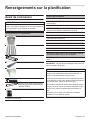
Advanced Planning
Before You Begin
IMPORTANT: DO NOT throw away any packaging until
appliance is fully installed.
CAUTION
Before installing, turn power OFF at the service panel.
Lock service panel to prevent power from being turned
ON accidentally.
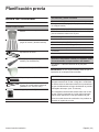
Parts Included
Metal transition with backdraft damper
Stainless steel baffle filters
Filter spacers
Grease trays
175W Heat lamps
Remote blower adapter
Wooden bracket used as Hood
Mounting Bracket (part of install- DO
NOT THROW AWAY)
Fastener assortment
Literature packet
Tools and Parts Needed
Aluminum tape (DO NOT use duct tape)
1/2'' (13 mm) Conduit if required (follow local codes)
1'' (25.4 mm) Strain relief
EXTNCB25 – 25 ft. Blower Connector Cable for distances
up to 25 ft.
Ducting as needed
Blower
Flat head and Phillips screwdrivers
Drill with 3/16'' (4.76 mm) drill bit
3/8'' (9.52 mm) nut driver or socket and ratchet
Wire stripper
Protective work gloves
Optional accessories available for separate purchase.
Refer to www.thermador.com for more details.
EXTNCB25 – 25 ft. Blower Connection Cable
WARNING
To avoid risk of burn, turn the hood ON when cooking at
high heat or when flambéing food.
DO NOT use all heating elements or gas burners
simultaneously at high settings for a prolonged period.
(max.15 minutes).
If the hood is located over a gas cooktop, operate the
hood at maximum setting whenever three or more gas
burners are being used.
DO NOT operate the ventilation system during a cooktop
fire.

Installation Instructions English | 6 |
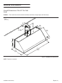
General Information
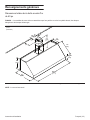
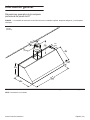
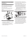
Overall Dimensions of the 60'' Pro Wall
Hood
PH60GS — This model series features brushed stainless-steel filters, halogen lights, and heat lamps.
NOTE: Transition is centered.
Figure 1: PH60GS Overall Dimensions
6"
(152)
7½"
7½"
7½"
(190)
(190)
12"
(305)
12"
(305)
12"
(305)
12"
(305)
12"
(305)
12"
(305)
18"
(457)
18"
(457)
18"
(457)
27"
(686)
27"
(686)
27"
(686)
4
4
3
3
/
/16
16
16
"
"
(106)
(106)
(106)
59
59
59
15
15
15
/
/16
16
16
"
"
(1523)
(1523)
dia. 10"
(254)
dia. 10"
(254)
dia. 10"
(254)
inches
(millimeters)

Installation Instructions English | 7 |
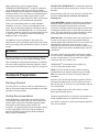
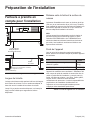
Installation Preparation
Installation Considerations
Hood Width
The hood width should be no less than the width of the
cooking surface. For proper performance, the housing must
cover the entire cooking surface.
For proper performance, the hood must be centered
horizontally above the cooking surface.
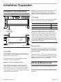
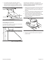
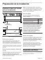
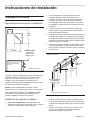
Distance From Cooking Surface
Hood installation height above a cooktop, rangetop or
range can vary. The installation height ranges from a
minimum height of 30'' (762 mm) to a maximum height of
40'' (1,016 mm); however, it is necessary to follow the
cooking appliance manufacturer’s installation instructions
for proper hood height (Figure 2).
NOTICE: The hood could incur some damage from heat if
a THERMADOR PROFESSIONAL
®
series range or
rangetop is operated with multiple burners at high settings
under a hood that is installed at minimum clearances.
Unit Weight
When calculating the load for the housing support system,
be sure to consider the weight of the ventilation unit.
Blower Motors
Integral, in-line and remote blowers are available through
your authorized THERMADOR
®
dealer. For local dealer
information, visit the Find a Dealer section of our website at
www.thermador.com.
The blower will vary in size and is dictated by the cooking
surface, the volume of air that needs to be moved and the
length of the duct run. Refer to the Ventilation Planning
Guide for detailed blower motor information.
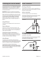
Electrical Requirements
The unit requires a 120V AC, 60Hz. 20A branch circuit.
The hood should only be connected to a dedicated circuit
(with ground) that has been installed according to relevant
regulations.
Figure 2: Typical Hood Installation
Cooking
Surface
* Follow cooking appliance manufacturer’s
recommendations
* 30" (762) min.
40" (1,016) max.
to Cooking Surface
* 30" (762) min.
40" (1,016) max.
to Cooking Surface
* 30" (762) min.
40" (1,016) max.
to Cooking Surface
Electrical
Zone
7½"
7½"
7½"
(190)
(190)
18"
18"
18"
(457)
(457)
(457)
inches (millimeters)
Weight
Hood, Filters, Grease Trays, and Spacers 104 lb (47 kg)
Integral Blower Model VTN1090 23 lb (11 kg)
IMPORTANT:
The supplied weights address only the ventilation unit
and blower. Installer must account for weight of any
materials of construction when calculating the total dead
weight load of installation, including but not limited to:
wall, tile, mortar, plaster, brick, finishes, partitions, and
other similarly incorporated architectural and structural
items. It is the responsibility of the owner and the installer
to determine if additional requirements and/or standards
apply to specific installations.
Table 1: Unit Weight with Blower

Installation Instructions English | 8 |
When connected to a GFCI-protected supply,
THERMADOR PROFESSIONAL
®
hoods are suitable for
use in damp locations that are protected from outside
weather conditions and not subject to saturation with water
and other liquids, but can be subject to moderate degrees
of moisture (such as an outdoor covered patio or lanai
area). Refer to local codes, NEC/CEC, and or the Authority
Having Jurisdiction (AHJ) for additional information.
Check your local building codes for proper method of
installation. In the U.S., if there are no applicable local
codes, this unit should be installed in accordance with the
National Electric Code ANSI/NFPA No. 70, Current Issue.
In Canada, installation must be in accordance with the CAN
1- B149.1 and .2 - Installation Codes for Gas Burning
Appliances and/or local codes.
The appliance must be grounded. In the event of an
electrical short circuit, grounding reduces the risk of electric
shock by providing a wire that allows the electric current to
escape.
Electrical Data on the Data Rating Plate
Data, including the model and serial number, is located on
the product data rating plate inside the appliance, visible
after removal of the filter frame (see Figure 30 on page 20).
Ductwork Preparation
Discharge Direction
The hood can be mounted on a wall or suspended from a
cabinet. Both vertical and horizontal discharge are possible
with either mounting method.
Ducting Recommendations
Proper performance is dependent upon proper ducting.
Local building codes may require the use of make-up air
systems when using ducted ventilation systems greater
than specified cubic feet per minute (CFM) of air
movement. The specified CFM varies from locale to locale.
It is the responsibility of the owner and the installer to
determine if additional requirements and/or standards
apply to specific installations.
DO NOT USE FLEXIBLE DUCT; it creates back pressure/
air turbulence and reduces performance. Always use metal
ductwork.
Always install a metal vent cover where the ductwork exits
the house. Hood must be vented to the outside of
building only.
COLD WEATHER installations should have an additional
backdraft damper installed to minimize backward cold air
flow and a nonmetallic thermal break to minimize
conduction of outside temperatures as part of the ductwork.
The damper should be on the cold air side of the thermal
break. The break should be as close as possible to where
the ducting enters the heated portion of the house.
MAKE-UP AIR: Local building codes may require the use
of make-up air systems when using ducted ventilation
systems greater than specified CFM of air movement. The
specified CFM varies from locale to locale. It is the
responsibility of the owner and the installer to determine if
additional requirements and/or standards apply to specific
installations.
For safety reasons, ducting should vent directly outdoors
(not into an attic, underneath the house, into the garage or
into any enclosed space). The unit cannot be used in
conjunction with a recirculation unit.
THERMADOR
®
recommends not exceeding 50 ft
(15.24 m) equivalent length of duct.
NOTE: The 25 ft. Blower Connector Cable accessory
(EXTNCB2) will only work for distances up to 25 ft. DO
NOT use more than one Blower Connector Cable per
installation.
Keep duct runs as short and straight as possible. Elbows
and transitions fittings reduce air flow efficiency. Back to
back elbows and “S” turns give very poor delivery and are
not recommended.
A short straight length of duct at the inlet of a remote
blower gives the best delivery.
Hoods are supplied with a 10" (254 mm) round transition. A
locally supplied transition is required for other sizes.
Use Table 2 on page 9 to compute permissible lengths for
duct runs to outdoors.
WARNING
The appliance must be grounded.

Installation Instructions English | 9 |
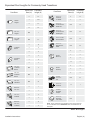
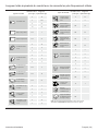
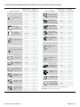
Equivalent Duct Lengths for Commonly Used Transitions
Smooth
Straight
6 1.2
7 0.95
8 0.7
10 0.6
3¼" x 10"
Straight
N/A 1
3¼" x 14"
Straight
N/A 0.7
90° Elbow
Round
612
78
86
45° Elbow
Round
65
74
83
3¼" x 10"
90° Elbow
Round
N/A 5
3¼” x 10"
45° Elbow
Round
N/A 15
3¼" x 10"
Flat Elbow
N/A 20
Round to
3¼" x 10"
61
71
3¼" x 10"
to Round
65
73
Round to
3¼" x 10"
90° Elbow
610
78
3¼" x 10"
to Round
90° Elbow
610
75
3¼" x 10"
Center Reverse
Elbow Left
N/A 15
3¼" x 10"
Center Reverse
Elbow Right
N/A 25
3¼" x 10" Left
Reverse Elbow
N/A 15
3¼" x 10"
Right Reverse
Elbow
N/A 25
Round
Wall Cap
62
72
82
10 2
Round
Roof Cap
62
72
82
2' Long
3¼" x 10"
Flex
N/A 20
3¼" x 10"
to Round
10 1
7" Inline
Backdraft
Damper
7
3¼" x 10"
Roof Jack
and Shutter
N/A
NOTE: These commonly used installation parts can be purchased
at a local hardware store. THERMADOR® does not manufacture all
these parts.
Duct Piece
Size of Duct
Piece (in)
Duct Piece
Size of Duct
Piece (in)
Equivalent
Length (ft)
Equivalent
Length (ft)
Table 2: Duct Lengths

Installation Instructions English | 10 |
Choosing the Correct Blower
It is recommended to use only THERMADOR blowers with
THERMADOR ventilation hoods. Consult the Ventilation
Planning Guide for recommended blowers. Contact
Customer Service for additional options (see the back page
for contact information).
IMPORTANT: Cutting off a connector to the appliance,
blower, or to the extension cable kit will void the warranty.
Blower selection will vary based on the volume of air that
needs to be moved and the length and location of the duct
run. For long duct runs with multiple turns and bends,
consider using a more powerful blower. For the most
efficient air-Àow exhaust, use a straight run or as few
elbows as possible (refer to “Ductwork Preparation” on
page 8).
Integral Blowers
These blowers are integrated into the hood at the time of
installation.
Remote Blowers
Depending on preference and ducting situation, these
blowers can be mounted on the roof or exterior wall of the
home. An exterior installation may be more appealing to
reduce noise in the kitchen.
The 25 ft. Blower Connector Cable Accessory
(EXTNCB25) is available to connect the hood to the
Remote Blower for distances up to 25 ft. Accessory cable
must be purchased separately. DO NOT use more than
one Blower Connector Cable per installation.
Inline Blowers
To minimize noise in the kitchen, these blowers are
mounted along the duct line anywhere between the kitchen
and the exterior wall. If there is easy access to duct line (in
an attic, for example), this may be an appealing option.
The 25 ft. Blower Connector Cable Accessory
(EXTNCB25) is available to connect the hood to the Inline
Blower for distances up to 25 ft. Accessory cable must be
purchased separately. DO NOT use more than one Blower
Connector Cable per installation.
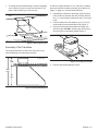
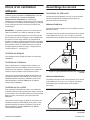
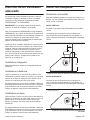
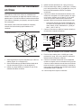
Hood Transition
Discharge Direction
The hood can be mounted on a wall or suspended from a
cabinet. Both vertical and horizontal discharge are possible
with either mounting method.
VERTICAL DISCHARGE
The hood is shipped ready for vertical discharge.
The transition supplied with the hood connects to standard
10-inch round duct. Figure 3 shows the transition
connected for vertical discharge.
HORIZONTAL DISCHARGE
The transition supplied with the hood connects to standard
10-inch round duct. Figure 4 shows the transition
connected for horizontal discharge.
Figure 3: Transition Centerline for Vertical Discharge
Figure 4: Transition Centerline for Horizontal Discharge
18"
(457)
6"
(152)
7½"
(190)
7½"
(190)
7½"
(190)
inches (mm)
7½"
(190)
10"
(255)
inches (mm)

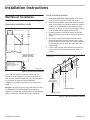
Installation Instructions English | 11 |
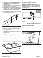
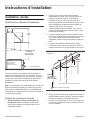
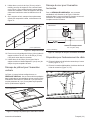
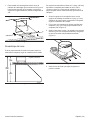
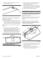
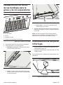
1. To change to horizontal discharge, move the discharge
cover, shown in Figure 5, to the top of the hood. The
plate is held in place by (4) 3/8'' hex nuts.
Assembly of the Transition
The supplied transition mounts to the top or rear of the
hood, depending on the discharge direction.
A minimum height clearance of 7½'' (190 mm) is needed
above the hood for transition mounting. See “Before You
Begin” on page 5 for overall hood dimensions.
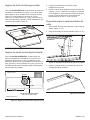
2. Depending on direction of discharge, align mounting
holes at base of transition with the mounting holes of
the ½'' (13 mm) flange located at the top or rear of the
hood.
3. Fasten transition to hood using four (4) 1/4'' (6 mm)
sheet metal screws included with hood (Figure 7).
4. Seal connection between transition and hood with
aluminum tape. DO NOT use duct tape. Ensure that
the connection is completely sealed (Figure 7).
5. Remove tape holding damper closed.
Figure 5: Discharge Direction
Figure 6: Transition Dimensions
7½"
(190)
7½"
(190)
7½"
(190)
25½"
(647)
25½"
(647)
25½"
(647)
18"
(457)
18"
(457)
18"
(457)
inches (mm)
Figure 7: Transition Connection

Installation Instructions English | 12 |
Installation Instructions
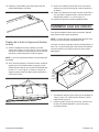
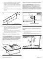
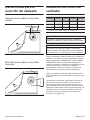
Wall Mount Installation
Determine installation height
Figure 8 shows a typical installation of the hood. The
installation height ranges from a minimum height of 30''
(762 mm) to a maximum height of 40'' (1016 mm); however,
it is necessary to follow the cooking appliance
manufacturer’s installation instructions for proper hood
height.
NOTICE: The hood could incur some damage from heat if
a THERMADOR PROFESSIONAL
®
series range or
rangetop is operated with multiple burners at high settings
under a hood that is installed at minimum clearances.
Hood mounting bracket
1. Turn power OFF at the service panel. Lock service
panel to prevent power from being turned ON.
2. After the hood installation height has been determined,
draw a horizontal line at a distance above the cooktop
equal to the recommended hood installation height
plus 16½'' (419 mm). This line is the mounting location
of the wooden bracket shipped with the hood.
3. Find the centerline of the hood. Draw a vertical line
along this centerline up to the horizontal line drawn in
Step 2.
4. The hood is mounted to the wall using the wooden
bracket shipped with the hood. Remove the wooden
bracket located at the top side of the hood by removing
the two shipping screws. Mark the center line of the
wood bracket.
5. Locate a stud on both sides of the hood centerline to
use for mounting the wooden bracket as shown in
Figure 9.
Figure 8: Typical Hood Installation
18"
(457)
18"
(457)
18"
(457)
25½"
(647)
25½"
(647)
25½"
(647)
*Hood mounting Heights
Minimum 30" (762)
Maximum 40" (1016)
*Hood mounting Heights
Minimum 30" (762)
Maximum 40" (1016)
*Hood mounting Heights
Minimum 30" (762)
Maximum 40" (1016)
*Follow cooking
appliance manufacturer’s
recommendations
27" (687)
27" (687)
27" (687)
inches (mm)
Figure 9: Mounting the Wooden Bracket
Cooking Surface
Distance to
cooking surface
plus 16½" (419)
Distance to
cooking surface
plus 16½" (419)
Distance to
cooking surface
plus 16½" (419)
Wood
Bracket
(included)
Wood
Bracket
(included)
Wood
Bracket
(included)
3" (76)
screws
3" (76)
screws
3" (76)
screws
Cooktop Centerline
Cooktop Centerline
Cooktop Centerline
inches (mm)

Installation Instructions English | 13 |
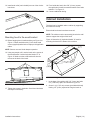
6. Align the top of the wood bracket along the horizontal
line drawn in Step 2. Align the centerlines of the
bracket and cooktop.
7. Drill a 3'' (76 mm) deep 3/16'' (3 mm) tap hole through
the wooden bracket, wall, and into the stud.
8. Use three, 3'' (76 mm) screws to attach the bracket to
the wall, as shown in Figure 9. For support of the hood,
use three studs. Countersink the screw heads to
prevent interference with the hood.
9. On the wood bracket, mark the locations used to hang
the hood according to Figure 10.
10. Drill a 3/16'' (4.8 mm) tap hole through the wooden
bracket and wall. These 5/8'' (16 mm) screws do not
need to go into the studs.
11. Use (2) 5/8'' (16 mm) screws to secure the wood
bracket leaving
¼'' (6 mm) of each screw exposed for
hanging the hood.
Vertical discharge ceiling cutout
VERTICAL DISCHARGE installations require a cutout in
the ceiling to accommodate 10'' (254 mm) duct and 5/8''
(16 mm) diameter clearance hole for ½'' (12.7 mm) conduit
to the j-box (Figure 11).
Horizontal discharge wall cutout
HORIZONTAL DISCHARGE installations require a wall
cutout, as shown in Figure 12, to provide clearance for the
transition. The location of the cutout is determined by the
hood installation height.
Prepare for the wire routing
12. Remove junction box channel covering the wires
(Figure 13, “A”).
13. Remove circular knockouts behind junction box
channel (Figure 13, “B”).
Figure 10: Hanging the Hood
Figure 11: Vertical Ceiling Cutout Dimensions
2 x 1½" (38) 2" (51)
28" (713)
28" (713)
28" (713)
28" (713)
28" (713)
28" (713)
inches (mm)
30
" (762)
30
" (762)
30
" (762)
6
" (152)
6
" (152)
6
" (152)
Conduit
Zone
Conduit
Zone
Conduit
Zone
12
" (305)
12
" (305)
12
" (305)
inches (mm)
Figure 12: Horizontal Wall Cutout Dimensions
Figure 13: Junction Box Channel
Back Wall
12"
(305)
7" (178)
7" (178)
7" (178)
Hood mounting heights
30"– 40" (762 –1016) from cooking surface.
Hood mounting heights
30"– 40" (762 –1016) from cooking surface.
Hood mounting heights
30"– 40" (762 –1016) from cooking surface.
Electric
Conduit
Zone
30
"
(762)
30
"
(762)
30
"
(762)
12
"
(305)
12
"
(305)
12
"
(305)
inches (mm)
“A”
“B”

Installation Instructions English | 14 |
14. Install strain relief (not included) into one of the circular
knockouts.
Mounting hood to the wood bracket
15. Before hanging hood, install transition per Figure 3 or
Figure 4. Fasten transition with (2) 3/8'' sheet metal
screws (supplied) and aluminum tape per all applicable
codes.
NOTE: Screws must not hinder damper operation.
16. Using two people to lift, rest the hood on the screws in
the wood bracket. Use the keyholes labeled "F" in
Figure 15. Make sure the wood bracket fits into the
recess on the back of the hood.
17. Tighten the screws in keyholes. Check hood levelness
and adjust if necessary.
18. From inside the hood, drive 5/8'' (16 mm) screws
through holes in hood into wooden bracket. See holes
labeled “J” in Figure 15.
19. Connect additional ducting.
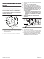
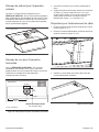
Cabinet Installation
The hood can be installed under a cabinet by supporting
the hood from the top.
Ensure both knockouts have been removed.
NOTE: The cabinet must be structurally joined to the wall
studs to support the weight of this hood.
Figure 16 shows the (4) keyholes labeled “K” used for
mounting the hood to the bottom of the cabinet.
1. In the base of the cabinet, drill 1/8'' (3 mm) tap holes
59'' (1,499 mm) apart, as indicated in Figure 16.
2. Screw in (4) 1" (25 mm) screws (provided with hood)
leaving 1/4'' (6 mm) exposed to hang the hood on.
Figure 14: Strain Relief
Figure 15: Location of Screw Holes
J
F
F
Figure 16: Tap Hole and Screw Hole Locations
“K” x4
“K” x4
L
“L” x2
“L” x2
1
9
/16
"
(40)
1
9
/16
"
(40)
1
9
/16
"
(40)
7
1
/16
"
(179)
(179)
(179)
59"
(1499)
59"
(1499)
59"
(1499)
inches (mm)

Installation Instructions English | 15 |
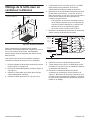
Vertical Discharge Cabinet Cutout
VERTICAL DISCHARGE installations require a cutout in
the ceiling to accommodate 10'' (254 mm) duct and 5/8''
(16 mm) diameter clearance hole for ½'' (12.7 mm) conduit
to the j-box (Figure 17).
Horizontal Discharge Cabinet Cutout
For HORIZONTAL DISCHARGE, use Figure 18 for the
geometry of the cutout required for clearance of the
transition. The location of the cutout is determined by the
hood installation height.
3. Hang hood from keyhole screws and tighten securely.
4. From inside of hood, insert screws supplied. Drill
through holes, use 5/8'' (16 mm) screws supplied, (1)
on each side and (6) along the front, into bottom of the
cabinet. See screw holes labeled "L" in Figure 16.
Prepare for the wire routing
1. Remove junction box channel covering the wires
(Figure 19, “A”).
2. Remove circular knockouts behind junction box
channel (Figure 19, “B”).
3. Install strain relief (not included) into one of the circular
knockouts.
Figure 17: Transition and Conduit Locations
Figure 18: Horizontal Wall Cutout Dimensions
30
" (762)
30
" (762)
30
" (762)
6
" (152)
6
" (152)
6
" (152)
Conduit
Zone
Conduit
Zone
Conduit
Zone
12
" (305)
12
" (305)
12
" (305)
inches (mm)
Back Wall
12"
(305)
7" (178)
7" (178)
7" (178)
Hood mounting heights
30"– 40" (762 –1016) from cooking surface.
Hood mounting heights
30"– 40" (762 –1016) from cooking surface.
Hood mounting heights
30"– 40" (762 –1016) from cooking surface.
Electric
Conduit
Zone
30
"
(762)
30
"
(762)
30
"
(762)
12
"
(305)
12
"
(305)
12
"
(305)
inches (mm)
Figure 19: Junction Box Channel
Figure 20: Strain Relief
“A”
“B”

Installation Instructions English | 16 |
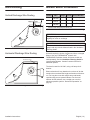
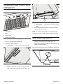
Wire Routing
Vertical Discharge Wire Routing
Horizontal Discharge Wire Routing
Blower Motor Installation
All hoods require the choice of a Remote, Inline, or Integral
Blower. Use only THERMADOR
®
blowers with
THERMADOR ventilation hoods. All blower models are
sold separately. See the Ventilation Planning Guide for
recommended blowers. Contact Customer Service for
additional options.
The hood is rated for 120 VAC, using a 20 amp circuit
breaker.
Blower selection will vary based on the volume of air that
needs to be moved and the length and location of the duct
run. For long duct runs with multiple turns and bends,
consider using a more powerful blower. For the most
efficient air-Àow exhaust, use a straight run or as few
elbows as possible (refer to “Ductwork Preparation” on
page 8).
Figure 21: Vertical Discharge
Figure 22: Horizontal Discharge
Route wires here
Route wires here
Route wires here
Blower SKU Voltage Current Circuit Breaker
Remote
VTR1330
a
120 8.8 20 amp
Inline
VTI1010
a
120 5.7 20 amp
Integral
VTN1090
a
120 5.4 20 amp
a
Indicates a letter designating the release year.
Table 3: Blower & Circuit Breaker Ratings
WARNING
Cutting the plug of the blower will void the warranty or
eligibility for return or exchange.
CAUTION
To reduce the risk of fire and electric shock, install this
range hood only with the blowers listed in the Ventilation
Planning Guide.

Installation Instructions English | 17 |
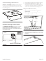
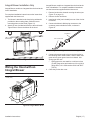
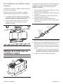
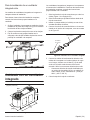
Integral Blower Installation Only
Integral Blower models are integrated into the hood at the
time of installation.
For complete installation instructions see the instructions
supplied with the blower unit.
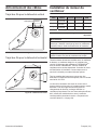
1. The blower is attached to the hood using weld studs
provided on the mounting plate. Guide the motor
mounting plate over the studs (Figure 23).
2. Attach (4) nuts (included with hood) to the weld studs.
Tighten nuts to secure the blower to the hood.
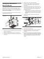
Wiring the Hood with an
Integral Blower
Integral Blower models are integrated into the hood at the
time of installation. For complete installation instructions
see the instructions supplied with the blower unit.
1. Remove junction box channel covering the wires (see
Figure 13 on page 13).
2. Remove circular knockouts.
3. Install strain relief (not included) into one of the circular
knockouts.
4. Connect the blower’s Molex plug connector to the
connector present inside the hood, as shown in
Figure 25.
5. Connect the power supply wires to the hood wires in
the following order: black to black, white to white, and
green wire to green ground screw on chassis. Use
spring type wire nuts.
• Spring type wire nuts rated for a minimum of two
(2) #18 gauge wires and maximum of four (4) #14
gauge wires, UL & CSA rated to 600V and 302°F
(150°C.)
6. Close the junction box cover.
Figure 23: Weld Stud Locations
Figure 24: Integral Blower Model
10⅞"
10⅞"
10⅞"
(275)
(275)
(275)
13⅛"
13⅛"
13⅛"
(335)
(335)
8¼"
(208)
8¼"
(208)
8¼"
(208)
18⅞"
18⅞"
18⅞"
(473)
(473)
inches (mm)
Figure 25: Wiring the Hood with an Integral Blower
From Control Panel
From Blower

Installation Instructions English | 18 |
Wiring the Hood with a
Remote Blower
Depending on preference and ducting situation, these
blowers can be mounted on the roof or exterior wall of the
home. An exterior installation may be more appealing to
reduce noise in the kitchen.
For complete installation instructions see the instructions
supplied with the blower unit.
1. Remove junction box channel covering the wires (see
Figure 13 on page 13).
2. Remove circular knockouts (Figure 13 on page 13).
3. Install strain relief (not included) into one of the circular
knockouts.
4. Install 1'' (25.4 mm) conduit connectors.
5. Run black, white, and green wires (#12 AWG) in 1''
(25.4 mm) conduit from the power supply to the
junction box.
6. Connect the power supply wires to the hood wires in
the following order: black to black, white to white, and
green wire to green ground screw on chassis. Use
spring type wire nuts.
• Spring type wire nuts, rated for a minimum of two
(2) #18 gauge wires and maximum of four (4) #14
gauge wires, UL & CSA rated to 600V and 302°F
(150°C).
7. Connect the “pigtail” to the connector inside the
junction box.
8. Close the junction box cover.
9. Run five (5) #14 AWG wires in 1'' (25.4 mm) conduit
from the remote blower to the second conduit
connector.
10. Connect the remote blower to the pigtail wires as per
Figure 27. Connect the remote blower green (ground)
wire to the ground screw in the junction box. Refer to
the blower installation instructions for further wiring
details.
Figure 26: Remote Blower
19⅞"
(505)
2⅛"
(54)
10"
(254)
2⅛"
(54)
20¾"
(527)
12⅞"
(327)
12⅛"
(308)
6½"
(165)
1⅞"
(48)
13⅝"
(346)
dia.
9⅞"
(251)
inches (mm)
Figure 27: Wiring the Hood with a Remote Blower
SPEED 1
SPEED 2
SPEED 3
NEUTRAL
RD
BU
BN
WH
SP4
GROUND
N
SP1
SP2
SP3
Brown
Brown
Brown
Green/Yellow
Green/Yellow
Green/Yellow
White
White
White
Red
Red
Red
Blue
Blue
Blue
Orange
Orange
Orange
WH / BC / BL (16 AWG)
BK / N / NE (16 AWG)
120V, 60HZ, 20A
POWER SUPPLY
L1NT1T2S3

Installation Instructions English | 19 |
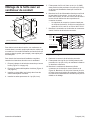
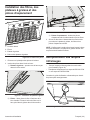
Wiring the Hood with an Inline
Blower
To minimize noise in the kitchen, these blowers are
mounted along the duct line anywhere between the kitchen
and the exterior wall. If there is easy access to duct line (in
an attic, for example), this may be an appealing option.
For complete installation instructions see the instructions
supplied with the blower unit.
1. Remove junction box channel covering the wires (see
Figure 13 on page 13).
2. Remove circular knockouts (Figure 13 on page 13).
3. Install strain relief (not included) into one of the circular
knockouts.
4. Install 1'' (25.4 mm) conduit connectors.
5. Run black, white, and green wires (#12 AWG) in 1''
(25.4 mm) conduit from power supply to junction box.
6. Connect the power supply wires to the hood wires in
the following order: black to black, white to white, and
green wire to green ground screw on chassis. Use
spring type wire nuts.
• Spring type wire nuts, rated for a minimum of two
(2 #18 gauge wires and maximum of four (4) #14
gauge wires, UL & CSA rated to 600V and 302°F
(150°C).
7. Connect the “pigtail” to the connector inside the
junction box.
8. Close the junction box cover.
9. Run five (5) wires (#14 AWG) in 1'' (25.4 mm) conduit
from the inline blower to the second conduit connector.
10. Connect the inline blower to the pigtail wires as per
Figure 29. Connect the inline blower green (ground)
wire to the ground screw in the junction box.
Figure 28: Inline Blower
12⅛"
(308)
14⅜"
(365)
⅞" (22)
1¾"
(44)
19⅛"
(486)
ø 9⅞"
(251)
12"
(305)
12⅞"
(327)
inches (mm)
Figure 29: Wiring the Hood with an Inline Blower
SPEED 1
SPEED 2
SPEED 3
NEUTRAL
RD
BU
BN
WH
SP4
GROUND
N
SP1
SP2
SP3
Brown
Brown
Brown
Green/Yellow
Green/Yellow
Green/Yellow
White
White
White
Red
Red
Red
Blue
Blue
Blue
Orange
Orange
Orange
WH / BC / BL (16 AWG)
BK / N / NE (16 AWG)
120V, 60HZ, 20A
POWER SUPPLY
L1NT1T2S3
A página está carregando...
A página está carregando...
A página está carregando...
A página está carregando...
A página está carregando...
A página está carregando...
A página está carregando...
A página está carregando...
A página está carregando...
A página está carregando...
A página está carregando...
A página está carregando...
A página está carregando...
A página está carregando...
A página está carregando...
A página está carregando...
A página está carregando...
A página está carregando...
A página está carregando...
A página está carregando...
A página está carregando...
A página está carregando...
A página está carregando...
A página está carregando...
A página está carregando...
A página está carregando...
A página está carregando...
A página está carregando...
A página está carregando...
A página está carregando...
A página está carregando...
A página está carregando...
A página está carregando...
A página está carregando...
A página está carregando...
A página está carregando...
A página está carregando...
A página está carregando...
A página está carregando...
A página está carregando...
A página está carregando...
A página está carregando...
-
 1
1
-
 2
2
-
 3
3
-
 4
4
-
 5
5
-
 6
6
-
 7
7
-
 8
8
-
 9
9
-
 10
10
-
 11
11
-
 12
12
-
 13
13
-
 14
14
-
 15
15
-
 16
16
-
 17
17
-
 18
18
-
 19
19
-
 20
20
-
 21
21
-
 22
22
-
 23
23
-
 24
24
-
 25
25
-
 26
26
-
 27
27
-
 28
28
-
 29
29
-
 30
30
-
 31
31
-
 32
32
-
 33
33
-
 34
34
-
 35
35
-
 36
36
-
 37
37
-
 38
38
-
 39
39
-
 40
40
-
 41
41
-
 42
42
-
 43
43
-
 44
44
-
 45
45
-
 46
46
-
 47
47
-
 48
48
-
 49
49
-
 50
50
-
 51
51
-
 52
52
-
 53
53
-
 54
54
-
 55
55
-
 56
56
-
 57
57
-
 58
58
-
 59
59
-
 60
60
-
 61
61
-
 62
62


Thermador PH60GS Guia de instalação
- Categoria
- Exaustores
- Tipo
- Guia de instalação
- Este manual também é adequado para
em outras línguas
- español: Thermador PH60GS Guía de instalación
- français: Thermador PH60GS Guide d'installation
- English: Thermador PH60GS Installation guide
Artigos relacionados
-
Thermador VCIN54GWS Guia de instalação
-
Thermador VTI610P Guia de instalação
-
-
-
-
Thermador PH48HWS Guia de usuario
-
-
Thermador 739334 Guia de usuario
-
Thermador UCVM36XS Instruções de operação
-
Outros documentos
-
Bosch HUI50351UC/01 Guia de instalação
-
Gaggenau AI 442 Guia de instalação
-
Fagor 60CFP-36IX User & Installation Manual (1.00 MB)
-
-
Kenmore Elite 79044113510 Guia de instalação
-
Broan B5936SS Guia de instalação
-
Sub-Zero PWC482418 Guia de instalação
-
 Kenmore Elite 23355802110 Manual do proprietário
-
Haier HHX7130 Manual do usuário
-
Jenn-Air JED3430GB Guia de instalação
