Haworth 7021-7644c Instruções de operação
- Tipo
- Instruções de operação

Part No: Rev:
Page:
E.C.O. No: 305-004 1 O F 5 7021-7644 C
CUSTOMER SERVICE PHONE: 1-800-426-8562
VANCOUVER
®
by SM ED
BASE FEED
(single circuit applications)
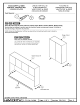
Installation Instructions
Tools Required
#2
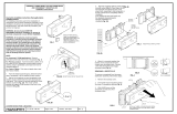
W ARNIN G : Do not electrically interconnect m odular pow er distribution system s pow ered from tw o different
pow er feed units. This poses a S H O C K H A ZA R D to service personnel and w ill c a u s e R IS K O F F IR E d u e to
excessive circulating currents.
W ARNIN G : A ll circuit pow er M UST R EM AIN DISCO NNECTED during any installation or rem oval of electrical
com ponents and racew ay covers to avoid SH O C K H A ZA R D S.
NOTE: C onnections of this m odular pow er distribution com ponent M U S T be done by a licensed electrician, w ho m ust
control the size and loading of each branch circuit. The person or group installing H aw orth products is responsible for
com plying w ith all applicable building and electrical code requirem ents.
NOTE: R acew ays that are electrically connected m ust also be m echanically connected. The com bined length for a
cord-connectedsystem m ay not exceed 30 feet.
ADVERTENCIA: N o se deben interconectar eléctricam ente sistem as m odulares de distribución de corriente, que reciben la
energía de m ódulos de alim entación diferentes. Esto presenta un PELIG R O D E C H O Q U E para el personal de servicio y
provocaría un R IESG O D E IN C EN D IO debido a las corrientes excesivas en circulación.
ADVERTENCIA: La corriente a todos los ram ales del circuito DEBERA PERM ANECER DESCONECTADA durante la
instalación o rem oción de los com ponentes eléctricos y las tapas de los rieles para evitar PELIG R O S DE C H O Q U E.
NOTA: Las conexiones de este com ponente m odular de distribución de corriente DEBERA hacerlas un electricista certificado,
quien deberá controlar el tam año y la carga de cada ram al del circuito. La persona o grupo que instale los productos H aw orth
es responsable de cum plir con todos los requisitos aplicables de los códigos de construcción y electricidad.
NOTA:
Los rieles que estén conectados eléctricam ente, tam bién deberán estar conectados m ecánicam ente. La longitud
com binada para un sistem a de conexión con cables no deberá exceder 30 pies.
AVERTISSEM ENT :
N e pas raccorder électriquem ent des circuits de distribution de puissance électrique m odulaires alim entés
par deux unités d'alim entation différentes car cela présente un RISQUE DE SECOUSSE ÉLECTRIQUE pour le personnel
d'entretien et un R ISQ U E D 'IN C EN D IE en raison de la présence de courants de circulation trop im portants.
AVERTISSEM ENT : Laisser TOUS LES CIRCUITS DÉBRANCHÉS pendant le montage ou le démontage de composants
électriques et de couvercles de conduites pour éviter les risques de SECOUSSE ÉLECTRIQUE.
NOTE:
Les raccordem ents de cet élém ent de distribution de puissance électrique m odulaire D O IVEN T ÊTR E réalisés par un
électricien agréé qui doit vérifier la section et la charge de toutes les dérivations du circuit. La personne ou le groupe installant
les produits H aw orth est responsable de la conform ité aux codes du bâtim ent et électriques nationaux et locaux applicables.
NOTE:
Les conduites de câbles qui sont raccordées électriquem ent doivent aussi lêtre m écaniquem ent. La longueur totale
dun systèm e raccordé par cordons ne doit pas dépasser 10 m (30 pieds).
ALIM ENTATION PAR LA BASE
VANCOUVER
®
by SM ED
(Pour utilisations à un seul circuit)
N otice de m ontage
BASE DE ALIM ENTACION
VANCOUVER
®
by SM ED
(aplicaciones para un solo
circuito sim ple)
Instrucciones de Instalación

Part No: Rev:
Page:
E.C.O. No: 305-004 2 O F 5 7021-7644 C
CUSTOMER SERVICE PHONE: 1-800-426-8562
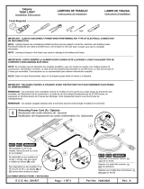
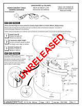
#10-24 x .38" Screw
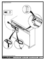
HARDWIRE BASEFEED

Part No: Rev:
Page:
E.C.O. No: 305-004 3 O F 5 7021-7644 C
CUSTOMER SERVICE PHONE: 1-800-426-8562
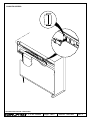
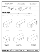
CONDUIT BASEFEED

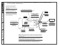
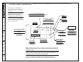
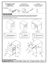
NOTE:
IF USING A SHARED NEUTRAL CONDUCTOR THE CONDUCTOR MUST BE
PROPERLY SIZED TO SAFELY CARRY CURRENT FROM UNBALANCED AND/OR
NONLINEAR LOADS.
BUILDING OR ASSEM BLY
JUNCTION BOX
SEE NO TE
L1
N
This figure shows a wiring diagram to
connect the six (6) wire Infeed in a
208Y/120 volt, 3-phase, shared neutral
configuration.
Part No: Rev:
Page:
E.C.O. No: 305-004 4 O F 5 7021-7644 C
CUSTOMER SERVICE PHONE: 1-800-426-8562
TO M AIN SERVICE PANEL
GROUND BAR
SUB PANEL
15 OR 20 AMP CIRCUIT BREAKERS
METAL RACEW AY
BLACK (L1)
WHITE (N1)
GREEN (GRD) OR
BARE COPPER
ELECTRICAL W IRING CONFIGURATIONS /
CONFIGURACIONES DEL ALAMBRADO ELECTRICO / SCHÉM AS ÉLECTRIQUES
AL PANEL PRINCIPAL DE
SERVICIO
VERS LE PANNEAU
PRINCIPAL
D'ALIM ENTATION
ROMPEDORES DE CIRCUITO DE 15 O 20 AMPERES
SUB-PANEL
SOUS-PANNEAU
NEGRO (L1)
N O IR (L 1 )
BLANCO (N1)
BLANC (N1)
VERDE (TIERRA) O
CO BRE PELADO
VERT (TERRE )
OU CUIVRE NU
BARRA DE TIERRA
BARRE DE TERRE
G U IA M E T A L IC A
CONDUITE MÉTALLIQUE
COUPE-CIRCUIT DE 15 OU 20 A
CAJA DE CONEXIONES DEL
EDIFICIO O DEL CONJUNTO
BOÎTE DE RACCORDEMENT DU
BÂTIMENT OU DE LENSEMBLE
VANCOUVER®
BASE FEED
BASE DE ALIM ENTACION
VANCO UVER
®
ALIM ENTATIO N PAR LA
BASE VANCOUVER
®
LIQUID-TIGHT
CONDUIT
CABLE A PRUEBA
D E L IQ U ID O S
CONDUIT ÉTANCHE
AUX LIQUIDES
VOIR NO TE
VER NOTA
NOTA:
SI SE USA CONDUCTOR NEUTRAL COMPARTIDO, EL CONDUCTOR DEBERA
TENER EL TAMAÑO CORRECTO PARA LLEVAR LA CORRIENTE DE CARGAS
DESBALANCEADAS O NO LINEALES EN FORMA SEGURA.
NOTE:
EN CAS DE CONDUCTEUR NEUTRE PARTAGÉ, CELUI-CI DOIT ÊTRE FUNE
SECTION SUFFISANTE POUR PERMETTRE DE TRANSPORTER EN TOUTE
SÉCURITÉ LE COURANT PROVENANT DUNE CHARGE NON ÉQUILIBRÉE ET/OU
Esta figura m uestra el diagram a de cableado
para conectar los seis (6) cables de
alim entación en una configuración neutral
com partida de 208Y/120 voltios, 3 fases.
C ette figure est le schém a de câblage du
raccordem ent de six (6) fils dalim entation
dans une configuration 208 V étoile / 120 V
triphasé à neutre partagé.

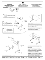
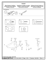
NOTE:
IF USING A SHARED NEUTRAL CONDUCTOR THE CONDUCTOR MUST BE
PROPERLY SIZED TO SAFELY CARRY CURRENT FROM UNBALANCED AND/OR
NONLINEAR LOADS.
BUILDING OR ASSEM BLY
JUNCTION BOX
SEE NO TE
L1
N
This figure shows a wiring diagram to
connect the three (3) wire Infeed in a
208Y/120 volt, 3-phase, shared neutral
configuration.
Part No: Rev:
Page:
E.C.O. No: 305-004 5 O F 5 7021-7644 C
CUSTOMER SERVICE PHONE: 1-800-426-8562
TO M AIN SERVICE PANEL
GROUND BAR
SUB PANEL
15 OR 20 AMP CIRCUIT BREAKERS
METAL RACEW AY
BLACK (L1)
WHITE (N1)
GREEN (GRD) OR
BARE COPPER
ELECTRICAL W IRING CONFIGURATIONS /
CONFIGURACIONES DEL ALAMBRADO ELECTRICO / SCHÉM AS ÉLECTRIQUES
AL PANEL PRINCIPAL DE
SERVICIO
VERS LE PANNEAU
PRINCIPAL
D'ALIM ENTATION
ROMPEDORES DE CIRCUITO DE 15 O 20 AMPERES
SUB-PANEL
SOUS-PANNEAU
NEGRO (L1)
N O IR (L 1 )
BLANCO (N1)
BLANC (N1)
VERDE (TIERRA) O
CO BRE PELADO
VERT (TERRE )
OU CUIVRE NU
BARRA DE TIERRA
BARRE DE TERRE
G U IA M E T A L IC A
CONDUITE MÉTALLIQUE
COUPE-CIRCUIT DE 15 OU 20 A
CAJA DE CONEXIONES DEL
EDIFICIO O DEL CONJUNTO
BOÎTE DE RACCORDEMENT DU
BÂTIMENT OU DE LENSEMBLE
VANCOUVER®
BASE FEED
BASE DE ALIM ENTACION
VANCO UVER
®
ALIM ENTATIO N PAR LA
BASE VANCOUVER
®
LIQUID-TIGHT
CONDUIT
CABLE A PRUEBA
D E L IQ U ID O S
CONDUIT ÉTANCHE
AUX LIQUIDES
VOIR NO TE
VER NOTA
NOTA:
SI SE USA CONDUCTOR NEUTRAL COMPARTIDO, EL CONDUCTOR DEBERA
TENER EL TAMAÑO CORRECTO PARA LLEVAR LA CORRIENTE DE CARGAS
DESBALANCEADAS O NO LINEALES EN FORMA SEGURA.
NOTE:
EN CAS DE CONDUCTEUR NEUTRE PARTAGÉ, CELUI-CI DOIT ÊTRE FUNE
SECTION SUFFISANTE POUR PERMETTRE DE TRANSPORTER EN TOUTE
SÉCURITÉ LE COURANT PROVENANT DUNE CHARGE NON ÉQUILIBRÉE ET/OU
Esta figura m uestra el diagram a de cableado
para conectar los tres (3) cables de
alim entación en una configuración neutral
com partida de 208Y/120 voltios, 3 fases.
C ette figure est le schém a de câblage du
raccordem ent de trois (3) fils dalim entation
dans une configuration 208 V étoile / 120 V
triphasé à neutre partagé.
-
 1
1
-
 2
2
-
 3
3
-
 4
4
-
 5
5


Haworth 7021-7644c Instruções de operação
- Tipo
- Instruções de operação
Artigos relacionados
-
 Haworth 7021-7612d Instruções de operação
-
 Haworth 7029-9524a Instruções de operação
-
 Haworth 7029-9525a Instruções de operação
-
 Haworth 7029-9488b Instruções de operação
-
 Haworth 7021-8209c Instruções de operação
-
 Haworth 7021-6742 Instruções de operação
-
 Haworth 7021-7630f Instruções de operação
-
 Haworth 7021-7592d Instruções de operação
-
 Haworth 7021-6730e Instruções de operação
-
 Haworth 7021-7643e Instruções de operação


