Makita DHR183 Cordless Rotary Hammer Manual do usuário
- Tipo
- Manual do usuário

DHR183
EN Cordless Rotary Hammer INSTRUCTION MANUAL 8
FR Perforateur Sans Fil MANUEL D’ INSTRUCTIONS 18
DE Akku-Bohrhammer BETRIEBSANLEITUNG 29
IT Martello rotativo a batteria ISTRUZ IONI PER L’ USO 41
NL Accuboorhamer GEBRUIKSAANW IJZ ING 53
ES Martillo Rotativo Inalámbrico MANUAL DE
INSTRUCCIONES 64
PT Martelete Rotativo a Bateria MANUAL DE INSTRUÇÕ ES 75
DA Akku-borehammer BRUGSANVISNING 86
EL Φορητό σφυροτρύπανο ΕΕΙΙΔΙ ΔΗΙΝ 96
TR Akülü Kırıcı Delc KULLANMA KILAVUZ U 107

2
1
2
3
Fig.1
1
2
Fig.2
1
Fig.3
1
Fig.4
1
AB
Fig.5
1
Fig.6
1
Fig.7
1
Fig.8

3
1
Fig.9
1
2
Fig.10
1
Fig.11
1
2
Fig.12
3
1 2
4
Fig.13
1
Fig.14
2
1
Fig.15

4
1
2
3
Fig.16
1
Fig.17
1
2
Fig.18
1
Fig.19
1
Fig.20
1
2
1
2
Fig.21
1
2
Fig.22

5
1
2
35
4
Fig.23
2
1
Fig.24
1
Fig.25
Fig.26
Fig.27
1
2
3
4
Fig.28

6
4
3
1
2
Fig.29
1
2
Fig.30
1
Fig.31
1
Fig.32
Fig.33
1
Fig.34
1
Fig.35
1
2
Fig.36

7
1
2
3
4
Fig.37
1
2
4
3
Fig.38
2
1
3
4
5
Fig.39
1
2
3
Fig.40
Fig.41
12
Fig.42
Fig.43
Fig.44

8ENGLISH
ENGLISH (Original instructions)
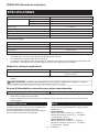
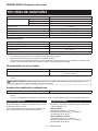
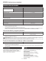
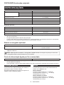
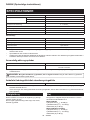
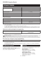
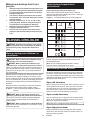
SPECIFICATIONS
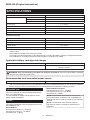
Model: DHR183
Dr i l l i n g c a p a c i t i e s C o n c r e t e 18 m m
S t e e l 13 m m
W o o d 24 m m
N o l o a d s p e e d 0 - 1, 100 m i n -1
B l o w s p e r m i n u t e 0 - 5, 000 m i n -1
O v e r a l l l e n g t h ( w i t h B L 186 0B ) 288 m m
R a t e d v o l t a g e D.C . 18 V
N e t w e i g h t 2.1 - 2.9 k g
Optional accessory
Model: DX 16
S u c t i o n p e r f o r m a n c e 0.24 l / m i n
O p e r a t i n g s t r o k e U p t o 105 m m
S u i t a b l e d r i l l b i t U p t o 16 5 m m
N e t w e i g h t 0.77 k g
Due to our continuing program of research and development, the specications herein are subject to change
w i t h o u t n o t i c e .
Specications may dier from country to country.
The weight may dier depending on the attachment(s), including the battery cartridge. The lightest and heavi-
e s t c o m b i n a t i o n s , a c c o r d i n g t o EP T A-P r o c e d u r e 01/ 2014 , a r e s h o w n i n t h e t a b l e .
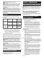
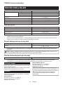
Applicable battery cartridge and charger
Battery cartridge B L 1815N / B L 1820B / B L 1830B / B L 184 0B / B L 1850B / B L 186 0B
C harger DC 18R C / DC 18R D / DC 18R E / DC 18S D / DC 18S E / DC 18S F /
DC 18S H / DC 18W C
•
Some of the battery cartridges and chargers listed above may not be available depending on your region of residence.
WARNING: Only use the battery cartridges and chargers listed above. Use of any other battery cartridges
and chargers may cause injury and/or re.
Recommended cord connected pow er source
P o r t a b l e p o w e r p a c k P DC 01
The cord connected power source(s) listed above may not be available depending on your region of residence.
Before using the cord connected power source, read instruction and cautionary markings on them.
Intended use
T h e t o o l i s i n t e n d e d f o r h a m m e r d r i l l i n g a n d d r i l l i n g i n
b r i c k , c o n c r e t e a n d s t o n e .
It i s a l s o s u i t a b l e f o r d r i l l i n g w i t h o u t i m p a c t i n w o o d ,
m e t a l , c e r a m i c a n d p l a s t i c .
Noise
The typical A-weighted noise level determined accord-
i n g t o EN 6 284 1-2-6 :
Model DHR183
S o u n d p r e s s u r e l e v e l ( L p A) : 9 0 d B ( A)
S o u n d p o w e r l e v e l ( L W A) : 101 d B ( A)
Uncertainty (K) :dB (A)
Model DHR183 w ith DX 16
S o u n d p r e s s u r e l e v e l ( L p A) : 9 0 d B ( A)
S o u n d p o w e r l e v e l ( L W A) : 101 d B ( A)
Uncertainty (K) :dB(A)
NOTE: T h e d e c l a r e d n o i s e e m i s s i o n v a l u e ( s ) h a s
b e e n m e a s u r e d i n a c c o r d a n c e w i t h a s t a n d a r d t e s t
method and may be used for comparing one tool with
another.
NOTE: T h e d e c l a r e d n o i s e e m i s s i o n v a l u e ( s )
may also be used in apreliminary assessment of
exposure.

9ENGLISH
WARNING: W ear ear protection.
WARNING: The noise emission during actual
use of the power tool can dier from the declared
value(s) depending on the w ays in w hich the
tool is used especially w hat kind of w orkpiece is
processed.
WARNING: Be sure to identify safety mea-
sures to protect the operator that are based on an
estimation of exposure in the actual conditions of
use (taking account of all parts of the operating
cycle such as the times w hen the tool is sw itched
o and when it is running idle in addition to the
trigger time).
Vibration
T h e f o l l o w i n g t a b l e s h o w s t h e v i b r a t i o n t o t a l v a l u e
( t r i -a x i a l v e c t o r s u m ) d e t e r m i n e d a c c o r d i n g t o a p p l i c a -
ble standard.
W ork mode Vibration
emission
Uncertainty (K)
Applicable
standard /
Test condition
H a m m e r
d r i l l i n g i n t o
c o n c r e t e
( a h , H D)
7.5 m / s 21.5 m / s 2EN 6 284 1-2-6
7.5 m / s 21.5 m / s 2
R e c o m m e n d e d
p r a c t i c a l
operation*
H a m m e r
d r i l l i n g i n t o
c o n c r e t e w i t h
DX 16 ( a h , H D)
7.6 m / s 21.7 m / s 2EN 6 284 1-2-6
7.7 m / s 21.5 m / s 2
R e c o m m e n d e d
p r a c t i c a l
operation*
* T h e t e s t c o n d i t i o n o f r e c o m m e n d e d p r a c t i c a l o p e r a t i o n
m e e t s EN 6 284 1-2-6 , e x c e p t f o r t h e f o l l o w i n g p o i n t s :
•F e e d f o r c e i s a p p l i e d t o t h e s w i t c h h a n d l e ( m a i n
handle) for working accuracy and eciency.
The side grip/handle (auxiliary handle) is held to
keep balance of the tool.
NOTE: T h e d e c l a r e d v i b r a t i o n t o t a l v a l u e ( s ) h a s b e e n
m e a s u r e d i n a c c o r d a n c e w i t h a s t a n d a r d t e s t m e t h o d
and may be used for comparing one tool with another.
NOTE: The declared vibration total value(s) may also
be used in apreliminary assessment of exposure.
WARNING: The vibration emission during
actual use of the power tool can dier from the
declared value(s) depending on the w ays in w hich
the tool is used especially w hat kind of w orkpiece
is processed.
WARNING: Be sure to identify safety mea-
sures to protect the operator that are based on an
estimation of exposure in the actual conditions of
use (taking account of all parts of the operating
cycle such as the times w hen the tool is sw itched
o and when it is running idle in addition to the
trigger time).
Declarations of Conformity
For European countries only
The Declarations of conformity are included in Annex A
t o t h i s i n s t r u c t i o n m a n u a l .
SAFETY W ARNINGS
General pow er tool safety w arnings
WARNING Read all safety w arnings, instruc-
tions, illustrations and specications provided with
this pow er tool. F a i l u r e t o f o l l o w a l l i n s t r u c t i o n s l i s t e d
below may result in electric shock, re and/or serious
injury.
Save all w arnings and instruc-
tions for future reference.
The term power tool in the warnings refers to your
mains-operated (corded) power tool or battery-operated
( c o r d l e s s ) p o w e r t o o l .
CORDLESS ROTARY HAMMER
SAFETY W ARNINGS
Safety instructions for all operations
1. W ear ear protectors. Ex p o s u r e t o n o i s e c a n
c a u s e h e a r i n g l o s s .
2. Use auxiliary handle(s), if supplied w ith the
tool. Loss of control can cause personal injury.
3.
Hold the pow er tool by insulated gripping sur-
faces, w hen performing an operation w here the
cutting accessory may contact hidden w iring.
Cutting accessory contacting alive wire may
m a k e e x p o s e d m e t a l p a r t s o f t h e p o w e r t o o l " l i v e "
a n d c o u l d g i v e t h e o p e r a t o r a n e l e c t r i c s h o c k .
Safety instructions w hen using long drill bits w ith
rotary hammers
1. Alw ays start drilling at low speed and w ith the
bit tip in contact w ith the w orkpiece. At h i g h e r
speeds, the bit is likely to bend if allowed to rotate
freely without contacting the workpiece, resulting
in personal injury.
2. Apply pressure only in direct line w ith the bit
and do not apply excessive pressure. B i t s c a n
b e n d , c a u s i n g b r e a k a g e o r l o s s o f c o n t r o l , r e s u l t -
ing in personal injury.
Additional safety w arnings
1. W ear a hard hat (safety helmet), safety glasses
and/or face shield. Ordinary eye or sun glasses
are NOT safety glasses. It is also highly recom-
mended that you w ear a dust mask and thickly
padded gloves.
2. Be sure the bit is secured in place before
operation.
3. Under normal operation, the tool is designed
to produce vibration. The screw s can come
loose easily, causing a breakdow n or accident.
Check tightness of screw s carefully before
operation.
4 . In cold w eather or w hen the tool has not been
used for a long time, let the tool w arm up for
a w hile by operating it under no load. This
w ill loosen up the lubrication. W ithout proper
warm-up, hammering operation is dicult.
5. Always be sure you have a rm footing. Be
sure no one is below w hen using the tool in
high locations.

10 ENGLISH
6 . Hold the tool rmly with both hands.
7. Keep hands aw ay from moving parts.
8. Do not leave the tool running. Operate the tool
only w hen hand-held.
9 . Do not point the tool at any one in the area
when operating. The bit could y out and
injure someone seriously.
10.
Do not touch the bit, parts close to the bit, or
w orkpiece immediately after operation; they may
be extremely hot and could burn your skin.
11. Some material contains chemicals w hich may
be toxic. Take caution to prevent dust inhala-
tion and skin contact. Follow material supplier
safety data.
12. Alw ays be sure that the tool is sw itched
o and the battery cartridge and the bit are
removed before handing the tool to other
person.
13. Before operation, make sure that there is no
buried object such as electric pipe, w ater pipe
or gas pipe in the w orking area. O t h e r w i s e , t h e
drill bit/chisel may touch them, resulting an electric
s h o c k , e l e c t r i c a l l e a k a g e o r g a s l e a k .
14 . Do not operate the tool at no-load
unnecessarily.
SAVE THESE INSTRUCTIONS.
WARNING: DO NOT let comfort or familiarity
w ith product (gained from repeated use) replace
strict adherence to safety rules for the subject
product. MISUSE or failure to follow the safety
rules stated in this instruction manual may cause
serious personal injury.
Important safety instructions for
battery cartridge
1. Before using battery cartridge, read all instruc-
tions and cautionary markings on (1) battery
charger, (2) battery, and (3) product using
battery.
2. Do not disassemble or tamper w ith the battery
cartridge. It may result in are, excessive heat,
o r e x p l o s i o n .
3. If operating time has become excessively
shorter, stop operating immediately. It may
result in a risk of overheating, possible burns
and even an explosion.
4 . If electrolyte gets into your eyes, rinse them
out w ith clear w ater and seek medical atten-
tion right aw ay. It may result in loss of your
eyesight.
5. Do not short the battery cartridge:
( 1) Do not touch the terminals w ith any con-
ductive material.
( 2) Avoid storing battery cartridge in a con-
tainer w ith other metal objects such as
nails, coins, etc.
( 3) Do not expose battery cartridge to w ater
or rain.
A battery short can cause a large current
ow, overheating, possible burns and even a
breakdow n.
6 . Do not store and use the tool and battery car-
tridge in locations w here the temperature may
reach or exceed 50 ° C (122 ° F).
7. Do not incinerate the battery cartridge even if
it is severely damaged or is completely w orn
out. The battery cartridge can explode in a re.
8. Do not nail, cut, crush, throw , drop the battery
cartridge, or hit against a hard object to the
battery cartridge. Such conduct may result in a
re, excessive heat, or explosion.
9 . Do not use a damaged battery.
10. The contained lithium-ion batteries are subject
to the Dangerous Goods Legislation require-
ments.
For commercial transports e.g. by third parties,
f o r w a r d i n g a g e n t s , s p e c i a l r e q u i r e m e n t o n p a c k -
aging and labeling m ust be observed.
F o r p r e p a r a t i o n o f t h e i t e m b e i n g s h i p p e d , c o n s u l t -
i n g a n e x p e r t f o r h a z a r d o u s m a t e r i a l i s r e q u i r e d .
Please also observe possibly more detailed
n a t i o n a l r e g u l a t i o n s .
Tape or mask o open contacts and pack up the
battery in such amanner that it cannot move
a r o u n d i n t h e p a c k a g i n g .
11. W hen disposing the battery cartridge, remove
it from the tool and dispose of it in a safe
place. Follow your local regulations relating to
disposal of battery.
12. Use the batteries only w ith the products
specied by Makita. In s t a l l i n g t h e b a t t e r i e s t o
non-compliant products may result in are, exces-
sive heat, explosion, or leak of electrolyte.
13. If the tool is not used for a long period of time,
the battery must be removed from the tool.
14 . During and after use, the battery cartridge may
take on heat w hich can cause burns or low
temperature burns. Pay attention to the han-
dling of hot battery cartridges.
15. Do not touch the terminal of the tool imme-
diately after use as it may get hot enough to
cause burns.
16 . Do not allow chips, dust, or soil stuck into the
terminals, holes, and grooves of the battery
cartridge. It may cause heating, catching re,
burst and malfunction of the tool or battery car-
tridge, resulting in burns or personal injury.
17. Unless the tool supports the use near
high-voltage electrical pow er lines, do not use
the battery cartridge near high-voltage electri-
cal pow er lines. It may result in amalfunction or
breakdown of the tool or battery cartridge.
18. Keep the battery aw ay from children.
SAVE THESE INSTRUCTIONS.
CAUTION: Only use genuine Makita batteries.
U s e o f n o n -g e n u i n e M a k i t a b a t t e r i e s , o r b a t t e r i e s t h a t
have been altered, may result in the battery bursting
causing res, personal injury and damage. It will
also void the Makita warranty for the Makita tool and
c h a r g e r .

11 ENGLISH
Tips for maintaining maximum
battery life
1. Charge the battery cartridge before completely
discharged. Alw ays stop tool operation and
charge the battery cartridge w hen you notice
less tool pow er.
2. Never recharge a fully charged battery car-
tridge. Overcharging shortens the battery
service life.
3. Charge the battery cartridge w ith room tem-
perature at 10 ° C - 40 ° C (50 ° F - 104 ° F). Let
a hot battery cartridge cool dow n before
charging it.
4 . W hen not using the battery cartridge, remove
it from the tool or the charger.
5. Charge the battery cartridge if you do not use
it for a long period (more than six months).
FUNCTIONAL
DESCRIPTION
CAUTION: Alw ays be sure that the tool is
switched o and the battery cartridge is removed
before adjusting or checking function on the tool.
Installing or removing battery
cartridge
CAUTION: Always switch o the tool before
installing or removing of the battery cartridge.
CAUTION: Hold the tool and the battery car-
tridge rmly when installing or removing battery
cartridge. Failure to hold the tool and the battery
cartridge rmly may cause them to slip o your hands
and result in damage to the tool and battery cartridge
and apersonal injury.
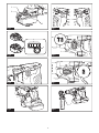
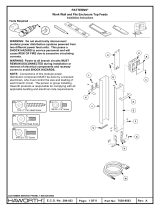
To install the battery cartridge, align the tongue on the
battery cartridge with the groove in the housing and slip
it into place. Insert it all the way until it locks in place
with alittle click. If you can see the red indicator as
shown in the gure, it is not locked completely.
To remove the battery cartridge, slide it from the tool
w h i l e s l i d i n g t h e b u t t o n o n t h e f r o n t o f t h e c a r t r i d g e .
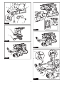
Fig.1: 1. R e d i n d i c a t o r 2. B u t t o n 3. Battery cartridge
CAUTION: Alw ays install the battery cartridge
fully until the red indicator cannot be seen. If n o t ,
it may accidentally fall out of the tool, causing injury to
you or someone around you.
CAUTION: Do not install the battery cartridge
forcibly. If the cartridge does not slide in easily, it is
not being inserted correctly.
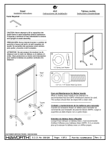
Indicating the remaining battery
capacity
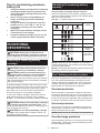
Only for battery cartridges with the indicator
Press the check button on the battery cartridge to indi-
cate the remaining battery capacity. The indicator lamps
l i g h t u p f o r a f e w s e c o n d s .
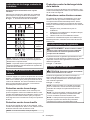
Fig.2: 1. In d i c a t o r l a m p s 2. C h e c k b u t t o n
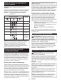
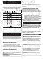
Indicator lamps Remaining
capacity
Lighted O Blinking
75% t o 100%
50% t o 75%
25% t o 50%
0% t o 25%
C h a r g e t h e
battery.
The battery
may have
m a l f u n c t i o n e d .
NOTE: De p e n d i n g o n t h e c o n d i t i o n s o f u s e a n d t h e
ambient temperature, the indication may dier slightly
from the actual capacity.
NOTE: The rst (far left) indicator lamp will blink when
the battery protection system works.
Tool / battery protection system
The tool is equipped with atool/battery protection sys-
tem. This system automatically cuts o power to the
motor to extend tool and battery life. The tool will auto-
matically stop during operation if the tool or battery is
placed under one of the follow ing conditions:
Overload protection
When the battery is operated in amanner that causes
it to draw an abnormally high current, the tool automat-
ically stops without any indication. In this situation, turn
the tool o and stop the application that caused the tool
t o b e c o m e o v e r l o a d e d . T h e n t u r n t h e t o o l o n t o r e s t a r t .
Overheat protection
When the tool or battery is overheated, the tool stops
automatically. In this case, let the tool and battery cool
b e f o r e t u r n i n g t h e t o o l o n a g a i n .
NOTE: W h e n t h e t o o l i s o v e r h e a t e d , t h e l a m p b l i n k s .
Overdischarge protection
When the battery capacity is not enough, the tool stops
automatically. In this case, remove the battery from the
tool and charge the battery.

12 ENGLISH
Protections against other causes
Protection system is also designed for other causes that could
damage the tool and allows the tool to stop automatically.
T a k e a l l t h e f o l l o w i n g s t e p s t o c l e a r t h e c a u s e s , w h e n t h e t o o l
has been brought to atemporary halt or stop in operation.
1.
Turn the tool o, and then turn it on again to restart.
. Charge the battery(ies) or replace it/them with
recharged battery(ies).
. Let the tool and battery(ies) cool down.
If no improvement can be found by restoring protection
system, then contact your local Makita Service Center.
Sw itch action
WARNING: Before installing the battery car-
tridge into the tool, alw ays check to see that the
sw itch trigger actuates properly and returns to
the " OFF" position w hen released.
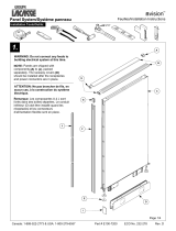
To start the tool, simply pull the switch trigger. Tool
speed is increased by increasing pressure on the switch
t r i g g e r . R e l e a s e t h e s w i t c h t r i g g e r t o s t o p .
Fig.3: 1. S w i t c h t r i g g e r
Lighting up the front lamp
CAUTION: Do not look in the light or see the
source of light directly.
P u l l t h e s w i t c h t r i g g e r t o l i g h t u p t h e l a m p . T h e l a m p
k e e p s o n l i g h t i n g w h i l e t h e s w i t c h t r i g g e r i s b e i n g p u l l e d .
The lamp goes out approximately 1 seconds after
r e l e a s i n g t h e s w i t c h t r i g g e r .
Fig.4: 1. L a m p
NOTE: Use adry cloth to wipe the dirt o the lens of
t h e l a m p . B e c a r e f u l n o t t o s c r a t c h t h e l e n s o f l a m p , o r
it may lower the illumination.
NOTE:
When the tool is overheated, the lamp ashes.
In t h i s c a s e , r e l e a s e t h e s w i t c h t r i g g e r a n d t h e n c o o l
down the tool/battery before operating again.
NOTE:
T h e f r o n t l a m p c a n n o t b e u s e d w h i l e t h e d u s t c o l -
lection system (optional accessory) is installed in the tool.
Reversing sw itch action
CAUTION: Alw ays check the direction of
rotation before operation.
CAUTION: Use the reversing sw itch only after
the tool comes to a complete stop. C h a n g i n g t h e
direction of rotation before the tool stops may dam-
age the tool.
CAUTION: W hen not operating the tool,
alw ays set the reversing sw itch lever to the neu-
tral position.
T h i s t o o l h a s a r e v e r s i n g s w i t c h t o c h a n g e t h e d i r e c t i o n
o f r o t a t i o n . De p r e s s t h e r e v e r s i n g s w i t c h l e v e r f r o m t h e
A s i d e f o r c l o c k w i s e r o t a t i o n o r f r o m t h e B s i d e f o r c o u n -
t e r c l o c k w i s e r o t a t i o n .
W h e n t h e r e v e r s i n g s w i t c h l e v e r i s i n t h e n e u t r a l p o s i -
t i o n , t h e s w i t c h t r i g g e r c a n n o t b e p u l l e d .
Fig.5: 1. R e v e r s i n g s w i t c h l e v e r
Selecting the action mode
NOTICE: Do not rotate the action mode chang-
ing knob w hen the tool is running. T h e t o o l w i l l b e
dam aged.
NOTICE: To avoid rapid w ear on the mode
change mechanism, be sure that the action mode
changing knob is alw ays positively located in one
of the action mode positions.
Rotation w ith hammering
For drilling in concrete, masonry, etc., rotate the action mode
c h a n g i n g k n o b t o t h e symbol. Use acarbide-tipped drill bit.
Fig.6: 1. Ac t i o n m o d e c h a n g i n g k n o b
Rotation only
F o r d r i l l i n g i n w o o d , m e t a l o r p l a s t i c m a t e r i a l s , r o t a t e t h e a c t i o n m o d e
changing knob to the symbol. Use atwist drill bit or wood drill bit.
Fig.7: 1. Ac t i o n m o d e c h a n g i n g k n o b
Electronic function
T h e t o o l i s e q u i p p e d w i t h t h e e l e c t r o n i c f u n c t i o n s f o r
easy operation.
•El e c t r i c b r a k e
T h i s t o o l i s e q u i p p e d w i t h a n e l e c t r i c b r a k e . If t h e
tool consistently fails to quickly cease to function
a f t e r t h e s w i t c h t r i g g e r i s r e l e a s e d , h a v e t h e t o o l
s e r v i c e d a t a M a k i t a s e r v i c e c e n t e r .
•C o n s t a n t s p e e d c o n t r o l
T h e s p e e d c o n t r o l f u n c t i o n p r o v i d e s t h e c o n s t a n t
r o t a t i o n s p e e d r e g a r d l e s s o f l o a d c o n d i t i o n s .
ASSEMBLY
CAUTION: Alw ays be sure that the tool is
switched o and the battery cartridge is removed
before carrying out any w ork on the tool.
Side grip (auxiliary handle)
CAUTION: Alw ays use the side grip to ensure
safe operation.
CAUTION: After installing or adjusting the
side grip, make sure that the side grip is rmly
secured w ith the protrusions on the tool are fully
engaged by the grooves on the side grip.
T o i n s t a l l t h e s i d e g r i p , f o l l o w t h e s t e p s b e l o w .
1. L o o s e n t h e t h u m b s c r e w o n t h e s i d e g r i p .
Fig.8: 1. T h u m b s c r e w
2. In s t a l l t h e s i d e g r i p s o t h a t t h e g r o o v e s o n t h e
grip t in the protrusions on the tool while pressing the
t h u m b s c r e w .
Fig.9: 1. T h u m b s c r e w
3. T i g h t e n t h e t h u m b s c r e w t o s e c u r e t h e g r i p . T h e
grip can be xed at desired angle.

13 ENGLISH
Installing or removing drill bit
Grease
Clean the shank end of the bit and apply grease before
i n s t a l l i n g t h e b i t .
C o a t t h e s h a n k e n d o f t h e b i t b e f o r e h a n d w i t h a s m a l l
a m o u n t o f g r e a s e ( a b o u t 0.5 - 1 g ) . T h i s c h u c k l u b r i c a -
t i o n a s s u r e s s m o o t h a c t i o n a n d l o n g e r s e r v i c e l i f e .
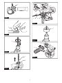
Fig.10: 1. Shank end 2. G r e a s e
In s e r t t h e d r i l l b i t i n t o t h e t o o l . T u r n t h e d r i l l b i t a n d p u s h
i t i n u n t i l i t e n g a g e s .
After installing the drill bit, always make sure that the
drill bit is securely held in place by trying to pull it out.
Fig.11: 1. Dr i l l b i t
T o r e m o v e t h e d r i l l b i t , p u s h t h e c h u c k c o v e r d o w n a l l
the way and pull the drill bit out.
Fig.12: 1. Dr i l l b i t 2. C h u c k c o v e r
Depth gauge
T h e d e p t h g a u g e i s c o n v e n i e n t f o r d r i l l i n g h o l e s o f
u n i f o r m d e p t h .
P r e s s a n d h o l d t h e l o c k b u t t o n , a n d t h e n i n s e r t t h e
d e p t h g a u g e i n t o t h e h o l e . M a k e s u r e t h a t t h e t o o t h e d
s i d e o f t h e d e p t h g a u g e f a c e s t h e m a r k i n g .
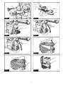
Fig.13: 1. Depth gauge 2. L o c k b u t t o n 3. M a r k i n g
4. T o o t h e d s i d e
Adjust the depth gauge by moving it back and forth
while pressing the lock button. After the adjustment,
r e l e a s e t h e l o c k b u t t o n t o l o c k t h e d e p t h g a u g e .
NOTE: M a k e s u r e t h a t t h e d e p t h g a u g e d o e s n o t
touch the main body of the tool when attaching it.
Dust cup
Optional accessory
U s e t h e d u s t c u p t o p r e v e n t d u s t f r o m f a l l i n g o v e r t h e
tool and on yourself when performing overhead drilling
o p e r a t i o n s . At t a c h t h e d u s t c u p t o t h e b i t a s s h o w n i n
the gure. The size of bits which the dust cup can be
a t t a c h e d t o i s a s f o l l o w s .
M odel B i t d i a m e t e r
Du s t c u p 5 6 m m - 14 .5 m m
Du s t c u p 9 12 m m - 16 m m
Fig.14: 1. Du s t c u p
Dust cup set
Optional accessory
Installing the dust cup set
NOTICE: Do not use the dust cup set w hen drill-
ing in metal or similar. It may damage the dust cup
set due to the heat produced by small metal dust or
s i m i l a r . Do n o t i n s t a l l o r r e m o v e t h e d u s t c u p s e t w i t h
the drill bit installed in the tool. It may damage the
d u s t c u p s e t a n d c a u s e d u s t l e a k .
B e f o r e i n s t a l l i n g t h e d u s t c u p s e t , r e m o v e t h e d r i l l b i t
f r o m t h e t o o l i f i n s t a l l e d .
1. L o o s e n t h e t h u m b s c r e w o n t h e s i d e g r i p .
2. In s t a l l t h e d u s t c u p s e t s o t h a t t h e c l a w s o f t h e
dust cup t in the slits on the side grip.
Fig.15: 1. Du s t c u p s e t 2. S i d e g r i p
3. In s t a l l t h e s i d e g r i p s o t h a t t h e g r o o v e o n t h e g r i p
t in the protrusion on the tool. Tighten the thumb screw
t o s e c u r e t h e s i d e g r i p .
Fig.16: 1. S i d e g r i p 2. G r o o v e 3. P r o t r u s i o n
NOTE: If you connect avacuum cleaner to the dust
c u p s e t , r e m o v e t h e d u s t c a p b e f o r e c o n n e c t i n g i t .
Fig.17: 1. Du s t c a p
Removing the drill bit
T o r e m o v e t h e d r i l l b i t , p u l l t h e c h u c k c o v e r d o w n a l l t h e
way and pull the drill bit out.
Fig.18: 1. Dr i l l b i t 2. C h u c k c o v e r
Removing the dust cup set
T o r e m o v e t h e d u s t c u p s e t , f o l l o w t h e s t e p s b e l o w .
1. L o o s e n t h e t h u m b s c r e w o n t h e s i d e g r i p . R e m o v e
t h e s i d e g r i p f r o m t h e t o o l .
Fig.19: 1. T h u m b s c r e w
2. H o l d t h e r o o t o f d u s t c u p a n d p u l l i t o u t .
NOTE: If it is dicult to remove the dust cup set,
remove the claws of the dust cup one by one by
s w i n g i n g a n d p u l l i n g t h e r o o t o f t h e d u s t c u p .
Fig.20: 1. Du s t c u p
NOTE: If the cap comes o from the dust cup set,
p l a c e i t b a c k t o t h e o r i g i n a l p o s i t i o n .
T o p l a c e t h e c a p b a c k t o t h e o r i g i n a l p o s i t i o n , f o l l o w t h e
s t e p s b e l o w .
1. T u r n t h e b e l l o w s c o u n t e r c l o c k w i s e a n d r e m o v e i t
f r o m t h e d u s t c u p s e t a t t a c h m e n t u n i t w h i l e t h e b e l l o w s
i s u n l o c k e d .
Fig.21: 1. B e l l o w s 2. At t a c h m e n t u n i t
2. S e t t h e c a p b a c k i n p l a c e w i t h i t s l e t t e r e d s i d e
f a c i n g u p w a r d s .
Fig.22: 1. C a p 2. At t a c h m e n t u n i t
3. Be sure that the grooves around the cap well t in
t h e l i p s o f t h e u p p e r o p e n i n g o f t h e a t t a c h m e n t u n i t .

14 ENGLISH
Tool hanger
Optional accessory
CAUTION: Do not use damaged tool hanger
and screw . Before use, alw ays check for dam-
ages, cracks or deformations, and make sure that
the screw is tightened.
CAUTION: Install or remove the tool hanger
on a stable table or surface. Be sure to use the
screw provided w ith the tool hanger only. After
installing the tool hanger, make sure that the tool
hanger is securely installed w ith the screw .
CAUTION: Do not remove the battery car-
tridge w hile hanging the tool. The tool may fall if the
s c r e w i s n o t t i g h t e n e d .
The tool hanger is intended for connecting the lanyard
( t e t h e r s t r a p ) .
B e f o r e i n s t a l l i n g t h e t o o l h a n g e r , r e m o v e t h e r u b b e r c a p
f r o m t h e s c r e w h o l e i n t h e m o u n t i n g b r a c k e t . In s e r t t h e
s q u a r e n u t u n d e r t h e b r a c k e t . T i g h t e n t h e t o o l h a n g e r
w i t h s c r e w i n p l a c e .
Fig.23: 1. R ubber cap 2. M o u n t i n g b r a c k e t
3. Square nut 4. Tool hanger 5. S c r e w
Safety w arnings about connecting
lanyard (tether strap) to the tool
hanger
Safety warnings specic for use at height
Read all safety w arnings and instructions. F a i l u r e
to follow the warnings and instructions may result in
serious injury.
1. Alw ays keep the tool tethered w hen w orking
" at height" . Maximum lanyard length is 2 m.
The maximum permissible fall height for lan-
yard (tether strap) must not exceed 2 m.
2. Use only w ith lanyards appropriate for this tool
type and rated for at least 6.0 kg.
3. Do not anchor the tool lanyard to anything on
your body or on movable components. Anchor
the tool lanyard to a rigid structure that can
w ithstand the forces of a dropped tool.
4 . Make sure the lanyard is properly secured at
each end prior to use.
5. Inspect the tool and lanyard before each use
for damage and proper function (including
fabric and stitching). Do not use if damaged or
not functioning properly.
6 . Do not w rap lanyards around or allow them to
come in contact w ith sharp or rough edges.
7. Fasten the other end of the lanyard outside
the w orking area so that a falling tool is held
securely.
8. Attach the lanyard so that the tool w ill move
aw ay from the operator if it falls. Dr o p p e d t o o l s
will swing on the lanyard, which could cause injury
o r l o s s o f b a l a n c e .
9 . Do not use near moving parts or running
machinery. Failure to do so may result in acrush
or entanglem ent hazard.
10. Do not carry the tool by the attachment device
or the lanyard.
11. Only transfer the tool betw een your hands
w hile you are properly balanced.
12. Do not attach lanyards to the tool in a w ay that
keeps sw itches or trigger-lock (if supplied)
from operating properly.
13. Avoid getting tangled in the lanyard.
14 . Keep lanyard aw ay from the drilling area of the
tool.
15. Use a locking carabiner (multi-action and
screw gate type). Do not use single action
spring clip carabiners.
16 . In the event the tool is dropped, it must be
tagged and removed from service, and should
be inspected by a Makita Factory or Authorized
Service Center.
17. Do not hang the tool on your w aist. H e a t e d t o o l
and its accessory may touch your skin and burn
injury result.
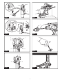
Fig.24: 1. Tool hanger 2. Lanyard (tether strap)
DUST COLLECTION
SYSTEM
Optional accessory
The dust collection system is designed to collect dusts
eectively when the concrete drilling operation.
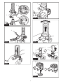
Fig.25: 1. Dust collection system
CAUTION: The dust collection system is
intended for drilling in concrete only. Do not use
the dust collection system for drilling in metal or
w ood.
CAUTION: W hen using the tool w ith the dust
collection system, be sure to attach the lter
to the dust collection system to prevent dust
inhalation.
CAUTION: Before using the dust collection
system, check that the lter is not damaged and
the inner pipe is free of dust and foreign matter.
Failure to do so may cause dust inhalation.
CAUTION: The dust collection system col-
lects the generated dust at a considerable rate,
but not all dust can be collected.
NOTICE: Do not use the dust collection system
for core drilling or chiseling.
NOTICE: Do not use the dust collection system
for metal or w ood. The dust collection system is
intended for concrete only.
NOTICE: Do not use the dust collection system
for drilling in w et concrete or use this system
in w et environment. Failure to do so may cause
malfunction.

15 ENGLISH
Installing or removing
NOTICE: Before installing the dust collection
system, clean the joint parts of the tool and the
dust collection system. Foreign matters on the joint
parts may cause it dicult to install the dust collection
system. If any dust remains on the air duct, the dust
comes into the tool and causes jam in the airow or
b r e a k a g e o f t h e t o o l .
To install the dust collection system, insert the tool
completely into the dust collection system until the tool
i s l o c k e d i n p l a c e w i t h a l i t t l e c l i c k .
Fig.26
To remove the dust collection system, pull up the tool
while pressing the lock-o button.
Fig.27: 1. Lock-o button
Adjusting nozzle position
CAUTION: Do not point the nozzle at yourself
or others w hen releasing the nozzle by pushing
the guide adjustment button.
S l i d e i n a n d o u t t h e n o z z l e g u i d e w h i l e p r e s s i n g t h e
guide adjustment button, and then release the button
at an exact position where the tip of the drill bit sits just
b e h i n d t h e f r o n t s u r f a c e o f t h e n o z z l e .
Fig.28: 1. N o z z l e g u i d e 2. Guide adjustment button
3. T i p o f d r i l l b i t 4. F r o n t s u r f a c e o f n o z z l e
Adjusting drilling depths
Drilling depths can be adjusted by changing the lengths
between the depth adjustment button and the support
arm for nozzle guide. Press and hold the depth adjust-
ment button and slide it to your desired position.
Fig.29: 1. Depth adjustment button 2. N o z z l e g u i d e
3. S u p p o r t a r m f o r n o z z l e g u i d e 4. Dr i l l i n g
depths
Beating dust on the lter
CAUTION: Do not turn the dial on the dust
case w hile the dust case is removed from the
dust collection system. Doing so may cause dust
inhalation.
CAUTION: Always switch o the tool when
turning the dial on the dust case. T u r n i n g t h e d i a l
while the tool is running may result in the loss of
c o n t r o l o f t h e t o o l .
By beating the dust on the lter inside the dust case,
you can keep the vacuum eciency and also reduce
t h e n u m b e r o f t i m e s t o d i s p o s e o f t h e d u s t .
T u r n t h e d i a l o n t h e d u s t c a s e t h r e e t i m e s a f t e r c o l -
lecting every 5, mm3of dust or when you feel the
v a c u u m p e r f o r m a n c e d e c l i n e d .
NOTE: 50, 000 m m 3 o f d u s t e q u i v a l e n t s t o d r i l l i n g 10
h o l e s o f ø 10 m m a n d 6 5 m m d e p t h .
Fig.30: 1. Du s t c a s e 2. Di a l
Disposing of dust
CAUTION: Alw ays be sure that the tool is
switched o and the battery cartridge is removed
before carrying out any w ork on the tool.
CAUTION: Be sure to w ear dust mask w hen
disposing of dust.
CAUTION: Be sure that the tool is completely
stopped w hen disposing of dust.
CAUTION: Empty the dust case regularly
before the dust case becomes full. F a i l u r e t o d o s o
may decrease the dust collection performance and
c a u s e d u s t i n h a l a t i o n .
CAUTION: The performance of dust collection
decreases if the lter in the dust case become
clogged. Replace the lter with new one after
approximately 200 times of dust fulllment as a
guide. Failure to do so may cause dust inhalation.
1. R e m o v e t h e d u s t c a s e w h i l e p r e s s i n g d o w n t h e
l e v e r o f t h e d u s t c a s e .
Fig.31: 1. Lever
2. O p e n t h e c o v e r o f t h e d u s t c a s e .
Fig.32: 1. C o v e r
3. Dispose of the dust, and then clean the lter.
Fig.33
NOTICE: hen cleaning the lter, tap the case
of the lter gently by hand to remove dust. Do not
tap the lter directly touch the lter with brush
or similar or blow compressed air on the lter.
Doing so may damage the lter.
Replacing lter of dust case
1. R e m o v e t h e d u s t c a s e w h i l e p r e s s i n g d o w n t h e
l e v e r o f t h e d u s t c a s e .
Fig.34: 1. Lever
2. Open the lter cover of the dust case.
Fig.35: 1. F i l t e r c o v e r
3. Remove the lter from the lter case.
Fig.36: 1. F i l t e r 2. F i l t e r c a s e
4. Attach anew lter to the lter case, and then
attach the lter cover.
5. C l o s e t h e c o v e r o f t h e d u s t c a s e , a n d t h e n a t t a c h
the dust case to the dust collection system.
Replacing sealing cap
1.
Insert aat-blade screwdriver into one of the grooves
placed on the sides of the nozzle head. Tilt the at-blade
s c r e w d r i v e r a t a n a n g l e t o s q u e e z e a n d p o p t h e c u b e h o o k
o f t h e s e a l i n g c a p o u t . T h e n p e e l t h e r u b b e r e d g e o f t h e
sealing cap away from the rim of the nozzle head opening.
Fig.37:
1. S e a l i n g c a p 2. C ube hook 3. G r o o v e 4. N o z z l e h e a d
2. S e t o n e o f c u b e h o o k s o f a n e w s e a l i n g c a p i n t o
t h e l o w e r p a r t o f t h e g r o o v e i n t h e n o z z l e h e a d w i t h a
r e c e s s e d s u r f a c e o f t h e s e a l i n g c a p f a c i n g f o r w a r d .
Fig.38: 1. C ube hooks 2. L o w e r p a r t o f t h e g r o o v e
3. S e a l i n g c a p 4. R e c e s s e d s u r f a c e

16 ENGLISH
3.
P l a c e t h e o t h e r h o o k i n t o t h e o p p o s i t e s i d e , w h i l e
repositioning the sealing cap to t nely to the nozzle head.
Fig.39: 1. S e a l i n g c a p 2. C ube hook 3. L o w e r p a r t
o f t h e g r o o v e 4. N o z z l e h e a d 5. R i m s
4. Gently lay the rubber edge of the sealing cap
d o w n o v e r t h e r i m o f t h e n o z z l e h e a d o p e n i n g f r o m
b o t t o m t o t o p .
Fig.40:
1. R ubber edge 2. S e a l i n g c a p 3. N o z z l e h e a d
OPERATION
CAUTION: Alw ays use the side grip (auxiliary
handle and rmly hold the tool by both side grip
and sw itch handle during operations.
CAUTION: Alw ays make sure that the w ork-
piece is secured before operation.
CAUTION: Do not pull the tool out forcibly
even the bit gets stuck. Loss of control may
cause injury.
NOTICE: Before using the dust collection sys-
tem w ith the tool, read the section about the dust
collection system.
NOTE: If the battery cartridge is in low temperature,
the tool’s capability may not be fully obtained. In this
case, warm up the battery cartridge by using the
tool with no load for awhile to fully obtain the tool’s
capability.
Fig.41
Hammer drilling operation
CAUTION: T h e r e i s t r e m e n d o u s a n d s u d d e n
t w i s t i n g f o r c e e x e r t e d o n t h e t o o l / d r i l l b i t a t t h e t i m e o f
h o l e b r e a k -t h r o u g h , w h e n t h e h o l e b e c o m e s c l o g g e d
w i t h c h i p s a n d p a r t i c l e s , o r w h e n s t r i k i n g r e i n f o r c i n g
r o d s e m b e d d e d i n t h e c o n c r e t e . Alw ays use the side
grip auxiliary handle and rmly hold the tool by
both side grip and sw itch handle during opera-
tions. Failure to do so may result in the loss of control
of the tool and potentially severe injury.
S e t t h e a c t i o n m o d e c h a n g i n g k n o b t o t h e symbol.
P o s i t i o n t h e d r i l l b i t a t t h e d e s i r e d l o c a t i o n f o r t h e h o l e ,
t h e n p u l l t h e s w i t c h t r i g g e r .
Apply feed force to the switch handle (main handle) for
working accuracy and eciency, and hold the side grip
(auxiliary handle) to keep balance of the tool.
Keep the tool in position and prevent it from slipping
away from the hole.
Do not apply more pressure when the hole becomes
c l o g g e d w i t h c h i p s o r p a r t i c l e s . In s t e a d , r u n t h e t o o l a t
an idle, then remove the drill bit partially from the hole.
By repeating this several times, the hole will be cleaned
out and normal drilling may be resumed.
NOTE: Eccentricity in the drill bit rotation may occur
w h i l e o p e r a t i n g t h e t o o l w i t h n o l o a d . T h e t o o l a u t o -
matically centers itself during operation. This does not
aect the drilling precision.
Drilling in w ood or metal
CAUTION: Hold the tool rmly and exert care
w hen the drill bit begins to break through the
w orkpiece. T h e r e i s a t r e m e n d o u s f o r c e e x e r t e d o n
t h e t o o l / d r i l l b i t a t t h e t i m e o f h o l e b r e a k t h r o u g h .
CAUTION: A stuck drill bit can be removed
simply by setting the reversing sw itch to reverse
rotation in order to back out. How ever, the tool
may back out abruptly if you do not hold it rmly.
CAUTION: Alw ays secure w orkpieces in a
vise or similar hold-dow n device.
NOTICE: Never use “ rotation w ith hammering”
w hen the drill chuck is installed on the tool. T h e
drill chuck may be damaged.
Also, the drill chuck will come o when reversing the
t o o l .
NOTICE: Pressing excessively on the tool w ill
not speed up the drilling. In f a c t , t h i s e x c e s s i v e
pressure will only serve to damage the tip of your drill
b i t , d e c r e a s e t h e t o o l p e r f o r m a n c e a n d s h o r t e n t h e
s e r v i c e l i f e o f t h e t o o l .
S e t t h e a c t i o n m o d e c h a n g i n g k n o b t o t h e symbol.
Attach the chuck adapter to akeyless drill chuck to
w h i c h 1/ 2" -20 s i z e s c r e w c a n b e i n s t a l l e d , a n d t h e n
i n s t a l l t h e m t o t h e t o o l . W h e n i n s t a l l i n g i t , r e f e r t o t h e
s e c t i o n “ In s t a l l i n g o r r e m o v i n g d r i l l b i t ” .
Fig.42: 1. Drill chuck assembly 2. C huck adapter
Blow -out bulb
Optional accessory
Af t e r d r i l l i n g t h e h o l e , u s e t h e b l o w -o u t b u l b t o c l e a n t h e
d u s t o u t o f t h e h o l e .
Fig.43
Using dust cup set
Optional accessory
F i t t h e d u s t c u p s e t a g a i n s t t h e c e i l i n g w h e n o p e r a t i n g
t h e t o o l .
Fig.44
NOTICE: Do not use the dust cup set w hen drill-
ing in metal or similar. It may damage the dust
cup set due to the heat produced by small metal
dust or similar.
NOTICE: Do not install or remove the dust cup
set w ith the drill bit installed in the tool. It may
damage the dust cup set and cause dust leak.

17 ENGLISH
MAINTENANCE
CAUTION: Alw ays be sure that the tool is
switched o and the battery cartridge is removed
before attempting to perform inspection or
maintenance.
NOTICE: Never use gasoline, benzine, thinner,
alcohol or the like. Discoloration, deformation or
cracks may result.
T o m a i n t a i n p r o d u c t S AF ET Y a n d R EL IAB IL IT Y ,
repairs, any other maintenance or adjustment should
be performed by Makita Authorized or Factory Service
Centers, always using Makita replacement parts.
OPTIONAL
ACCESSORIES
CAUTION: These accessories or attachments
are recommended for use w ith your Makita tool
specied in this manual. The use of any other
a c c e s s o r i e s o r a t t a c h m e n t s m i g h t p r e s e n t a r i s k o f
injury to persons. Only use accessory or attachment
f o r i t s s t a t e d p u r p o s e .
If you need any assistance for more details regard-
ing these accessories, ask your local Makita Service
C e n t e r .
•C a r b i d e -t i p p e d d r i l l b i t s ( S DS -P l u s c a r b i d e -t i p p e d
b i t s )
•C huck adapter
Keyless drill chuck
•B i t g r e a s e
•Depth gauge
•B l o w -o u t b u l b
•Du s t c u p
•Du s t c u p s e t
Dust collection system
•Tool hanger
Makita genuine battery and charger
NOTE: Some items in the list may be included in the
tool package as standard accessories. They may
dier from country to country.

18 FRANÇAIS
FRANÇAIS (Instructions originales)
SPÉ CIFICATIONS
Modè le :DHR183
C a p a c i t é s d e p e r ç a g e B é t o n 18 m m
Ac i e r 13 m m
B o i s 24 m m
V i t e s s e à v i d e 0 - 1 100 m i n -1
F r a p p e s p a r m i n u t e 0 - 5 000 m i n -1
L o n g u e u r t o t a l e ( a v e c B L 186 0B ) 288 m m
T e n s i o n n o m i n a l e 18 V C C
P o i d s n e t 2, 1 - 2, 9 k g
Accessoire en option
Modè le :DX 16
P e r f o r m a n c e d ’ a s p i r a t i o n 0, 24 l / m i n
C o u r s e d e t r a v a i l J u s q u ’ à 105 m m
F o r e t a d é q u a t J u s q u ’ à 16 5 m m
P o i d s n e t 0, 77 k g
tant donné l’évolution constante de notre programme de recherche et de développement, les spécications
contenues dans ce manuel sont sujettes àmodication sans préavis.
Les spécications peuvent varier suivant les pays.
Le poids peut tre diérent selon les accessoires, notamment la batterie. Les associations la plus légère et la
p l u s l o u r d e , c o n f o r m é m e n t à l a p r o c é d u r e EP T A 01/ 2014 , s o n t i n d i q u é e s d a n s l e t a b l e a u .
Batterie et chargeur applicables
B a t t e r i e B L 1815N / B L 1820B / B L 1830B / B L 184 0B / B L 1850B / B L 186 0B
C hargeur DC 18R C / DC 18R D / DC 18R E / DC 18S D / DC 18S E / DC 18S F /
DC 18S H / DC 18W C
•C e r t a i n s c h a r g e u r s e t b a t t e r i e s r é p e r t o r i é s c i -d e s s u s p e u v e n t n e p a s ê t r e d i s p o n i b l e s s e l o n l a r é g i o n o ù v o u s
r é s i d e z .
AVERTISSEMENT : N’ utilisez que les batteries et les chargeurs répertoriés ci-dessus. L ’ u t i l i s a t i o n
d ’ a u t r e s b a t t e r i e s e t c h a r g e u r s p e u t p r o v o q u e r d e s b l e s s u r e s e t / o u u n i n c e n d i e .
Source d’ alimentation connectée par cordon recommandée
S u p p o r t d ’ a l i m e n t a t i o n p o r t a b l e P DC 01
•L a o u l e s s o u r c e s d ’ a l i m e n t a t i o n c o n n e c t é e s p a r c o r d o n r é p e r t o r i é e s c i -d e s s u s p e u v e n t n e p a s ê t r e d i s p o -
n i b l e s s e l o n l a r é g i o n o ù v o u s r é s i d e z .
•Av a n t d ’ u t i l i s e r l a s o u r c e d ’ a l i m e n t a t i o n c o n n e c t é e p a r c o r d o n , l i s e z l e s i n s t r u c t i o n s e t l e s a v e r t i s s e m e n t s
i n s c r i t s d e s s u s .
Utilisation prévue
L ’ o u t i l e s t c o n ç u p o u r l e p e r ç a g e a v e c m a r t e l a g e e t l e
p e r ç a g e d a n s l a b r i q u e , l e b é t o n e t l a p i e r r e .
Il c o n v i e n t é g a l e m e n t a u p e r ç a g e s a n s i m p a c t d a n s l e
b o i s , l e m é t a l , l a c é r a m i q u e e t l e p l a s t i q u e .
Bruit
Niveau de bruit pondéré Atypique, déterminé selon
EN 6 284 1-2-6 :
Modè le DHR183
N i v e a u d e p r e s s i o n s o n o r e ( L p A): 9 0 d B ( A)
N i v e a u d e p u i s s a n c e s o n o r e ( L W A) : 101 d B ( A)
Incertitude (K) :dB (A)
Modè le DHR183 avec DX 16
N i v e a u d e p r e s s i o n s o n o r e ( L p A): 9 0 d B ( A)
N i v e a u d e p u i s s a n c e s o n o r e ( L W A) : 101 d B ( A)
Incertitude (K) :dB (A)

19 FRANÇAIS
NOTE : L a o u l e s v a l e u r s d ’ é m i s s i o n d e b r u i t d é c l a -
r é e s o n t é t é m e s u r é e s c o n f o r m é m e n t à l a m é t h o d e
d e t e s t s t a n d a r d e t p e u v e n t ê t r e u t i l i s é e s p o u r c o m -
p a r e r l e s o u t i l s e n t r e e u x .
NOTE : L a o u l e s v a l e u r s d ’ é m i s s i o n d e b r u i t d é c l a -
r é e s p e u v e n t a u s s i ê t r e u t i l i s é e s p o u r l ’ é v a l u a t i o n
p r é l i m i n a i r e d e l ’ e x p o s i t i o n .
AVERTISSEMENT : Portez un serre-tê te
antibruit.
AVERTISSEMENT : L’ émission de bruit
lors de l’ usage réel de l’ outil électrique peut ê tre
diérente de la ou des valeurs déclarées, suivant
la façon dont l’ outil est utilisé, particuliè rement
selon le type de piè ce usinée.
AVERTISSEMENT : Les mesures de sécurité
à prendre pour protéger l’ utilisateur doivent ê tre
basées sur une estimation de l’ exposition dans
des conditions réelles d’ utilisation (en tenant
compte de toutes les composantes du cycle
d’ utilisation, comme par exemple le moment de
sa mise hors tension, lorsqu’ il tourne à vide et le
moment de son déclenchement).
Vibrations
L e t a b l e a u s u i v a n t i n d i q u e l a v a l e u r t o t a l e d e v i b r a t i o n s
( s o m m e d e v e c t e u r t r i a x i a l ) d é t e r m i n é e s e l o n l a n o r m e
applicable.
Mode de
travail
É mission de
vibrations
Incertitude (K)
Norme
applicable/
Condition de
test
P e r ç a g e a v e c
m a r t e l a g e
d a n s l e b é t o n
( a h , H D)
7, 5 m / s 21, 5 m / s 2EN 6 284 1-2-6
7, 5 m / s 21, 5 m / s 2O p é r a t i o n
p r a t i q u e
r e c o m m a n -
dée*
P e r ç a g e a v e c
m a r t e l a g e
d a n s l e b é t o n
a v e c l e DX 16
( a h , H D)
7, 6 m / s 21, 7 m / s 2EN 6 284 1-2-6
7, 7 m / s 21, 5 m / s 2O p é r a t i o n
p r a t i q u e
r e c o m m a n -
dée*
* L a c o n d i t i o n d e t e s t d e l ’ o p é r a t i o n p r a t i q u e r e c o m -
m a n d é e s a t i s f a i t l a n o r m e EN 6 284 1-2-6 , à l ’ e x c e p t i o n
d e s p o i n t s s u i v a n t s :
•La force d’avance est appliquée à la poignée
p i s t o l e t ( p o i g n é e p r i n c i p a l e ) p o u r u n e p r é c i s i o n e t
une ecacité du travail.
•La poignée latérale/poignée de côté (poignée
a u x i l i a i r e ) e s t t e n u e p o u r m a i n t e n i r l ’ é q u i l i b r e d e
l ’ o u t i l .
NOTE : L a o u l e s v a l e u r s d e v i b r a t i o n t o t a l e s d é c l a -
r é e s o n t é t é m e s u r é e s c o n f o r m é m e n t à l a m é t h o d e
d e t e s t s t a n d a r d e t p e u v e n t ê t r e u t i l i s é e s p o u r c o m -
p a r e r l e s o u t i l s e n t r e e u x .
NOTE : L a o u l e s v a l e u r s d e v i b r a t i o n t o t a l e s d é c l a -
r é e s p e u v e n t a u s s i ê t r e u t i l i s é e s p o u r l ’ é v a l u a t i o n
p r é l i m i n a i r e d e l ’ e x p o s i t i o n .
AVERTISSEMENT : L’ émission de vibrations
lors de l’ usage réel de l’ outil électrique peut ê tre
diérente de la ou des valeurs déclarées, suivant
la façon dont l’ outil est utilisé, particuliè rement
selon le type de piè ce usinée.
AVERTISSEMENT : Les mesures de sécurité
à prendre pour protéger l’ utilisateur doivent ê tre
basées sur une estimation de l’ exposition dans
des conditions réelles d’ utilisation (en tenant
compte de toutes les composantes du cycle
d’ utilisation, comme par exemple le moment de
sa mise hors tension, lorsqu’ il tourne à vide et le
moment de son déclenchement).
Déclarations de conformité
Pour les pays européens uniquement
L e s d é c l a r a t i o n s d e c o n f o r m i t é s o n t f o u r n i e s e n An n e x e
A à c e m o d e d ’ e m p l o i .
CONSIGNES DE
SÉ CURITÉ
Consignes de sécurité générales
pour outils électriques
AVERTISSEMENT Veuillez lire toutes les
consignes de sécurité, instructions, illustrations
et spécications ui accompagnent cet outil élec-
trique. L e n o n -r e s p e c t d e t o u t e s l e s i n s t r u c t i o n s i n d i -
q u é e s c i -d e s s o u s p e u t e n t r a î n e r u n e é l e c t r o c u t i o n , u n
i n c e n d i e e t / o u d e g r a v e s b l e s s u r e s .
Conservez toutes les mises en
garde et instructions pour réfé-
rence ultérieure.
L e t e r m e « o u t i l é l e c t r i q u e » d a n s l e s a v e r t i s s e m e n t s
f a i t r é f é r e n c e à l ’ o u t i l é l e c t r i q u e a l i m e n t é p a r l e s e c t e u r
( a v e c c o r d o n d ’ a l i m e n t a t i o n ) o u à l ’ o u t i l é l e c t r i q u e f o n c -
t i o n n a n t s u r b a t t e r i e ( s a n s c o r d o n d ’ a l i m e n t a t i o n ) .
CONSIGNES DE SÉ CURITÉ POUR
PERFORATEUR SANS FIL
Consignes de sécurité pour toutes les tâ ches
1. Portez des protecteurs d’ oreilles. L ’ e x p o s i t i o n
a u b r u i t p e u t e n t r a î n e r l a s u r d i t é .
2. Utilisez la ou les poignées auxiliaires, si l’ outil
en possè de. T o u t e p e r t e d e m a î t r i s e d e l ’ o u t i l
c o m p o r t e u n r i s q u e d e b l e s s u r e .
3. Tenez l’ outil électrique par des surfaces de
prise isolées lorsue vous eectuez une tche
au cours de laquelle l’ accessoire de coupe
peut entrer en contact avec des ls cachés.
Le contact de l’accessoire de coupe avec un l
s o u s t e n s i o n p e u t t r a n s m e t t r e d u c o u r a n t d a n s l e s
pièces métalliques exposées de l’outil électrique
e t é l e c t r o c u t e r l ’ o p é r a t e u r .

20 FRANÇAIS
Consignes de sécurité en cas d’ utilisation de forets
longs avec un marteau perforateur
1.
Commencez toujours le perçage à basse vitesse
avec la pointe du foret en contact avec la piè ce. À
u n e v i t e s s e p l u s é l e v é e , l e f o r e t r i s q u e d e s e t o r d r e
s ’ i l l u i e s t p e r m i s d e t o u r n e r l i b r e m e n t s a n s t o u c h e r l a
pièce, ce qui présente un risque de blessure.
2. Appliquez une pression uniquement en ligne
directe avec le foret et n’ exercez pas une pres-
sion excessive. L e s f o r e t s p e u v e n t s e t o r d r e e t
s e c a s s e r o u p r o v o q u e r l a p e r t e d e c o n t r ô l e , c e
q u i p r é s e n t e u n r i s q u e d e b l e s s u r e .
Consignes de sécurité supplémentaires
1.
Portez un casque de sécurité (casque de chan-
tier), des lunettes de sécurité et/ou un écran
facial. Les lunettes de vue ou les lunettes de
soleil NE sont PAS des lunettes de sécurité. Il est
également vivement recommandé de porter un
masque anti-poussiè re et des gants matelassés.
2. Avant utilisation, assurez-vous que le foret est
bien xé en place.
3. Dans des conditions normales de fonctionne-
ment, l’ outil est conçu pour émettre des vibra-
tions. Les vis peuvent se desserrer facilement
et provoquer une panne ou un accident. Avant
utilisation, vériez soigneusement ue les vis
sont bien serrées.
4 . Par temps froid ou si l’ outil n’ a pas été utilisé
pendant longtemps, laissez-le chauer un
instant en le faisant fonctionner à vide. Cela
ramollira le lubriant. Si vous ne chauez pas
adéquatement l’ outil, le martelage s’ exécutera
dicilement.
5. Assurez-vous toujours de travailler en position
stable. Veillez à ce que personne ne se trouve
en dessous de vous quand vous utilisez l’ outil
en hauteur.
6 . Tenez l’ outil fermement à deux mains.
7. É loignez les mains des piè ces en mouvement.
8. Ne vous éloignez pas en laissant l’ outil tour-
ner. Ne le faites fonctionner que lorsque vous
l’ avez bien en main.
9 . Ne pointez l’ outil vers personne dans la zone
d’ utilisation. Le foret peut ê tre projeté et bles-
ser gravement quelqu’ un.
10. Ne touchez pas le foret, les piè ces proches du
foret ou la piè ce immédiatement aprè s l’ exécu-
tion du travail ; ils peuvent ê tre extrê mement
chauds et vous brû ler la peau.
11. Certains matériaux contiennent des produits
chimiques qui peuvent ê tre toxiques. Prenez
garde de ne pas avaler la poussiè re et évitez
tout contact avec la peau. Suivez les données
de sécurité du fournisseur du matériau.
12. Assurez-vous toujours que l’ outil est hors
tension et que la batterie et le foret sont retirés
avant de passer l’ outil à une autre personne.
13. Avant utilisation, assurez-vous qu’ aucun objet
tel que des conduites électriques, de tuyaux
d’ eau ou de tuyaux de gaz n’ est pas enterré
sous la zone de travail. S i n o n , l e f o r e t / b u r i n
r i s q u e d ’ e n t r e r e n c o n t a c t a v e c e u x , c e q u i p e u t
e n t r a î n e r u n e é l e c t r o c u t i o n , u n e d i s p e r s i o n é l e c -
t r i q u e o u u n e f u i t e d e g a z .
14 . Ne faites pas tourner l’ outil à vide inutilement.
CONSERVEZ CES
INSTRUCTIONS.
AVERTISSEMENT : NE vous laissez PAS
tromper au l dune utilisation répétée par un
sentiment d’ aisance et de familiarité avec le
produit, en négligeant le respect rigoureux des
consignes de sécurité qui accompagnent le pro-
duit en question. La MAUVAISE UTILISATION de
l’ outil ou l’ ignorance des consignes de sécurité
indiquées dans ce mode d’ emploi peut entraî ner
de graves blessures.
Consignes de sécurité importantes
pour la batterie
1. Avant d’ utiliser la batterie, lisez toutes les
instructions et précautions relatives (1) au
chargeur de batterie, (2) à la batterie, et (3) au
produit utilisant la batterie.
2. Ne désassemblez pas et ne modiez pas la
batterie. C e l a p o u r r a i t e n t r a î n e r u n i n c e n d i e , u n e
c h a l e u r e x c e s s i v e o u u n e e x p l o s i o n .
3. Cessez immédiatement l’ utilisation si le temps
de fonctionnement devient excessivement
court. Il y a risue de surchaue, de brlures,
voire d’ explosion.
4 . Si l’ électrolyte pénè tre dans vos yeux, rin-
cez-les à l’ eau claire et consultez immédiate-
ment un médecin. Il y a risque de perte de la
vue.
5. Ne court-circuitez pas la batterie :
( 1) Ne touchez les bornes avec aucun maté-
riau conducteur.
( 2) É vitez de ranger la batterie dans un
conteneur avec d’ autres objets métal-
liques, par exemple des clous, des piè ces
de monnaie, etc.
( 3) N’ exposez pas la batterie à l’ eau ou à la
pluie.
Un court-circuit de la batterie peut provoquer
une intensité de courant élevée, une sur-
chaue, parfois des brlures et mme une
panne.
6 . Ne rangez ni n’ utilisez l’ outil et la batterie dans
un endroit où la température risque d’ atteindre
ou de dépasser 50 ° C.
7. Ne jetez pas la batterie au feu mê me si elle est
sérieusement endommagée ou complè tement
épuisée. La batterie peut exploser au contact
du feu.
8. Abstenez-vous de clouer, couper, écraser,
jeter, laisser tomber la batterie, ou de la heur-
ter contre un objet dur. C e l a p o u r r a i t e n t r a î n e r
u n i n c e n d i e , u n e c h a l e u r e x c e s s i v e o u u n e
e x p l o s i o n .
9 . N’ utilisez pas la batterie si elle est
endommagée.
A página está carregando...
A página está carregando...
A página está carregando...
A página está carregando...
A página está carregando...
A página está carregando...
A página está carregando...
A página está carregando...
A página está carregando...
A página está carregando...
A página está carregando...
A página está carregando...
A página está carregando...
A página está carregando...
A página está carregando...
A página está carregando...
A página está carregando...
A página está carregando...
A página está carregando...
A página está carregando...
A página está carregando...
A página está carregando...
A página está carregando...
A página está carregando...
A página está carregando...
A página está carregando...
A página está carregando...
A página está carregando...
A página está carregando...
A página está carregando...
A página está carregando...
A página está carregando...
A página está carregando...
A página está carregando...
A página está carregando...
A página está carregando...
A página está carregando...
A página está carregando...
A página está carregando...
A página está carregando...
A página está carregando...
A página está carregando...
A página está carregando...
A página está carregando...
A página está carregando...
A página está carregando...
A página está carregando...
A página está carregando...
A página está carregando...
A página está carregando...
A página está carregando...
A página está carregando...
A página está carregando...
A página está carregando...
A página está carregando...
A página está carregando...
A página está carregando...
A página está carregando...
A página está carregando...
A página está carregando...
A página está carregando...
A página está carregando...
A página está carregando...
A página está carregando...
A página está carregando...
A página está carregando...
A página está carregando...
A página está carregando...
A página está carregando...
A página está carregando...
A página está carregando...
A página está carregando...
A página está carregando...
A página está carregando...
A página está carregando...
A página está carregando...
A página está carregando...
A página está carregando...
A página está carregando...
A página está carregando...
A página está carregando...
A página está carregando...
A página está carregando...
A página está carregando...
A página está carregando...
A página está carregando...
A página está carregando...
A página está carregando...
A página está carregando...
A página está carregando...
A página está carregando...
A página está carregando...
A página está carregando...
A página está carregando...
A página está carregando...
A página está carregando...
A página está carregando...
A página está carregando...
-
 1
1
-
 2
2
-
 3
3
-
 4
4
-
 5
5
-
 6
6
-
 7
7
-
 8
8
-
 9
9
-
 10
10
-
 11
11
-
 12
12
-
 13
13
-
 14
14
-
 15
15
-
 16
16
-
 17
17
-
 18
18
-
 19
19
-
 20
20
-
 21
21
-
 22
22
-
 23
23
-
 24
24
-
 25
25
-
 26
26
-
 27
27
-
 28
28
-
 29
29
-
 30
30
-
 31
31
-
 32
32
-
 33
33
-
 34
34
-
 35
35
-
 36
36
-
 37
37
-
 38
38
-
 39
39
-
 40
40
-
 41
41
-
 42
42
-
 43
43
-
 44
44
-
 45
45
-
 46
46
-
 47
47
-
 48
48
-
 49
49
-
 50
50
-
 51
51
-
 52
52
-
 53
53
-
 54
54
-
 55
55
-
 56
56
-
 57
57
-
 58
58
-
 59
59
-
 60
60
-
 61
61
-
 62
62
-
 63
63
-
 64
64
-
 65
65
-
 66
66
-
 67
67
-
 68
68
-
 69
69
-
 70
70
-
 71
71
-
 72
72
-
 73
73
-
 74
74
-
 75
75
-
 76
76
-
 77
77
-
 78
78
-
 79
79
-
 80
80
-
 81
81
-
 82
82
-
 83
83
-
 84
84
-
 85
85
-
 86
86
-
 87
87
-
 88
88
-
 89
89
-
 90
90
-
 91
91
-
 92
92
-
 93
93
-
 94
94
-
 95
95
-
 96
96
-
 97
97
-
 98
98
-
 99
99
-
 100
100
-
 101
101
-
 102
102
-
 103
103
-
 104
104
-
 105
105
-
 106
106
-
 107
107
-
 108
108
-
 109
109
-
 110
110
-
 111
111
-
 112
112
-
 113
113
-
 114
114
-
 115
115
-
 116
116
-
 117
117
-
 118
118


Makita DHR183 Cordless Rotary Hammer Manual do usuário
- Tipo
- Manual do usuário
em outras línguas
Artigos relacionados
Outros documentos
-
 Haworth 7021-8202a Instruções de operação
-
 Haworth 7029-9488b Instruções de operação
-
 Haworth 7029-9525a Instruções de operação
-
 Haworth 7029-9524a Instruções de operação
-
 Haworth 7029-9563a Instruções de operação
-
 Haworth kp05-0512d Instruções de operação
-
 Haworth e100-7200d Instruções de operação
-
 Haworth 7021-8209c Instruções de operação
-
 Haworth 7029-9482b Instruções de operação
-
 Haworth kp04-6405a Instruções de operação


