SICK MLG-2 ProNet Automation light grid Quickstart
- Categoria
- Brinquedos
- Tipo
- Quickstart

Protection class Schutzklasse Classe de protection Classe de proteção Classe di protezione III (EN 61 140)
Enclosure rating Schutzart Indice de protection Tipo de proteção Tipo di protezione IP 65 and IP 67 (EN 60 529)
1)
Ambient operating temperature Betriebsumgebungstemperatur Température de service Temperatura ambiente de funcionamento Temperatura ambientale di funzionamento -30 ... +55 °C
Supply voltage V
S
Versorgungsspannung U
V
Tension d'alimentation U
V
Tensão de alimentação U
V
Tensione di alimentazione U
V
24 VDC ± 20 %
2) 3)
Switching output Schaltausgang Sortie de commutation Saída de conexão Uscita di commutazione Push/Pull
2)
Digital output, output current Digitalausgang Ausgangsstrom Sortie numérique courant de sortie Saída digital corrente de saída Uscita digitale per la corrente di uscita 100 mA
2)
Typical current consumption of sender Stromaufnahme Sender typisch Consommation électrique type de l‘émetteur Consumo típico de corrente do emissor Consumo di corrente emettitore tipico 40 mA + (0.1 mA × number of beams / number of beams) / 40 mA + (0,1 mA × Strahlanzahl / Strahlanzahl)
Maximum current consumption of sender Stromaufnahme Sender maximal Consommation électrique maximale de l‘émetteur Consumo máximo de corrente do emissor Consumo di corrente emettitore massimo <55 mA + (0.1 mA × number of beams / number of beams) / <55 mA + (0,1 mA × Strahlanzahl / Strahlanzahl)
Current consumption of sender with triple simultaneous scan Stromaufnahme Sender bei 3-fach Simultanscan Consommation électrique de l‘émetteur avec triple balayage simultané Emissor do consumo de corrente com digitalização simultânea tripla Consumo di corrente emettitore con triplice
scansione simultanea
<100 mA + (0.1 mA × number of beams / number of beams) / <100 mA + (0,1 mA × Strahlanzahl / Strahlanzahl)
Typical current consumption of receiver Stromaufnahme Empfänger typisch Consommation électrique type du récepteur Consumo típico de corrente do receptor Consumo di corrente ricevitore tipico 60 mA + (0.25 mA × number of beams / number of beams) / 60 mA + (0,25 mA × Strahlanzahl / Strahlanzahl)
Maximum current consumption of receiver Stromaufnahme Empfänger maximal Consommation électrique maximale du récepteur Consumo máximo de corrente do receptor Consumo di corrente ricevitore massimo <80 mA + (0.25 mA × number of beams / number of beams) / <80 mA + (0,25 mA × Strahlanzahl / Strahlanzahl)
Current consumption of receiver in sunlight-
resistant mode where a beam of 150 klx is sent to all receiver optics
Stromaufnahme Empfänger im sonnenlichtresistenten Modus bei Bestrahlung
aller Empfangsoptiken mit 150 klx
Consommation électrique du récepteur en
mode résistant à la lumière solaire avec rayonnement de toutes les optiques de
réception avec 150 klx
Consumo de corrente do receptor no modo
resistente à luz solar com irradiação de todos os elementos ópticos de recepção
com 150 klx
Consumo di corrente ricevitore in modalità
resistente ai raggi solari con irraggiamento di tutti i sensori ottici di ricezione con
150 klx
<80 mA + (0.55 mA × number of beams / number of beams) / <80 mA + (0,55 mA × Strahlanzahl / Strahlanzahl)
Maximum current consumption of receiver – inrush current Stromaufnahme Empfänger Einschaltstrom Consommation électrique du récepteur courant de démarrage Consumo de corrente do receptor Corrente
de conexão
Consumo di corrente ricevitore corrente di attivazione 5 × current consumption / current consumption / 5 × Stromaufnahme / Stromaufnahme
Typical current consumption of fieldbus module Stromaufnahme Feldbusmodul typisch Consommation électrique type du récepteur Consumo típico de corrente do módulo de barramento de campo Consumo di corrente modulo bus di campo tipico 115 mA
Maximum current consumption of fieldbus module Stromaufnahme Feldbusmodul maximal Consommation électrique maximale du récepteur Consumo máximo de corrente do módulo de barramento de campo Consumo di corrente modulo bus di campo massimo <160 mA
1)
Do not use light grid outdoors unless protected (condensation will form)
2)
With 24 V DC and 25 °C ambient temperature
3)
Class 2
1)
Lichtgitter nicht ungeschützt im Außenbereich einsetzen (Kondenswasserbildung)
2)
Bei 24 VDC und 25° C Umgebungstemperatur
3)
Class 2
1)
Ne pas mettre en œuvre le rideau de détection sans protection en extérieur (formation
de condensation d‘eau)
2)
Avec 24 V CC et une température ambiante de 25 °C
3)
Classe 2
1)
Não utilizar a grade de luz sem proteção em exteriores (formação de condensado)
2)
Com 24 VDC e temperatura ambiente de 25°
3)
Classe 2
1)
Non utilizzare all‘esterno la barriera ottica senza protezione (formazione di condensa)
2)
Con 24 VDC e temperatura ambiente 25 °C
3)
Class 2
MLG-2 ProNet
NFPA79 applications only.
Adapters providing field
wiring leads are available.
Refer to the product information.
Female connector / Dose
43
2 1
CONFIG pin assignment /
Pinbelegung CONFIG
Pin Signal Meaning / Bedeutung
1 TX+ Ethernet
2 RX+ Ethernet
3 TX– Ethernet
4 RX– Ethernet
Female connector / Dose
43
2 1
BUS OUT pin assignment /
Pinbelegung BUS OUT
Pin Signal Meaning / Bedeutung
1 TX+ Ethernet
2 RX+ Ethernet
3 TX– Ethernet
4 RX– Ethernet
Female connector / Dose
43
2 1
BUS IN pin assignment /
Pinbelegung BUS IN
Pin Signal Meaning / Bedeutung
1 TX+ Ethernet
2 RX+ Ethernet
3 TX– Ethernet
4 RX– Ethernet
Male connector / Stecker
12
5
34
POWER pin assignment /
Pinbelegung POWER
Pin Signal Meaning / Bedeutung
Color /
Farbe
1
L+ 24 V supply voltage /
Versorgungsspannung
Brown /
Braun
2
Sync_A Synchronization /
Synchronisation
White /
Weiß
3
M GND supply voltage /
GND-Versorgungsspannung
Blue /
Blau
4
Q1 Switching output /
Schaltausgang
Black /
Schwarz
5
Sync_B Synchronization /
Synchronisation
Gray /
Grau
38.5
(1.52)
36.3
(1.43)
17.7
(0.70)
19.7
(0.78)
3
(0.12)
24
(0.94)
24
(0.94)
24
(0.94)
23.2
(0.91)
15.6
(0.61)
133
(5.24)
17
(0.67)
23.3
(0.92)
34
(1.34)
40.6
(1.60)
38.5
(1.52)
36.3
(1.43)
30.6
(1.20)
38.1
(1.50)
1 MLG-2 Pro sender
2 MLG-2 ProNet receiver
3 Fieldbus module
1 MLG-2 Pro Sender
2 MLG-2 ProNet Empfänger
3 Feldbusmodul
1 POWER
2 LINK/ACT
3 BF/ERR/NS
4 SF/RUN/MS
5 LINK/ACT
6 LINK/ACT
1 Mounting bracket
2 M4 x 16
1 Haltewinkel
2 M4 x 16
1 QuickFix bracket 1 QuickFix-Halterungen
1 Mounting with the connections to the front side
2 Mounting with the connections to the rear side
1 Montage mit den Anschlüssen zur Vorderseite
2 Montage mit den Anschlüssen zur Rückseite
1 Unscrew the Torx T20 mounting screw
2 Pull the eld module downwards and away
3 Turn the eld module by 180°
4 Insert the eld module again
5 Tighten the mounting screw
1 Montageschraube Torx T20 lösen
2 Feldmodul nach unten wegziehen
3 Feldmodul um 180° drehen
4 Feldmodul wieder einstecken
5 Montageschraube festdrehen
1 DIP-Schalter 1 DIP switches
English
Automation light grid
Quick start
Safety notes for MLG-2 ProNet
• Read the operating instructions before commissioning.
• Connection, mounting, and setting may only be performed by trained
specialists.
• Not a safety component in accordance with the EU Machinery Directive.
• When commissioning, protect the device from moisture and
contamination.
• UL: Only for use in applications in accordance with NFPA 79. These devic-
es must be fused with a 1 A fuse that is suitable for 30 V DC. UL-listed
adapters with connecting cables are available.
• Fieldbusmodule: IP Rating not evaluated by UL use at max. altitude
2000m, max. rel. humidity 80%, pollution degree 2
• MLG-2: Enclosure Type 1, IP Rating not evaluated by UL
• These operating instructions contain information required during the life
cycle of the sensor.
• The operating instructions for the MLG-2 ProNet must always be available
and must be followed.
• EtherCAT = 8018740
• EtherNet/IP = 8018742
• PROFINET = 8018746
• PROFIBUS = 8018748
• CANopen = 8018744
Intended use
The light grids are solely intended for the optical and non-contact detection
of objects, animals, and persons.
In the event of any other usage or modication to the MLG-2 (e.g. due to
opening the housing during mounting and electrical installation) or in the
event of changes made to the SICK software, any claims against SICK AG
under the warranty will be rendered void.
The MLG-2 is not suitable for the following applications, among others:
• As a safety device to protect persons, their hands, or other body parts
• Under water
• In explosive environments
• Outdoors, without additional protection
Function and use
The MLG-2 ProNet comprises the following components (see g. A):
• Sender = MLG-2 Pro
• Receiver = MLG-2 ProNet
• Fieldbus module
If an object is located between the sender and receiver elements, the light
beams will be blocked, depending on the size of the object.
The detection area is determined by the monitoring height and the sensing
range of the light grid. The monitoring height is determined by the beam
separation and the number of beams. The sensing range of the light grid is
the distance between sender and receiver.
Mounting
The sender and receiver can be secured with a QuickFix or FlexFix bracket
(see g. C und D). In many cases, the QuickFix bracket is enough for mount-
ing. The FlexFix bracket makes it possible to rotate the sender and receiver
around the axis of the device and to align it accurately.
• Mount the sender and receiver at the same height. For minor adjust-
ments when aligning, the sender and receiver can be adjusted in the
brackets.
• If possible, mount the top bracket at a height such that the oset in the
housing of the MLG-2 sits on the bracket. This prevents the MLG-2 from
sliding down.
The end with the cable connection must point in the same direction for both
devices. Sender and receiver must not be installed at 180° rotated relative
to each other.
When mounting, make sure that sender and receiver are aligned correctly.
The optical lens systems of sender and receiver must be located opposite
one another. If necessary, use a water level to check that the components
are parallel.
You can also mount the eldbus module oset (see g. G).
Electrical installation
All cables for the MLG-2 are connected to the eld module (see g. B).
The connections are used as follows (see g. H):
• DEVICE: Receiver connection
• CONFIG: Notebook/PC connection for conguration
• BUS IN, BUS OUT: Ethernet connections for the eldbus
• POWER: Power supply connection, sender synchronization, switching
output
Status indicators
The receiver has three LEDs on its front and a control panel with LEDs and
membrane keys on its rear. The LEDs and the control panel are located on
the connection side.
The teach-in process for the MLG-2 can be started by pressing the Teach
pushbutton.
The sender has three LEDs on its front. The LEDs are located on the connec-
tion side.
The eldbus module has six LEDs (see g. I).
Commissioning
After mounting and electrical installation, the sender and receiver must be
aligned with each other. No objects should be located between the sender
and the receiver. The light path must be clear.
The yellow LED on the front of the receiver and the Alignment LED show the
rough alignment.
3 Hz yellow
The yellow LED on the front ashes rapidly.
• Improve the alignment of the MLG-2.
When the yellow LED and the Alignment LED go out, the MLG-2 is optimally
aligned.
With the MLG-2 ProNet, SOPAS ET will help you to align the device and
teach in the sensitivity (see operating instructions on www.sick.com).
• Now x the position of the sender and receiver.
• Press the Teach pushbutton (< 1 s). The teach-in process can also be
initiated via SOPAS ET, the integrated web server, or the PLC.
1 Hz yellow
The yellow LED on the front and the Alignment LED ash slowly.
If the teach-in process is successful, the yellow LED on the front and the
Alignment LED go out. The MLG-2 is operational.
If the teach-in process is unsuccessful, the Alignment and RS 485/IO Link
LEDs ash rapidly, as does the red LED on the front of the device.
• Check that the MLG-2 is correctly aligned, that the front screens are
clean and that there are no objects located in the light path.
• Then carry out the teach-in process again.
The MLG-2 is incorporated into the respective eldbus. It supports process
data for cyclical communication and service data for acyclical communica-
tion. Device description les and function blocks are available for the
MLG-2 depending on the eldbus system (see www.sick.com).
Configuration
The MLG-2 is congured using SOPAS ET.
Ethernet factory settings:
• Assigning of addresses active via DHCP
• Without DHCP server
• Static IP address: 192.168.200.100 (sub-net mask 255.255.255.0)
For information on this process, please read the SOPAS ET help le or the
“Conguration” chapter.
For PROFIBUS and CANopen:
Eight DIP switches are located under a cover in the eldbus module. Use
these DIP switches to set the node ID/address and the baud rate
of the MLG-2.
CANopen: Node IDs 1 to 63 can be set with DIP switches 1 to 6. If all six DIP
switches are o, then the node ID set using SOPAS ET or LSS is used.
DIP switches 6 5 4 3 2 1
Value in ON position 32 16 8 4 2 1
Value in OFF position 0 0 0 0 0 0
• Set node ID in range 1 to 63 using DIP switches 1 to 6.
• Switch the supply voltage o and then on again.
The changed node ID is activated.
Baud rates 250 kbit/s, 500 kbit/s, or 1,000 kbit/s can be set with DIP
switches 7 and 8. If both of these DIP switches are o, then the baud rate
set using SOPAS ET or LSS is used.
DIP switches 8 7
SOPAS ET or LSS OFF OFF
250 kbit/s ON OFF
500 kbit/s OFF ON
1.000 kbit/s ON ON
PROFIBUS: Addresses 1 to 125 can be set with DIP switches 1 to 7 (DIP
switch 8 has the PB function “No_Add_Chg”).
DIP switches 7 6 5 4 3 2 1
Value in ON position 64 32 16 8 4 2 1
Value in OFF position 0 0 0 0 0 0 0
All DIP switches are set to 0 at the factory. If the address 0, 126, or 127 is
set with the DIP switches, then the address congured using SSA or
SOPAS ET is used.
• Set device address in range 1 to 125 using DIP switches 1 to 7.
• Switch the supply voltage o and then on again.
The changed device address is activated.
Disassembly and disposal
The sensor must be disposed of according to the applicable country-specic
regulations. Eorts should be made during the disposal process to recycle
the constituent materials (particularly precious metals).
Maintenance
SICK sensors are maintenance-free.
We recommend doing the following regularly:
• Clean the external lens surfaces
• Check the screw connections and plug-in connections
No modications may be made to devices.
Subject to change without notice. Specied product properties and
technical data are not written guarantees.
1 Fieldbus module xing screw
2 Openings for mounting pins
1 Befestigungsschraube Feldbusmodul
2 Önungen für Montagestifte
SICK AG, Erwin-Sick-Strasse 1, D-79183 Waldkirch
A B
C D
E F G H I
---------------------------------------------------------- 8018671.ZJD4 1016 COMAT ---------------------------------------------------------
BZ int46
Please find detailed addresses and further locations in all major industrial
nations at www.sick.com
Australia
Phone +61 3 9457 0600
Austria
Phone +43 22 36 62 28 8-0
Belgium/Luxembourg
Phone +32 2 466 55 66
Brazil
Phone +55 11 3215-4900
Canada
Phone +1 905 771 14 44
Czech Republic
Phone +420 2 57 91 18 50
Chile
Phone +56 2 2274 7430
China
Phone +86 20 2882 3600
Denmark
Phone +45 45 82 64 00
Finland
Phone +358-9-2515 800
France
Phone +33 1 64 62 35 00
Germany
Phone +49 211 5301-301
Hong Kong
Phone +852 2153 6300
Hungary
Phone +36 1 371 2680
India
Phone +91 22 4033 8333
Israel
Phone +972 4 6881000
Italy
Phone +39 02 274341
Japan
Phone +81 3 5309 2112
Malaysia
Phone +6 03 8080 7425
Mexico
Phone +52 472 748 9451
Netherlands
Phone +31 30 2044 000
New Zealand
Phone +64 9 415 0459
Norway
Phone +47 67 81 50 00
Poland
Phone +48 22 539 41 00
Romania
Phone +40 356 171 120
Russia
Phone +7 495 775 05 30
Singapore
Phone +65 6744 3732
Slovakia
Phone +421 482 901201
Slovenia
Phone +386 591 788 49
South Africa
Phone +27 11 472 3733
South Korea
Phone +82 2 786 6321
Spain
Phone +34 93 480 31 00
Sweden
Phone +46 10 110 10 00
Switzerland
Phone +41 41 619 29 39
Taiwan
Phone +886 2 2375-6288
Thailand
Phone +66 2645 0009
Turkey
Phone +90 216 528 50 00
United Arab Emirates
Phone +971 4 88 65 878
United Kingdom
Phone +44 1727 831121
USA
Phone +1 800 325 7425
Vietnam
Phone +84 945452999

Deutsch
Automatisierungs-Lichtgitter
Quickstart
Sicherheitshinweise MLG-2 ProNet
• Vor der Inbetriebnahme die Betriebsanleitung lesen.
• Anschluss, Montage und Einstellung nur durch Fachpersonal.
• Kein Sicherheitsbauteil gemäß EU-Maschinenrichtlinie.
• Gerät bei Inbetriebnahme vor Feuchte und Verunreinigung schützen.
• UL: Nur zur Verwendung in Anwendungen gemäß NFPA 79. Diese Geräte
müssen mit einer für 30V DC geeigneten 1A-Sicherung abgesichert
werden. Von UL gelistete Adapter mit Anschlusskabeln sind verfügbar.
• Feldbusmodul: IP-Schutzart nicht bewertet nach UL Nutzung in max. Höhe
2000 m, max. relative Luftfeuchtigkeit 80%, Verschmutzungsgrad 2.
• MLG-2: Gehäusetyp 1, IP-Schutzart nicht nach UL bewertet.
• Diese Betriebsanleitung enthält Informationen, die während des Lebens-
zyklus des Sensors notwendig sind.
• Die Betriebsanleitung des MLG-2 ProNet muss stets verfügbar sein und
beachtet werden.
• EtherCAT = 8018739
• EtherNet/IP = 8018741
• PROFINET = 8018745
• PROFIBUS = 8018747
• CANopen = 8018743
Bestimmungsgemäße Verwendung
Die Lichtgitter sind ausschließlich zum optischen und berührungslosen
Erfassen von Sachen, Tieren und Personen vorgesehen.
Bei jeder anderen Verwendung sowie bei Änderungen am MLG-2 (z. B. durch
Önen des Gehäuses, auch im Rahmen von Montage und Elektroinstallati-
on) oder bei Änderungen an der SICK-Software erlischt ein Gewährleistungs-
anspruch gegenüber der SICK AG.
Das MLG-2 ist unter anderem für nachfolgende Verwendungen nicht
geeignet:
• Als Sicherheitsvorrichtung, um Personen, deren Hände oder andere
Körperteile zu schützen
• Unter Wasser
• In explosionsgefährdeten Bereichen
• Im Außenbereich ohne zusätzlichen Schutz
Funktion und Einsatz
Das MLG-2 ProNet besteht aus folgenden Komponenten (siehe Abb. A):
• Sender = MLG-2 Pro
• Empfänger = MLG-2 ProNet
• Feldbusmodul
Bendet sich ein Objekt zwischen den Sende- und Empfangselementen,
werden in Abhängigkeit von der Größe des Objekts Lichtstrahlen unterbro-
chen.
Das Erfassungsfeld wird durch die Überwachungshöhe und die Reichweite
des Lichtgitters bestimmt. Die Überwachungshöhe wird durch den Strahlab-
stand und die Strahlanzahl bestimmt. Die Reichweite des Lichtgitters ist der
Abstand zwischen Sender und Empfänger.
Montage
Sender und Empfänger können mit einer QuickFix-Halterung oder einer
FlexFix-Halterung befestigt werden (siehe Abb. C bzw. Abb. D). In vielen
Fällen reicht die QuickFix-Halterung zur Montage aus. Die FlexFix-Halterung
erlaubt es, Sender und Empfänger um die Geräteachse zu drehen und exakt
auszurichten.
• Montieren Sie den Sender und den Empfänger auf gleicher Höhe. Für
kleinere Korrekturen bei der Ausrichtung lassen sich Sender und Empfän-
ger in den Haltern verschieben.
• Wenn möglich, montieren Sie jeweils die obere Halterung in der Höhe so,
dass der Absatz im Gehäuse des MLG-2 auf der Halterung aufsitzt. Damit
verhindern Sie, dass das MLG-2 nach unten durchrutscht.
Das Ende mit dem Kabelanschluss muss bei beiden Geräten in die gleiche
Richtung zeigen. Sender und Empfänger dürfen nicht um 180° gegeneinan-
der verdreht eingebaut werden.
Achten Sie bei der Montage auf die korrekte Ausrichtung von Sender und
Empfänger. Die Optiken von Sender und Empfänger müssen sich gegenüber
liegen. Prüfen Sie die Parallelität der Komponenten ggf.mit einer Wasser-
waage.
Sie können das Feldbusmodul außerdem abgesetzt montieren (siehe Abb. G).
Elektrische Installation
Alle Leitungen für das MLG-2 werden am Feldmodul angeschlossen (siehe
Abb. B).
Die Anschlüsse haben folgende Verwendung (siehe Abb. H):
• DEVICE: Anschluss des Empfängers
• CONFIG: Anschluss eines Notebooks/PCs zu Konguration
• BUS IN, BUS OUT: Ethernet-Anschlüsse für den Feldbus
• POWER: Anschluss der Spannungsversorgung, der Synchonisation des
Senders, Schaltausgang
Anzeigeelemente
Der Empfänger verfügt auf der Vorderseite über drei LEDs und auf der
Rückseite über ein Bedienfeld mit LEDs und Folientasten. Die LEDs und das
Bedienfeld benden sich an der Anschlussseite.
Das Teach-in des MLG-2 kann mit der Taste Teach gestartet werden.
Der Sender verfügt auf der Vorderseite über drei LEDs. Die LEDs benden
sich an der Anschlussseite.
Das Feldbusmodul verfügt über sechs LEDs (siehe Abb. I).
Inbetriebnahme
Nach der Montage und der elektrischen Installation müssen der Sender
und der Empfänger aufeinander ausgerichtet werden. Zwischen Sender und
Empfänger darf sich kein Objekt benden. Der Lichtweg muss frei sein.
Die gelbe LED an der Vorderseite des Empfängers und die LED Alignment
zeigen die grobe Ausrichtung an.
3 Hz Gelb
Die gelbe LED an der Vorderseite blinkt schnell.
• Richten Sie das MLG-2 genauer aus.
Wenn die gelbe LED und die LED Alignment erlöschen, dann ist das MLG-2
optimal ausgerichtet.
Beim MLG-2 ProNet werden Sie von SOPAS ET beim Ausrichten und Teach-in
der Empndlichkeit unterstützt (siehe Betriebsanleitung auf www.sick.
com).
• Fixieren Sie anschließend die Position des Senders und des Empfängers.
• Drücken Sie die Taste Teach (<1 s). Teach-in kann auch über SOPAS ET,
den integrierten Webserver oder die SPS ausgelöst werden.
1 Hz Gelb
Die gelbe LED an der Vorderseite und die LED Alignment blinken
langsam.
Wenn der Teach-in-Prozess erfolgreich war, dann erlöschen die gelbe LED an
der Vorderseite und die LED Alignment. Das MLG-2 ist betriebsbereit.
Schlägt der Teach-in-Prozess fehl, blinken die LEDs Alignment und RS-485/
IO-Link sowie die rote LED an der Gerätevorderseite schnell.
• Prüfen Sie, ob das MLG-2 korrekt ausgerichtet ist, ob die Frontscheiben
sauber sind und ob sich keine Objekte im Lichtweg benden.
• Führen Sie dann den Teach-in-Prozess erneut durch.
Das MLG-2 wird in den jeweiligen Feldbus eingebunden. Es unterstützt
Prozessdaten zur zyklischen Kommunikation und Servicedaten zur
azyklischen Kommunikation. Für das MLG-2 stehen je nach Feldbussystem
Gerätebeschreibungsdateien und Funktionsblöcke zur Verfügung (siehe
www.sick.com).
Konfiguration
Das MLG-2 wird mit Hilfe von SOPAS ET konguriert.
Werkseinstellungen Ethernet:
• Adressvergabe über DHCP aktiv
• Ohne DHCP-Server
• statische IP-Adresse: 192.168.200.100 (Subnetzmaske
255.255.255.0)
Lesen Sie hierzu die SOPAS ET-Hilfedatei oder in der Betriebsanleitung das
Kapitel „Konguration”.
Für PROFIBUS und CANopen:
Am Feldbusmodul benden sich unter einer Abdeckung acht DIP-Schalter.
Mit diesen DIP-Schaltern stellen Sie Node-ID / Adresse und Baudrate des
MLG-2 ein.
CANopen: Mit den DIP-Schaltern 1 bis 6 kann die Node-ID 1 bis 63
eingestellt werden. Stehen alle sechs DIP-Schalter auf o, wird die Node-ID
verwendet, die über SOPAS ET oder LSS eingestellt wurde.
DIP-Schalter 6 5 4 3 2 1
Wertigkeit in Position ON 32 16 8 4 2 1
Wertigkeit in Position OFF 0 0 0 0 0 0
• Node-ID im Bereich 1 bis 63 über die DIP-Schalter 1 bis 6 einstellen
• Versorgungsspannung aus- und wieder einschalten
Die geänderte Node-ID ist wirksam.
Mit den DIP-Schaltern 7 und 8 können die Baudraten 250 kbit/s, 500
kbit/s oder 1.000 kbit/s eingestellt werden. Stehen diese beiden
DIP-Schalter auf o, wird die Baudrate verwendet, die über SOPAS ET oder
LSS eingestellt wurde
DIP-Schalter 8 7
SOPAS ET oder LSS OFF OFF
250 kbit/s ON OFF
500 kbit/s OFF ON
1.000 kbit/s ON ON
Probus: Mit den DIP-Schaltern 1-7 kann die Adresse 1 bis 125 eingestellt
werden (DIP-Schalter 8 hat die PB-Funktion “No_Add_Chg”).
DIP-Schalter 7 6 5 4 3 2 1
Wertigkeit in
Position ON
64 32 16 8 4 2 1
Wertigkeit in
Position OFF
0 0 0 0 0 0 0
Werkseitig stehen alle DIP-Schalter auf 0. Wenn die Adresse 0, 126 oder
127 mit den DIP-Schaltern eingestellt ist, dann wird die über SSA oder
SOPAS ET kongurierte Adresse verwendet.
• Geräteadresse im Bereich 1 bis 125 über die DIP-Schalter 1 bis 7
einstellen
• Versorgungssspannung aus- und wieder einschalten
Die geänderte Geräteadresse ist wirksam.
Demontage und Entsorgung
Die Entsorgung des Sensors hat gemäß den länderspezisch anwendbaren
Vorschriften zu erfolgen. Für die enthaltenen Wertstoe (insbesondere
Edelmetalle) ist im Rahmen der Entsorgung eine Verwertung anzustreben.
Wartung
SICK-Sensoren sind wartungsfrei.
Wir empfehlen, in regelmäßigen Abständen
• die optischen Grenzächen zu reinigen
• Verschraubungen und Steckverbindungen zu überprüfen
Veränderungen an Geräten dürfen nicht vorgenommen werden.
Irrtümer und Änderungen vorbehalten. Angegebene Produkteigenschaften
und technische Daten stellen keine Garantieerklärung dar.
Português
Grade de luz de automação
Início rápido
Indicações de segurança MLG-2 ProNet
• Ler o manual de instruções antes da colocação em operação.
• A conexão, a montagem e o ajuste devem ser executados somente por
pessoal técnico qualicado.
• Os componentes de segurança não se encontram em conformidade
com a Diretriz de Máquinas Europeia.
• Durante a colocação em operação, manter o aparelho protegido contra
impurezas e umidade.
• UL: Somente na utilização em aplicações de acordo com NFPA 79.
Estes aparelhos devem ser protegidos com um fusível 1A, adequado
para 30 V DC. Estão disponíveis adaptadores listados pela UL com
cabos de conexão. Enclosure type 1.
• Módulo de barramento de campo: tipo de proteção IP não avaliado
segundo UL, uso na altura máx. 2000 m, umidade relativa do ar máx.
80%, grau de sujeira 2
• MLG-2: tipo de carcaça 1, tipo de proteção IP não avaliado segundo UL
• Este manual de instruções contém informações necessárias para toda
a vida útil do sensor.
• Este manual de instruções do MLG-2 deve estar sempre disponível
e deve ser respeitado.
• EtherCAT = 8018740
• EtherNet/IP = 8018742
• PROFINET = 8018746
• PROFIBUS = 8018748
• CANopen = 8018744
Utilização adequada para a finalidade prevista
A grade de luz MLG-2 foi concebida unicamente para a detecção óptica e
sem contato de objetos, animais e pessoas.
Qualquer outra utilização, bem como alterações feitas no MLG-2 (p. ex.,
através da abertura da carcaça, inclusive na montagem ou instalação
elétrica) ou no software SICK resulta na anulação do direito à garantia pela
SICK AG.
O MLG-2 não é apropriada, entre outras, para as seguintes formas de uso:
• Como dispositivo de segurança, para proteger pessoas e as suas mãos
ou outras partes do corpo
• mergulhada em água
• em áreas com risco de explosão
• No exterior, sem proteção adicional
Funcionamento e uso
O MLG-2 é composto pelos seguintes componentes (ver Fig. A):
• Emissor = MLG-2 Pro
• Receptor = MLG-2 ProNet
• Módulo de barramento de campo
A presença de um objeto entre os elementos emissores e os receptores
interrompe os feixes de luz, dependendo da dimensão do objeto.
O campo de detecção é determinado pela altura de monitoramento e pelo
alcance da grade de luz. A altura de monitoramento é determinada pela
distância entre feixes e pelo número de feixes. O alcance da grade de luz é
a distância entre o emissor e o receptor.
Montagem
O emissor e o receptor podem ser xados com um suporte QuickFix ou com
um suporte opcional FlexFix (ver Fig. C e D). Em muitos casos, é suciente
para a montagem o suporte QuickFix. O suporte FlexFix permite girar o
emissor e o receptor em torno do conector fêmea do dispositivo e alinhá-los
com exatidão.
• Monte o emissor e o receptor na mesma altura. Para pequenas corre-
ções no alinhamento, o emissor e o receptor podem ser deslocados nos
suportes.
• Se possível, monte o suporte superior numa altura, na qual a saliência
da carcaça do MLG-2 se encaixe no suporte. Com isso, evita que o MLG-2
deslize para baixo durante a montagem.
A extremidade com a conexão do cabo tem que car voltada para a mesma
direção em ambos os aparelhos. O emissor e o receptor não podem ser
montados virados em 180° um em relação ao outro.
Na montagem, preste atenção no alinhamento correto do emissor e do
receptor. As lentes do emissor e do receptor devem se encontrar uma na
frente da outra. Se necessário, controle o paralelismo dos componentes
com um nível.
Além disso, pode montar o módulo de barramento de campo de maneira
rebaixada (ver Fig. G).
Instalação elétrica
Todos os cabos para o MLG-2 são ligados ao módulo de campo (ver Fig. B).
As conexões têm a seguinte aplicação (ver Fig. H):
• DEVICE: conexão do receptor
• CONFIG: conexão de um Notebook/PC para conguração
• BUS IN, BUS OUT: conexões Ethernet para o barramento de campo
• POWER: conexão da alimentação de tensão, da sincronização do
emissor, saída de comutação
Elementos de sinalização
O receptor dispõe de três LEDs no lado anterior e de um painel de controle
com LEDs e teclas de membrana no lado posterior. Os LEDs e o painel de
controle se encontram no lado de conexão.
O teach-in do MLG-2 pode ser iniciado com a tecla Teach .
O emissor dispõe de três LEDs no lado anterior. Os LEDs se encontram no
lado de conexão.
O módulo de barramento de campo dispõe de seis LEDs (ver Fig. I).
Colocação em operação
Após a montagem e a instalação elétrica, o emissor e o receptor têm que
ser alinhados um em relação ao outro. Não pode haver um objeto entre o
emissor e o receptor. A trajetória de luz deve estar livre.
O LED amarelo no lado anterior do receptor e o LED Alignment indicam o
alinhamento aproximado.
3 Hz amarelo
O LED amarelo no lado da frente pisca rapidamente.
• Alinhe o MLG-2 de forma precisa.
Quando o LED amarelo e o LED Alignment se apagarem, o MLG-2 estará
perfeitamente alinhado.
Italiano
Barriere fotoelettriche per l’automazione
Avvio rapido
Avvertenze di sicurezza MLG-2 ProNet
• Prima della messa in funzione leggere le istruzioni per l’uso.
• Collegamento, montaggio e regolazione solo a cura di personale tecnico
specializzato.
• Nessun componente di sicurezza ai sensi della direttiva macchine UE.
• Alla messa in funzione proteggere l’apparecchio dall’umidità e dalla
sporcizia.
• UL: solo per l’utilizzo in applicazioni ai sensi di NFPA 79. Questi
dispositivi devono essere messi in sicurezza con un fusibile 1A adatto
all’alimentazione elettrica 30 V DC. Sono disponibili gli adattatori con
cavo di collegamento elencati da UL. Enclosure type 1.
• Modulo bus di campo: grado di protezione IP non valutato secondo
utilizzo UL a max. 2000 m altezza, max. 80% umidità relativa dell’aria,
grado di imbrattamento 2
• MLG-2: tipo di alloggiamento 1, grado di protezione IP non valutato
secondo UL
• Le presenti istruzioni per l’uso contengono informazioni necessarie
durante il ciclo di vita del sensore.
• Le istruzioni per l’uso della barriera ottica MLG-2 ProNet devono essere
sempre disponibili e rispettate.
• EtherCAT = 8018740
• EtherNet/IP = 8018742
• PROFINET = 8018746
• PROFIBUS = 8018748
• CANopen = 8018744
Uso conforme alle disposizioni
Le barriere ottiche sono destinate esclusivamente al rilevamento ottico
senza contatto di oggetti, animali e persone.
In caso di qualsiasi altro impiego o di modiche apportate alla barriera
ottica MLG-2 (ad es. apertura dell’alloggiamento, anche in fase di montag-
gio e installazione elettrica) o di modiche del software SICK, decade ogni
eventuale rivalsa di garanzia nei confronti di SICK AG.
La barriera ottica MLG-2 non è idonea, fra l’altro, per i seguenti impieghi:
• Come dispositivo di sicurezza per proteggere persone, mani o altre parti
del corpo
• Sott’acqua
• In aree con pericolo di esplosione
• All’esterno senza protezione supplementare
Funzioni e impieghi
La barriera ottica MLG-2 ProNet è costituita dai seguenti componenti
(vedere Fig. A):
• Emettitore = MLG-2 Pro
• Ricevitore = MLG-2 ProNet
• Modulo bus di campo
Se un oggetto si trova tra gli elementi di emissione e di ricezione, i raggi
ottici vengono interrotti in funzione della grandezza dell’oggetto.
Il campo di rilevamento è denito dall’altezza di sorveglianza e dalla
portata della barriera ottica. L’altezza di sorveglianza è determinata dalla
separazione dei raggi e dal numero di raggi. La portata della barriera ottica
corrisponde alla distanza tra emettitore e ricevitore.
Montaggio
Emettitore e ricevitore possono essere ssati con un supporto QuickFix o con
un supporto FlexFix (vedere Fig. C e D). In molti casi per il montaggio è su-
ciente il supporto QuickFix. Il supporto FlexFix consente di girare emettitore
e ricevitore intorno all’asse del dispositivo e di orientarli esattamente.
• Montare emettitore e ricevitore alla stessa altezza. Per piccole correzioni
di orientamento, emettitore e ricevitore possono essere spostati nei
supporti.
• Se possibile, montare il supporto superiore a un’altezza tale che lo sbal-
zo nell’alloggiamento della barriera ottica MLG-2 appoggi sul supporto.
Così si impedisce che la barriera ottica MLG-2 scivoli verso il basso.
L’estremità con l’attacco cavo di entrambi gli apparecchi deve essere rivolta
nella stessa direzione. Emettitore e ricevitore devono essere montati in
modo tale da non essere posizionati a 180° l’uno rispetto all’altro.
Durante il montaggio fare attenzione al corretto orientamento di emettitore
e ricevitore. I sensori ottici di emettitore e ricevitore devono essere posti
l’uno di fronte all’altro. Vericare che i componenti siano paralleli, eventual-
mente utilizzando una livella a bolla.
Inoltre è possibile montare ribassato il modulo bus di campo (vedere Fig. G).
Installazione elettrica
Tutti i cavi della barriera ottica MLG-2 vengono collegati al modulo di campo
(vedere Fig. B).
I collegamenti hanno il seguente impiego (vedere Fig. H):
• DEVICE: collegamento del ricevitore
• CONFIG: collegamento di un Notebook/PC per la congurazione
• BUS IN, BUS OUT: collegamenti Ethernet per il bus di campo
• POWER: collegamento dell’alimentazione elettrica, della sincronizzazione
dell’emettitore, uscita di commutazione
Elementi di visualizzazione
Il ricevitore è dotato di tre LED sul lato anteriore e di un pannello di coman-
do con LED e tasti a soramento sul lato posteriore. I LED e il pannello di
comando si trovano dal lato di collegamento.
Il teach-in della barriera ottica MLG-2 può essere avviato con il tasto Teach.
L’emettitore ha tre LED sul lato anteriore. I LED si trovano dal lato di colle-
gamento.
Il modulo bus di campo ha sei LED (vedere Fig. I).
Messa in funzione
Dopo il montaggio e l’installazione elettrica emettitore e ricevitore devono
essere allineati l’uno rispetto all’altro. Tra emettitore e ricevitore non deve
trovarsi alcun oggetto. Il passaggio dei raggi ottici deve essere libero.
Il LED giallo sul lato anteriore del ricevitore e il LED Alignment indicano
l’allineamento di massima.
3 Hz giallo
Il LED giallo sul lato anteriore lampeggia velocemente.
• Correggere con più precisione l’allineamento di MLG-2.
Se il LED giallo e il LED Alignment si spengono, l’allineamento di MLG-2
è ottimale.
Français
Rideau d’automatisme
Quickstart
Consignes de sécurité MLG-2 ProNet
• Lire la notice d’instruction avant la mise en service.
• Coner le raccordement, le montage et le réglage uniquement à un
personnel spécialisé.
• Il ne s’agit pas d’un composant de sécurité au sens de la directive
machines CE.
• Protéger l’appareil contre l’humidité et les impuretés lors de la mise en
service.
• UL : utilisation uniquement pour des applications selon la NFPA 79.
Ces appareils doivent être protégés avec un fusible de 1 A adapté à du
courant de 30 V CC. Des adaptateurs listés UL avec câbles de connexion
sont disponibles. Enclosure type 1.
• Module de bus de terrain : indice de protection IP non évalué selon
UL, avec une utilisation à une altitude de 2000 m max., une humidité
relative de l’air de 80 % max., et un degré d’encrassement de 2
• MLG-2 : boîtier de type 1, indice de protection IP non évalué selon UL
• Cette notice d’instruction contient des informations nécessaires pendant
toute la durée de vie du capteur.
• La notice d’instruction du MLG-2 ProNet doit toujours être disponible et
observée.
• EtherCAT = 8018740
• EtherNet/IP = 8018742
• PROFINET = 8018746
• PROFIBUS = 8018748
• CANopen = 8018744
Utilisation conforme
Les rideaux de détection sont exclusivement utilisés à des ns de détection
optique et sans contact d’objets, d’animaux et de personnes.
En cas de toute autre utilisation ou de modication du MLG-2 (par ex. en
ouvrant le boîtier, même dans le cadre du montage et de l’installation
électrique) ou en cas de modication du logiciel SICK, toutes les garanties
de SICK AG seront annulées.
Le MLG-2 ne convient pas aux usages suivants (entre autres) :
• Utilisation en tant que dispositifs de protection dans le but de protéger
des personnes, leurs mains ou d’autres parties du corps
• Utilisation sous l’eau
• Utilisation dans des zones explosives
• Utilisation en extérieur sans protection supplémentaire
Fonctionnement et utilisation
Le MLG-2 ProNet comporte les composants suivants (voir g. A) :
• Émetteur = MLG-2 Pro
• Récepteur = MLG-2 ProNet
• Module de bus de terrain
S’il existe un objet entre l’émetteur et le récepteur, les rayons lumineux sont
interrompus en fonction de la taille de l’objet.
Le champ de détection est déterminé par la hauteur de détection et la
portée du rideau de détection. La hauteur de détection est déterminée par
l’entraxe des faisceaux et le nombre de faisceaux. La portée du rideau de
détection correspond à l’écart entre l’émetteur et le récepteur.
Montage
L’émetteur et le récepteur peuvent être xés avec un support QuickFix ou
FlexFix (voir g. C et D). Dans la plupart des cas, la xation QuickFix est
susante pour le montage. La xation FlexFix permet de pivoter l’émetteur
et le récepteur autour de l’axe de l’appareil et de les aligner parfaitement.
• Montez l’émetteur et le récepteur à la même hauteur. L’émetteur et le
récepteur peuvent être déplacés dans les supports pour rectier légère-
ment l’alignement.
• Si possible, montez la xation supérieure en hauteur de telle sorte que
l’épaulement du boîtier du MLG-2 s’appuie sur la xation. Ceci empêche
le déplacement du MLG-2 vers le bas.
L’extrémité avec le câble de raccordement doit être orientée dans le même
sens pour les deux appareils. Ne pas monter l’émetteur et le récepteur avec
des orientations opposées à 180°.
Lors du montage, veillez à aligner correctement l’émetteur et le récepteur.
Les optiques de l’émetteur et du récepteur doivent être précisément ali-
gnées l’une en face de l’autre. Vériez le parallélisme des composants avec
un niveau à bulle le cas échéant.
De plus, vous pouvez décaler le montage du module de bus de terrain (voir
g. G).
Installation électrique
Tous les câbles du MLG-2 sont raccordés au module de terrain (voir g. B).
Rôle des raccordements (voir g. H) :
• DEVICE : raccordement du récepteur
• CONFIG : raccordement d’un ordinateur portable / PC pour la congu-
ration
• BUS IN, BUS OUT : raccordements Ethernet du bus de terrain
• POWER : raccordement de l’alimentation électrique, de la synchronisa-
tion de l’émetteur, sortie de commutation
Indicateurs
Le récepteur est équipé sur le côté avant de trois LED et au dos d’un
panneau de commande avec des LED et un clavier tactile. Les LED et le
panneau de commande se trouvent du côté raccordement.
L’apprentissage du MLG-2 peut être démarré à l’aide de la touche Teach.
L’émetteur dispose de trois LED sur le côté avant. Les LED se trouvent du
côté raccordement.
Le module de bus de terrain dispose de six LED (voir g. I).
Mise en service
Après le montage et l’installation électrique, il est nécessaire d’aligner
l’émetteur et le récepteur entre eux. Aucun objet ne doit se trouver entre
l’émetteur et le récepteur. Le parcours de la lumière doit être libre.
La LED jaune sur le côté avant du récepteur et la LED Alignment indiquent
l’alignement grossier.
3 Hz jaune
La LED jaune sur le côté avant clignote rapidement.
• Alignez avec plus de précision le MLG-2.
Lorsque la diode jaune et la diode Alignment s’éteignent, le MLG-2 est alors
aligné de manière optimale.
No MLG-2 ProNet, você é auxiliado pelo SOPAS ET durante o alinhamen-
to e teach-in da sensibilidade (ver manual de instruções em www.sick.
com).
• Em seguida, xe a posição do emissor e do receptor.
• Pressione a tecla Teach (<1 s).O teach-in pode ser ativado através do
SOPAS ET, do webserver integrado ou do CLP.
1 Hz amarelo
O LED amarelo no lado anterior e o LED Alignment estão lentamente
intermitentes.
Se o processo teach-in foi bem sucedido, então, o LED amarelo no lado
anterior e o LED Alignment apagam. O MLG-2 está operacional.
Se o processo teach-in falhar, os LEDs Alignment e o RS-485 / IO-Link, bem
como o LED vermelho cam intermitentes no lado anterior do aparelho.
• Verique se o MLG-2 está alinhado corretamente, se os vidros frontais
estão limpos e se não há objetos na trajetória da luz.
• De seguida, execute o processo de teach-in novamente.
O MLG-2 é integrado no respetivo barramento de campo. Ele suporta os
dados do processo em relação à comunicação e dados de serviço cíclicos
para comunicação acíclica. Estão disponíveis arquivos de descrição do
aparelho e blocos de função para o MLG-2, dependendo do sistema de
barramento de campo (ver www.sick.com).
Configuração
O MLG-2 é congurado através do SOPAS ET.
Ajustes de fábrica Ethernet:
• Atribuição de endereço através de DHPC ativa
• Sem servidor DHPC
• endereço IP estático: 192.168.200.100 (máscara de sub-rede
255.255.255.0)
Para o efeito, leia o arquivo de ajuda ET do SOPAS ou o capítulo “Congura-
ção” do manual de instruções.
Para PROFIBUS e CANopen:
No módulo de barramento de campo, encontra-se em baixo de uma tampa
oito interruptores DIP. Com estes interruptores DIP, você congura o ID do
nó / endereço e a taxa de transmissão do
MLG-2.
CANopen: com os interruptores DIP 1 a 6 é possível congurar o ID do nó 1
a 63. Se todos os seis interruptores DIP estiverem em o, é usado o ID de
nó que foi congurado através de SOPAS ET ou LSS.
Interruptor DIP 6 5 4 3 2 1
Valência na posição ON 32 16 8 4 2 1
Valência na posição OFF 0 0 0 0 0 0
• Congurar o ID de nó na faixa de 1 a 63 através do interruptor DIP 1 a 6
• Desligar e ligar novamente a tensão de alimentação
O ID de nó modicado ca efetivo.
Com os interruptores DIP 7 e 8, podem ser conguradas as taxas de trans-
missão 250 kbit/s, 500 kbit/s ou 1.000 kbit/s. Se ambos os interruptores
DIP estiverem em o, é usada taxa Baud que foi congurada através de
SOPAS ET ou LSS.
Interruptor DIP 8 7
SOPAS ET ou LSS OFF OFF
250 kbit/s ON OFF
500 kbit/s OFF ON
1.000 kbit/s ON ON
Probus: com os interruptores DIP 1-7 é possível congurar o endereço 1 a
125 (interruptor DIP 8 tem a função PB “No_Add_Chg”).
Interruptor DIP 7 6 5 4 3 2 1
Valência na posição
ON
64 32 16 8 4 2 1
Valência na posição
OFF
0 0 0 0 0 0 0
Como ajuste de fábrica, todos os interruptores DIP estão em 0. Se o
endereço estiver ajustado como 0, 126 ou 127 com os interruptores DIP,
então é usado o endereço congurado através de SSA ou SOPAS ET.
• Congurar o endereço do aparelho na faixa de 1 a 125 através do
interruptor DIP 1 a 7
• Desligar e ligar novamente a tensão de alimentação
O endereço do aparelho modicado ca efetivo.
Desmontagem e descarte
O descarte do sensor deve ser efetuado de acordo com as normas aplicá-
veis especícas de cada país. No âmbito do descarte, deve-se procurar
o aproveitamento dos materiais recicláveis contidos (principalmente dos
metais nobres).
Manutenção
Os sensores SICK não requerem manutenção.
Recomendamos que se efetue em intervalos regulares
• uma limpeza das superfícies ópticas
• uma vericação das conexões roscadas e dos conectores
Não são permitidas modicações no aparelho.
Sujeito a alterações sem aviso prévio. As propriedades do produto e os da-
dos técnicos especicados não constituem nenhum certicado de garantia.
Dans le cas du MLG-2 ProNet, le logiciel SOPAS ET vous assiste lors de
l’alignement et de la programmation (apprentissage) de la sensibilité
(voir notice d’instruction sur www.sick.com).
• Fixez ensuite l’émetteur et le récepteur en position.
• Appuyez sur la touche Teach (< 1 s).L’apprentissage peut également
être déclenché via SOPAS ET, le serveur web intégré ou l’automate
programmable industriel.
1 Hz jaune
La LED jaune sur le côté avant et la LED Alignment clignotent lentement.
Si l’apprentissage a réussi, la LED jaune sur le côté avant et la LED Align-
ment s’éteignent. Le MLG-2 est prêt à fonctionner.
Si l’apprentissage a échoué, les LED Alignment et RS-485 / IO-Link ainsi
que la LED rouge sur le côté avant de l’appareil clignotent rapidement.
• Contrôlez si le MLG-2 est correctement aligné, si les vitres frontales sont
propres et si aucun objet ne se trouve dans le faisceau lumineux.
• Exécutez ensuite de nouveau le processus d’apprentissage.
Le MLG-2 est relié au bus de terrain correspondant. Les données de proces-
sus sont prises en charge pour la communication cyclique et les données de
service pour la communication acyclique. Pour le MLG-2, selon le système
de bus de terrain, des chiers de description des appareils et des blocs de
fonction sont disponibles (voir www.sick.com).
Configuration
Le MLG-2 est conguré à l’aide de SOPAS ET.
Conguration usine Ethernet :
• Attribution d’adresse via DHCP actif
• Pas de serveur DHCP
• Adresse IP statique : 192.168.200.100 (masque de sous-réseau
255.255.255.0)
Lisez à cet eet le chier d’aide SOPAS ET ou consultez le chapitre
« Conguration » de la notice d’instruction.
Pour PROFIBUS et CANopen :
Le module de bus de terrain comprend huit commutateurs DIP placés sous
un couvercle. Ces commutateurs DIP permettent de régler le Node-ID /
l’adresse et le débit en bauds du MLG-2.
CANopen : les commutateurs DIP 1 à 6 permettent de régler le Node-ID 1
à 63. Si ces six commutateurs DIP sont tous sur OFF, le Node-ID ayant été
réglé via SOPAS ET ou LSS est utilisé.
Commutateur DIP 6 5 4 3 2 1
Valeur en position ON 32 16 8 4 2 1
Valeur en position OFF 0 0 0 0 0 0
• Régler le Node-ID dans la plage de 1 à 63 au moyen des commutateurs
DIP 1 à 6.
• Désactiver et activer de nouveau la tension d’alimentation.
Le Node-ID modié s’applique.
Les commutateurs DIP 7 et 8 permettent de régler les débits en bauds 250
kbits/s, 500 kbits/s ou 1 000 kbits/s Si ces deux commutateurs DIP sont
sur OFF, la vitesse de transmission ayant été réglée via SOPAS ET ou LSS
est utilisée.
Commutateur DIP 8 7
SOPAS ET ou LSS OFF OFF
250 kbits/s ON OFF
500 kbits/s OFF ON
1.000 kbits/s ON ON
Probus : les commutateurs DIP 1 à 7 permettent de régler l’adresse 1 à
125 (Le commutateur DIP 8 a la fonction « No_Add_Chg ».).
Commutateur DIP 7 6 5 4 3 2 1
Valeur en position ON 64 32 16 8 4 2 1
Valeur en position
OFF
0 0 0 0 0 0 0
Tous les commutateurs DIP sont réglés sur 0 par défaut. Si l’adresse 0,
126 ou 127 est réglée au moyen des commutateurs DIP, alors l’adresse
congurée via SSA ou SOPAS ET est utilisée.
• Régler l’adresse de l’appareil dans la plage de 1 à 125 au moyen des
commutateurs DIP 1 à 7.
• Désactiver et activer de nouveau la tension d’alimentation.
L’adresse modiée s’applique.
Démontage et mise au rebut
La mise au rebut du capteur doit respecter la réglementation nationale en
vigueur. Dans le cadre de la mise au rebut, veiller à recycler les matériaux
(notamment les métaux précieux).
Maintenance
Les capteurs SICK ne nécessitent aucune maintenance.
Nous vous recommandons de procéder régulièrement
• au nettoyage des surfaces optiques
• au contrôle des vissages et des connexions enchables
Ne procéder à aucune modication sur les appareils.
Sujet à modication sans préavis. Les caractéristiques du produit et tech-
niques fournies ne sont pas une déclaration de garantie.
Nella barriera ottica MLG-2 ProNet l’allineamento e il teach-in della
sensibilità sono supportati da SOPAS ET (vedere Istruzioni d’uso in
www.sick.com).
• Fissare inne la posizione di emettitore e ricevitore.
• Premere il tasto Teach (<1 s).Il teach-in può essere avviato tramite
SOPAS ET, il server web integrato o il PLC.
1 Hz giallo
Il LED giallo sul lato anteriore e il LED Alignment lampeggiano lentamente.
Se il processo di teach-in ha avuto esito positivo, si spengono il LED giallo
sul lato anteriore e il LED Alignment. La barriera ottica MLG-2 è pronta per
il funzionamento.
Se il processo di teach-in ha esito negativo, i LED Alignment e RS-485 /
IO-Link e il LED rosso sul lato anteriore del dispositivo lampeggiano
rapidamente.
• Controllare se la barriera ottica MLG-2 è correttamente allineata, se
le lenti anteriori sono pulite e se il passaggio dei raggi ottici è libero.
• Ripetere il processo di teach-in.
La barriera ottica MLG-2 viene collegata al rispettivo bus di campo.
Quest’ultimo supporta i dati di processo per la comunicazione ciclica e i
dati di servizio per la comunicazione aciclica. Per la barriera ottica MLG-2
sono disponibili, a seconda del sistema bus di campo, le di descrizione
dispositivo e blocchi funzioni (vedere www.sick.com).
Configurazione
La barriera ottica MLG-2 viene congurata con l’ausilio di SOPAS ET.
Impostazioni di fabbrica Ethernet:
• assegnazione dell’indirizzo tramite DHCP attivo
• Senza server DHCP
• Indirizzo IP statico: 192.168.200.100 (sottomaschera di rete
255.255.255.0)
Leggere a tal ne il le di aiuto SOPAS ET o il capitolo “Congurazione” nelle
istruzioni per l’uso.
Per PROFIBUS e CANopen:
Sul modulo bus di campo si trovano sotto alla copertura otto interruttori
DIP. Con questi interruttori DIP regolate Node-ID / indirizzo e velocità di
trasmissione di MLG-2.
CANopen: con gli interruttori DIP da 1a 6 si può regolare la Node-ID da 1
a 63. Se tutti i sei interruttori DIP sono su o, si usa la Node-ID che è stata
regolata tramite SOPAS ET o LSS.
Interruttore DIP 6 5 4 3 2 1
Valenza in posizione ON 32 16 8 4 2 1
Valenza in posizione OFF 0 0 0 0 0 0
• Regolare Node-ID nel campo da 1 a 63 tramite gli interruttori DIP da 1
a 6
• Spegnere e riaccendere la tensione di alimentazione
La Node-ID modicata è attiva.
Con gli interruttori DIP 7 e 8 è possibile regolare le velocità di trasmissione a
250 kbit/s, 500 kbit/s o 1.000 kbit/s. Se entrambi gli interruttori DIP sono
su o, si usa la velocità di trasmissione che è stata regolata tramite SOPAS
ET o LSS.
Interruttore DIP 8 7
SOPAS ET o LSS OFF OFF
250 kbit/s ON OFF
500 kbit/s OFF ON
1.000 kbit/s ON ON
Probus: con gli interruttori DIP 1-7 è possibile regolare l’indirizzo da 1 a
125 (l’interruttore DIP 8 ha la funzione PB “No_Add_Chg”).
Interruttore DIP 7 6 5 4 3 2 1
Valenza in posizione
ON
64 32 16 8 4 2 1
Valenza in posizione
OFF
0 0 0 0 0 0 0
Tutti gli interruttori DIP vengono forniti su 0. Se l’indirizzo 0, 126 o 127 è
regolato con gli interruttori DIP, allora l’indirizzo congurato è utilizzabile
attraverso SSA o SOPAS ET.
• Indirizzo dispositivi nel campo da 1 a 125 tramite gli interruttori DIP da
1 a 7
• Spegnere e riaccendere la tensione di alimentazione
L’indirizzo dispositivo modicato è attivo.
Smontaggio e smaltimento
Lo smaltimento del sensore deve avvenire conformemente alle direttive
previste specicatamente dal paese. Per i materiali riciclabili in esso
contenuti (in particolare metalli nobili) si auspica un riciclaggio nell’ambito
dello smaltimento.
Manutenzione
I sensori SICK sono esenti da manutenzione.
A intervalli regolari si consiglia di
• pulire le superci limite ottiche
• Vericare i collegamenti a vite e gli innesti a spina
Non è consentito eettuare modiche agli apparecchi.
Contenuti soggetti a modiche senza preavviso. Le proprietà del prodotto e
le schede tecniche indicate non costituiscono una dichiarazione di garanzia.

English
Automation light grid
Quick start
Safety notes for MLG-2 ProNet
• Read the operating instructions before commissioning.
• Connection, mounting, and setting may only be performed by trained
specialists.
• Not a safety component in accordance with the EU Machinery Directive.
• When commissioning, protect the device from moisture and
contamination.
• UL: Only for use in applications in accordance with NFPA 79. These devic-
es must be fused with a 1 A fuse that is suitable for 30 V DC. UL-listed
adapters with connecting cables are available.
• Fieldbusmodule: IP Rating not evaluated by UL use at max. altitude
2000m, max. rel. humidity 80%, pollution degree 2
• MLG-2: Enclosure Type 1, IP Rating not evaluated by UL
• These operating instructions contain information required during the life
cycle of the sensor.
• The operating instructions for the MLG-2 ProNet must always be available
and must be followed.
• EtherCAT = 8018740
• EtherNet/IP = 8018742
• PROFINET = 8018746
• PROFIBUS = 8018748
• CANopen = 8018744
Intended use
The light grids are solely intended for the optical and non-contact detection
of objects, animals, and persons.
In the event of any other usage or modication to the MLG-2 (e.g. due to
opening the housing during mounting and electrical installation) or in the
event of changes made to the SICK software, any claims against SICK AG
under the warranty will be rendered void.
The MLG-2 is not suitable for the following applications, among others:
• As a safety device to protect persons, their hands, or other body parts
• Under water
• In explosive environments
• Outdoors, without additional protection
Function and use
The MLG-2 ProNet comprises the following components (see g. A):
• Sender = MLG-2 Pro
• Receiver = MLG-2 ProNet
• Fieldbus module
If an object is located between the sender and receiver elements, the light
beams will be blocked, depending on the size of the object.
The detection area is determined by the monitoring height and the sensing
range of the light grid. The monitoring height is determined by the beam
separation and the number of beams. The sensing range of the light grid is
the distance between sender and receiver.
Mounting
The sender and receiver can be secured with a QuickFix or FlexFix bracket
(see g. C und D). In many cases, the QuickFix bracket is enough for mount-
ing. The FlexFix bracket makes it possible to rotate the sender and receiver
around the axis of the device and to align it accurately.
• Mount the sender and receiver at the same height. For minor adjust-
ments when aligning, the sender and receiver can be adjusted in the
brackets.
• If possible, mount the top bracket at a height such that the oset in the
housing of the MLG-2 sits on the bracket. This prevents the MLG-2 from
sliding down.
The end with the cable connection must point in the same direction for both
devices. Sender and receiver must not be installed at 180° rotated relative
to each other.
When mounting, make sure that sender and receiver are aligned correctly.
The optical lens systems of sender and receiver must be located opposite
one another. If necessary, use a water level to check that the components
are parallel.
You can also mount the eldbus module oset (see g. G).
Electrical installation
All cables for the MLG-2 are connected to the eld module (see g. B).
The connections are used as follows (see g. H):
• DEVICE: Receiver connection
• CONFIG: Notebook/PC connection for conguration
• BUS IN, BUS OUT: Ethernet connections for the eldbus
• POWER: Power supply connection, sender synchronization, switching
output
Status indicators
The receiver has three LEDs on its front and a control panel with LEDs and
membrane keys on its rear. The LEDs and the control panel are located on
the connection side.
The teach-in process for the MLG-2 can be started by pressing the Teach
pushbutton.
The sender has three LEDs on its front. The LEDs are located on the connec-
tion side.
The eldbus module has six LEDs (see g. I).
Commissioning
After mounting and electrical installation, the sender and receiver must be
aligned with each other. No objects should be located between the sender
and the receiver. The light path must be clear.
The yellow LED on the front of the receiver and the Alignment LED show the
rough alignment.
3 Hz yellow
The yellow LED on the front ashes rapidly.
• Improve the alignment of the MLG-2.
When the yellow LED and the Alignment LED go out, the MLG-2 is optimally
aligned.
With the MLG-2 ProNet, SOPAS ET will help you to align the device and
teach in the sensitivity (see operating instructions on www.sick.com).
• Now x the position of the sender and receiver.
• Press the Teach pushbutton (< 1 s). The teach-in process can also be
initiated via SOPAS ET, the integrated web server, or the PLC.
1 Hz yellow
The yellow LED on the front and the Alignment LED ash slowly.
If the teach-in process is successful, the yellow LED on the front and the
Alignment LED go out. The MLG-2 is operational.
If the teach-in process is unsuccessful, the Alignment and RS 485/IO Link
LEDs ash rapidly, as does the red LED on the front of the device.
NFPA79 applications only.
Adapters providing field
wiring leads are available.
Refer to the product information.
• Check that the MLG-2 is correctly aligned, that the front screens are
clean and that there are no objects located in the light path.
• Then carry out the teach-in process again.
The MLG-2 is incorporated into the respective eldbus. It supports process
data for cyclical communication and service data for acyclical communica-
tion. Device description les and function blocks are available for the
MLG-2 depending on the eldbus system (see www.sick.com).
Configuration
The MLG-2 is congured using SOPAS ET.
Ethernet factory settings:
• Assigning of addresses active via DHCP
• Without DHCP server
• Static IP address: 192.168.200.100 (sub-net mask 255.255.255.0)
For information on this process, please read the SOPAS ET help le or the
“Conguration” chapter.
For PROFIBUS and CANopen:
Eight DIP switches are located under a cover in the eldbus module. Use
these DIP switches to set the node ID/address and the baud rate
of the MLG-2.
CANopen: Node IDs 1 to 63 can be set with DIP switches 1 to 6. If all six DIP
switches are o, then the node ID set using SOPAS ET or LSS is used.
DIP switches 6 5 4 3 2 1
Value in ON position 32 16 8 4 2 1
Value in OFF position 0 0 0 0 0 0
• Set node ID in range 1 to 63 using DIP switches 1 to 6.
• Switch the supply voltage o and then on again.
The changed node ID is activated.
Baud rates 250 kbit/s, 500 kbit/s, or 1,000 kbit/s can be set with DIP
switches 7 and 8. If both of these DIP switches are o, then the baud rate
set using SOPAS ET or LSS is used.
DIP switches 8 7
SOPAS ET or LSS OFF OFF
250 kbit/s ON OFF
500 kbit/s OFF ON
1.000 kbit/s ON ON
PROFIBUS: Addresses 1 to 125 can be set with DIP switches 1 to 7 (DIP
switch 8 has the PB function “No_Add_Chg”).
DIP switches 7 6 5 4 3 2 1
Value in ON position 64 32 16 8 4 2 1
Value in OFF position 0 0 0 0 0 0 0
MLG-2 ProNet
Protection class Clase de protección
防护等级 保護クラス
Класс защиты III (EN 61 140)
Enclosure rating Tipo de protección
防护类型 保護等級
Класс защиты IP 65 and IP 67 (EN 60 529)
1)
Ambient operating temperature Temperatura ambiente de servicio
工作环境温度 周辺温度(作動中)
Диапазон рабочих температур -30 ... +55 °C
Supply voltage V
S
Tensión de alimentación U
V
供电电压 U
V
供給電圧 U
V
Напряжение питания U
V
24 VDC ± 20 %
2) 3)
Switching output Salida de conmutación
开关输出 スイッチング出力
Переключающий выход Push/Pull
2)
Digital output, output current Salida digital, intensidad de salida
数字输出端输出电流 スイッチング出力 出力電流
Цифровой выход Выходной ток 100 mA
2)
Typical current consumption of sender Consumo de corriente típico del emisor
发射器典型电流消耗 投光器消費電流 代表値
Потребляемый ток передатчика, типичный 40 mA + (0.1 mA × number of beams / number of beams) / 40 mA + (0,1 mA × Strahlanzahl / Strahlanzahl)
Maximum current consumption of sender Consumo de corriente máximo del emisor
发射器最大电流消耗 投光器消費電流 最大値
Потребляемый ток передатчика,
максимальный
<55 mA + (0.1 mA × number of beams / number of beams) / <55 mA + (0,1 mA × Strahlanzahl / Strahlanzahl)
Current consumption of sender with triple simultaneous scan Consumo de corriente del emisor con exploración simultánea triple 3
重同时扫描时的发射器电流消耗 投光器消費電流(3 基による同時
スキャン時)
Потребляемый ток передатчика при 3-крат. синхр. сканировании <100 mA + (0.1 mA × number of beams / number of beams) / <100 mA + (0,1 mA × Strahlanzahl / Strahlanzahl)
Typical current consumption of receiver Consumo de corriente típico del receptor
接收器典型电流消耗 受光器消費電流 代表値
Потребляемый ток приемника, типичный 60 mA + (0.25 mA × number of beams / number of beams) / 60 mA + (0,25 mA × Strahlanzahl / Strahlanzahl)
Maximum current consumption of receiver Consumo de corriente máximo del receptor
接收器最大电流消耗 受光器消費電流 最大値
Потребляемый ток приемника,
максимальный
<80 mA + (0.25 mA × number of beams / number of beams) / <80 mA + (0,25 mA × Strahlanzahl / Strahlanzahl)
Current consumption of receiver in sunlight-
resistant mode where a beam of 150 klx is sent to all receiver optics
Consumo de corriente del receptor en modo resistente a la luz solar con irradia-
ción de todas las ópticas receptoras a 150 klx
在防日光模式中、所有接收光学元件 以 150 klx 辐射时的接收器电流消耗 受光器消費電流(太陽光耐性モードで受光レンズすべてを 150 klx
で照射した場合)
Потребляемый ток приемника в режиме устойчивости к солнечному свету при
освещенности каждого оптического элемента в 150 клк
<80 mA + (0.55 mA × number of beams / number of beams) / <80 mA + (0,55 mA × Strahlanzahl / Strahlanzahl)
Maximum current consumption of receiver – inrush current Consumo de corriente del receptor, intensidad de conexión
接收器接通电流电流消耗 受光器消費電流 起動電流
Потребляемый ток приемника, ток 5 × current consumption / current consumption / 5 × Stromaufnahme / Stromaufnahme
Typical current consumption of fieldbus module Consumo de corriente típico del módulo de bus de campo
现场总线典型电流消耗 フィールドバスモジュール
消費電流 代表値
Потребляемый ток модуля пром. сети, типичный 115 mA
Maximum current consumption of fieldbus module Consumo de corriente máximo del módulo de bus de campo
现场总线最大电流消耗 フィールドバスモジュール
消費電流 最大値
Потребляемый ток модуля пром. сети, максимальный <160 mA
1)
Do not use light grid outdoors unless protected (condensation will form)
2)
With 24 V DC and 25 °C ambient temperature
3)
Class 2
1)
No utilizar la rejilla fotoeléctrica sin protección en exteriores (formación de agua de
condensación)
2)
Con 24 V CC y una temperatura ambiente de 25 °C
3)
Clase 2
1)
不得在未经保护的情况下在室外使用(形成冷凝水)
2)
在 24 VDC 和 25° C 环境温度下
3)
2 级
1)
ライトグリッドは保護なしで屋外領域で使用しないでください(結露
水形成)
2)
24 VDC および周囲温度 25° C の場合
3)
クラス 2
1)
Не эксплуатировать световую завесу на открытом воздухе без дополнительной
защиты (образование конденсата).
2)
При напряжении 24 В DC и окружающей температуре 25 °C
3)
Класс 2
Female connector / Dose
43
2 1
CONFIG pin assignment /
Pinbelegung CONFIG
Pin Signal Meaning / Bedeutung
1 TX+ Ethernet
2 RX+ Ethernet
3 TX– Ethernet
4 RX– Ethernet
Female connector / Dose
43
2 1
BUS OUT pin assignment /
Pinbelegung BUS OUT
Pin Signal Meaning / Bedeutung
1 TX+ Ethernet
2 RX+ Ethernet
3 TX– Ethernet
4 RX– Ethernet
Female connector / Dose
43
2 1
BUS IN pin assignment /
Pinbelegung BUS IN
Pin Signal Meaning / Bedeutung
1 TX+ Ethernet
2 RX+ Ethernet
3 TX– Ethernet
4 RX– Ethernet
Male connector / Stecker
12
5
34
POWER pin assignment /
Pinbelegung POWER
Pin Signal Meaning / Bedeutung
Color /
Farbe
1
L+ 24 V supply voltage /
Versorgungsspannung
Brown /
Braun
2
Sync_A Synchronization /
Synchronisation
White /
Weiß
3
M GND supply voltage /
GND-Versorgungsspannung
Blue /
Blau
4
Q1 Switching output /
Schaltausgang
Black /
Schwarz
5
Sync_B Synchronization /
Synchronisation
Gray /
Grau
38.5
(1.52)
36.3
(1.43)
17.7
(0.70)
19.7
(0.78)
3
(0.12)
24
(0.94)
24
(0.94)
24
(0.94)
23.2
(0.91)
15.6
(0.61)
133
(5.24)
17
(0.67)
23.3
(0.92)
34
(1.34)
40.6
(1.60)
38.5
(1.52)
36.3
(1.43)
30.6
(1.20)
38.1
(1.50)
1 MLG-2 Pro sender
2 MLG-2 ProNet receiver
3 Fieldbus module
1 MLG-2 Pro Sender
2 MLG-2 ProNet Empfänger
3 Feldbusmodul
1 POWER
2 LINK/ACT
3 BF/ERR/NS
4 SF/RUN/MS
5 LINK/ACT
6 LINK/ACT
1 Mounting bracket
2 M4 x 16
1 Haltewinkel
2 M4 x 16
1 QuickFix bracket 1 QuickFix-Halterungen
1 Mounting with the connections to the front side
2 Mounting with the connections to the rear side
1 Montage mit den Anschlüssen zur Vorderseite
2 Montage mit den Anschlüssen zur Rückseite
1 Unscrew the Torx T20 mounting screw
2 Pull the eld module downwards and away
3 Turn the eld module by 180°
4 Insert the eld module again
5 Tighten the mounting screw
1 Montageschraube Torx T20 lösen
2 Feldmodul nach unten wegziehen
3 Feldmodul um 180° drehen
4 Feldmodul wieder einstecken
5 Montageschraube festdrehen
1 DIP-Schalter 1 DIP switches
All DIP switches are set to 0 at the factory. If the address 0, 126, or 127 is
set with the DIP switches, then the address congured using SSA or
SOPAS ET is used.
• Set device address in range 1 to 125 using DIP switches 1 to 7.
• Switch the supply voltage o and then on again.
The changed device address is activated.
Disassembly and disposal
The sensor must be disposed of according to the applicable country-specic
regulations. Eorts should be made during the disposal process to recycle
the constituent materials (particularly precious metals).
Maintenance
SICK sensors are maintenance-free.
We recommend doing the following regularly:
• Clean the external lens surfaces
• Check the screw connections and plug-in connections
No modications may be made to devices.
Subject to change without notice. Specied product properties and
technical data are not written guarantees.
1 Fieldbus module xing screw
2 Openings for mounting pins
1 Befestigungsschraube Feldbusmodul
2 Önungen für Montagestifte
SICK AG, Erwin-Sick-Strasse 1, D-79183 Waldkirch
A B
C D
E F G H I
---------------------------------------------------------- 8018671.ZJD4 1016 COMAT ---------------------------------------------------------
BZ int46
Please find detailed addresses and further locations in all major industrial
nations at www.sick.com
Australia
Phone +61 3 9457 0600
Austria
Phone +43 22 36 62 28 8-0
Belgium/Luxembourg
Phone +32 2 466 55 66
Brazil
Phone +55 11 3215-4900
Canada
Phone +1 905 771 14 44
Czech Republic
Phone +420 2 57 91 18 50
Chile
Phone +56 2 2274 7430
China
Phone +86 20 2882 3600
Denmark
Phone +45 45 82 64 00
Finland
Phone +358-9-2515 800
France
Phone +33 1 64 62 35 00
Germany
Phone +49 211 5301-301
Hong Kong
Phone +852 2153 6300
Hungary
Phone +36 1 371 2680
India
Phone +91 22 4033 8333
Israel
Phone +972 4 6881000
Italy
Phone +39 02 274341
Japan
Phone +81 3 5309 2112
Malaysia
Phone +6 03 8080 7425
Mexico
Phone +52 472 748 9451
Netherlands
Phone +31 30 2044 000
New Zealand
Phone +64 9 415 0459
Norway
Phone +47 67 81 50 00
Poland
Phone +48 22 539 41 00
Romania
Phone +40 356 171 120
Russia
Phone +7 495 775 05 30
Singapore
Phone +65 6744 3732
Slovakia
Phone +421 482 901201
Slovenia
Phone +386 591 788 49
South Africa
Phone +27 11 472 3733
South Korea
Phone +82 2 786 6321
Spain
Phone +34 93 480 31 00
Sweden
Phone +46 10 110 10 00
Switzerland
Phone +41 41 619 29 39
Taiwan
Phone +886 2 2375-6288
Thailand
Phone +66 2645 0009
Turkey
Phone +90 216 528 50 00
United Arab Emirates
Phone +971 4 88 65 878
United Kingdom
Phone +44 1727 831121
USA
Phone +1 800 325 7425
Vietnam
Phone +84 945452999

Русский язык
Высокоавтоматизированная световая завеса
Быстрый запуск
Указания по безопасности, MLG-2 ProNet
• Перед вводом устройства в эксплуатацию изучите руководство по
эксплуатации.
• Подключение, монтаж и установку поручать только специалистам.
• Устройство не является оборудованием для обеспечения
безопасности в определении Директивы ЕС по машиностроению.
• При вводе в эксплуатацию следует защитить устройство от попадания
грязи и влаги.
• UL: Только для использования в областях применения согласно
NFPA 79. Устройства этой категории подлежат защите
предохранителем 1А, рассчитанным на напряжение 30В DC.
Доступны адаптеры с соединительными кабелями, включенные в
список UL. Enclosure type 1.
• Модуль промышленной сети: степень защиты (IP) — без оценки по ст.
UL; допустимые условия эксплуатации: высота не более 2000 м, макс.
отн. влажность 80%, степень загрязнения 2
• MLG-2: тип корпуса 1, степень защиты (IP) — без оценки по ст. UL
• В данном руководстве по эксплуатации содержится информация,
необходимая на протяжении всего жизненного цикла датчика.
• Руководство по эксплуатации MLG-2 ProNet должно постоянно
находиться в месте эксплуатации и подлежит неукоснительному
соблюдению.
• EtherCAT = 8018740
• EtherNet/IP = 8018742
• PROFINET = 8018746
• PROFIBUS = 8018748
• CANopen = 8018744
Применение по назначению
Световая завеса предназначена для оптической бесконтактной
регистрации предметов, животных и людей.
При любом ином применении или внесении изменений в конструкцию
MLG-2 (например, путем вскрытия корпуса, в т. ч. в рамках монтажа или
электроподключения) или в программное обеспечение SICK гарантия
производителя теряет свою силу.
Световая завеса безопасности MLG-2 не предназначена для следующего
применения:
• в качестве устройства безопасности для защиты людей, их рук и других
частей тела;
• под водой;
• во взрывоопасных зонах,
• на открытом воздухе без дополнительной защиты.
Принцип действия и применение
Световая завеса безопасности MLG-2 ProNet состоит из следующих
компонентов (см. рис. A):
• Передатчик = MLG-2 Pro
• Приемник = MLG-2 ProNet
• Модуль промышленной сети
Если между передающими и приемными элементами появляется объект,
то в зависимости от его размеров происходит прерывание световых
лучей.
Размеры рабочего поля определяются высотой контроля и дальностью
действия световой завесы. Высота контроля определяется количеством
лучей и межлучевым расстоянием. Дальностью действия световой завесы
является расстояние между передатчиком и приемником.
Монтаж
Для установки передатчика и приемника могут использоваться крепления
QuickFix или FlexFix (см. рис. C и D). Во многих случаях для монтажа
достаточно крепления QuickFix. Крепление FlexFix позволяет вращать
передатчик и приемник вокруг оси прибора и выполнять точную
юстировку.
• Установить передатчик и приемник на одинаковой высоте. Для
незначительной коррекции при юстировке предусматривается
возможность небольшого смещения передатчика и приемника в
креплениях.
• Если это возможно, высоту соответствующего верхнего крепления
следует подобрать так, чтобы выступ на корпусе MLG-2 опирался на
крепление. Это исключит опасность самопроизвольного смещения
MLG-2 вниз.
Концы с кабельными разъемами на обеих частях устройства должны быть
направлены в одну сторону. Не допускается установка передатчика и
приемника с поворотом на 180° относительно друг друга.
При выполнении монтажа необходимо следить за правильной юстировкой
передатчика и приемника. Оптические элементы передатчика и
приемника должны находиться друг напротив друга. При необходимости
следует проверить параллельность компонентов, используя ватерпас.
Модуль промышленной сети можно монтировать отдельно от основного
устройства (см. рис. G).
Электрическое подключение
Все кабели световой завесы безопасности MLG-2 подключаются к
модулю промышленной сети (см. рис. B).
Разъемы имеют следующее назначение (см. рис. H):
• DEVICE: подключение приемника
• CONFIG: подключение ноутбука / ПК для конфигурации
• BUS IN, BUS OUT: разъемы Ethernet для промышленной сети
• POWER: подключение источника напряжения, синхронизация
передатчика, переключающий выход
Элементы индикации
На передней стороне приемника расположены три светодиода, на
задней — панель управления со светодиодами и пленочными кнопками.
Светодиоды и панель управления располагаются со стороны разъемов.
Функция обучения в MLG-2 активируется кнопкой Teach.
На передней стороне передатчика расположены три светодиода.
Светодиоды располагаются со стороны разъемов.
На модуле промышленной сети имеется шесть светодиодов (см. рис. I).
Ввод в эксплуатацию
После монтажа и электрического подключения необходимо выполнить
юстировку передатчика и приемника. Между передатчиком и
приемником не должно быть посторонних объектов. На траектории
лучей не должно быть препятствий.
Желтый светодиод на передней стороне приемника и индикатор
юстировки Alignment отображают примерное выравнивание.
Желтый 3 Гц
Желтый светодиод на передней стороне мигает с высокой частотой.
• Выровняйте MLG-2 точнее.
После того как желтый светодиод и индикатор юстировки Alignment
перестают мигать, MLG-2 занимает оптимальное положение.
В модели MLG-2 ProNet в процессе юстировки и настройки
чувствительности может использоваться приложение SOPAS ET
(см. Руководство по эксплуатации на www.sick.com ).
• В конце зафиксируйте позицию передатчика и приемника в
креплении.
• Нажмите кнопку Teach (<1 с). Функция обучения может быть
активирована через SOPAS ET, встроенный веб-сервер или ПЛК.
Желтый 1 Гц
Желтый светодиод на передней стороне и индикатор юстировки
Alignment мигают с низкой частотой.
При успешном завершении процесса обучения желтый светодиод на
передней стороне и индикатор юстировки Alignment гаснут. Световая
завеса MLG-2 готова к работе.
При неудачном завершении процесса обучения начинают часто мигать
индикаторы «Alignment» и RS-485/IO-Link, а также красный светодиод
на передней стороне устройства.
• Проверьте правильность юстировки световой завесы MLG-2, не
загрязнены ли фронтальные стекла и нет ли посторонних объектов
на траектории лучей.
• Затем повторите процесс обучения.
Световая завеса MLG-2 интегрируется в используемую промышленную
сеть. Она поддерживает технологические данные для циклического
обмена и сервисные данные для нециклического обмена. Для MLG-2
в зависимости от системы промышленной сети имеются файлы с
описанием устройства и функциональные блоки (см. www.sick.com).
Конфигурация
Световая завеса MLG-2 конфигурируется с помощью приложения
SOPAS ET.
Заводские настройки Ethernet:
• активно присвоение адресов по протоколу DHCP;
• без DHCP-сервера;
• статический IP-адрес: 192.168.200.100 (маска подсети
255.255.255.0).
Подробнее см. файл справки к SOPAS ET или главу «Конфигурация»
руководства по эксплуатации.
Для PROFIBUS и CANopen:
На модуле промышленной сети под крышкой находятся восемь DIP-
переключателей. Посредством этих DIP-переключателей производится
настройка Node-ID / адреса и скорости передачи данных MLG-2.
CANopen: DIP- переключатели с 1 по 6 позволяют настроить Node-ID в
диапазоне от 1 до 63. При установке всех шести DIP-переключателей в
полжение o (выкл.) используется Node-ID, который был настроен через
SOPAS ET или LSS.
DIP-переключатель 6 5 4 3 2 1
Значение в позиции ON 32 16 8 4 2 1
Значение в позиции OFF 0 0 0 0 0 0
• Настроить Node-ID в диапазоне от 1 до 63 посредством DIP-
переключателей с 1 по 6
• Выключить и снова включить напряжение питания
Измененный Node-ID активен.
DIP-переключатели 7 и 8 позволяют настроить скорость передачи данных
250 кбит/с, 500 кбит/с или 1000 кбит/с. При установке этих двух DIP-
переключателей в положение o (выкл.) используется скорость передачи
данных в бодах, которая была настроена через SOPAS ET или LSS.
DIP-переключатель 8 7
SOPAS ET или LSS OFF OFF
250 кбит/с ON OFF
500 кбит/с OFF ON
1.000 кбит/с ON ON
Probus: DIP- переключатели с 1 по 7 позволяют настроить адрес в
диапазоне от 1 до 125 (DIP-переключатель 8 имеет функцию PB «No_
Add_Chg»).
DIP-переключатель 7 6 5 4 3 2 1
Значение в позиции
ON
64 32 16 8 4 2 1
Значение в позиции
OFF
0 0 0 0 0 0 0
Все DIP-переключатели по умолчанию настроены на 0. При установке
посредством DIP-переключателей адреса 0, 126 или 127 используется
адрес, сконфигурированный через SSA или SOPAS ET.
• Задать адрес устройства в диапазоне от 1 до 125 посредством DIP-
переключателей с 1 по 7
• Выключить и снова включить напряжение питания
Измененный адрес устройства активен.
Демонтаж и утилизация
Утилизацию сенсоров следует проводить согласно национальным
предписаниям по утилизации. Следует стремиться к повторному
использованию содержащихся в них материалов (прежде всего,
драгоценных металлов).
Техобслуживание
Датчики SICK не нуждаются в техобслуживании.
Рекомендуется регулярно
• очищать оптические ограничивающие поверхности
• проверять прочность резьбовых и штекерных соединений
Запрещается вносить изменения в устройства.
Право на ошибки и внесение изменений сохранено. Указанные
свойства изделия и технические характеристики не являются гарантией.
MLG-2 ProNetでは、光軸調整および感度のティーチインの際に、SOPAS ET
によってサポートされます(www.sick.com より取扱説明書を参照)。
• 続いて投光器と受光器の位置を固定してください。
• Teachボタンを押します(1 秒未満)。ティーチインは、SOPAS ET、
統合されたウェブサーバ、または
PLC を介して起動させることが
できます。
1 Hz 黄色デバイス前面の黄色い LED および LED 配列がゆっくりと
点滅します。
ティーチインプロセスが完了すると、デバイス前面の黄色い LED とLED
配列が消えます。MLG-2 の操作準備が整いました。
ティーチインプロセスに失敗すると、デバイス前面の
LED 配列、RS-485/
IO-Link 、赤い LED が素早く点滅します。
• MLG-2が正しく光軸調整され、前面カバーが清潔で、光路に対象物が
存在していないことを確認します。
• このあと、ティーチインプロセスを再び行います。
MLG-2 は、それぞれのフィールドバスに接続します。周期的通信に関する
プロセスデータおよび非周期的通信に関するサービスデータに対応します。
MLG-2 に対しては、フィールドバスシステムに応じて、デバイス記述データ
およびファンクションブロックが提供されています(
www.sick.com 参照)。
設定
MLG-2は、SOPAS ET を使用して設定します。
Ethernet の初期設定:
• DHCP によるアドレス割り当てアクティブ
• DHCP サーバなし
• 静的 IP アドレス: 192.168.200.100 (サブネットマスク 255.255.255.0)
これについては
SOPAS ET のヘルプファイルまたは取扱説明書の章「設定」
を参照してください。
PROFIBUSおよびCANopen用:
フィールドバスモジュールには、カバーの下に8つのディップスイッチがあ
ります。このディップスイッチを使用してMLG-2のノードID / アドレスおよ
びボーレートを設定します。
CANopen: ディップスイッチ1~6を使用してノードIDを1~63まで設定でき
ます。6つのディップスイッチがすべてオフになっている場合、SOPAS ET
またはLSSによって設定されたノードIDが使用されます。
ディップスイッチ 6 5 4 3 2 1
ON位置での値 32 16 8 4 2 1
OFF位置での値 0 0 0 0 0 0
• 1~6のディップスイッチを使用してノードIDを1~63の範囲で設定しま
す。
• 供給電圧を切断後、再び投入します。
変更されたノードIDは有効です。
ディップスイッチ7および8を使用して、ボーレートを250 kbit/s、500 kbit/
sまたは1,000 kbit/sに設定できます。両方のディップスイッチがオフになっ
ている場合、SOPAS ETまたはLSSによって設定されたボーレートが使用
されます。
ディップスイッチ 8 7
SOPAS ETまたはLSS OFF OFF
250 kbit/s ON OFF
500 kbit/s OFF ON
1.000 kbit/s ON ON
PROFIBUS: ディップスイッチ1~7を使用して、アドレスを1~125まで設定
できます (ディップスイッチ8にはPB機能「No_Add_Chg」あり)。
ディップスイッチ 7 6 5 4 3 2 1
ON位置での値 64 32 16 8 4 2 1
OFF位置での値 0 0 0 0 0 0 0
工場出荷状態のディップスイッチはすべて0になっています。
アドレス0、126または127がディップスイッチで設定されている場合、SSA
または
SOPAS ETを介して設定されたアドレスが使用されます。
• 1~7のディップスイッチを使用して装置アドレスを1~125の範囲で設
定します。
• 供給電圧を切断後、再び投入します。
変更された装置アドレスは有効です。
解体および廃棄
センサは必ず該当国の規制にしたがって処分してください。廃棄処理の
際には、できるだけ構成材料をリサイクルするよう努めてください(特に
貴金属類)。
メンテナンス
SICK センサはメンテナンスフリーです。
定期的に以下を行うことをお勧めしています:
• レンズ境界面の清掃
• ネジ締結と差込み締結の点検
機器を改造することは禁止されています。
記載内容につきましては予告なしに変更する場合がございますのであらか
じめご了承ください。指定された製品特性および技術データは保証書では
ありません。
日本語
オートメーションライトグリッド
クイックスタート
安全上の注意事項
MLG-2 ProNet
• コミッショニング前に取扱説明書をお読みください。
• 接続、取付けおよび設定できるのは専門技術者に限ります。
• 本製品は EU 機械指令の要件を満たす安全コンポーネントではありません。
• コミッショニングの際には、装置が濡れたり汚れたりしないように保護
してください。
• UL:NFPA 79 に準拠した用途においてのみご使用ください。本装置は
30V DC に適した 1A ヒューズによって防護されている必要があります。
UL 規格によってリストアップされた接続ケーブル付きのアダプターを
使用できます。
Enclosure type 1。
•
フィールドバスモジュール:IP 保護等級は UL による評価ではありません、
最大高さ
2000 m 、最大相対湿度 80% 、汚染度 2 で使用すること。
• MLG-2:筐体タイプ 1 、IP 保護等級は UL による評価ではありません。
• 本取扱説明書には、センサのライフサイクル中に必要となる情報が記載
されています。
• MLG-2 ProNet の取扱説明書は常に利用できるように保管し、記載内容を
遵守しなければなりません。
• EtherCAT = 8018740
• EtherNet/IP = 8018742
• PROFINET = 8018746
• PROFIBUS = 8018748
• CANopen = 8018744
正しいご使用方法
このライトグリッドは、物体、動物および人物を光学技術により非接触で検
知するための装置です。
目的とされる用途以外の使用、
MLG-2 の改造(例えば取付や電気的設置にお
いて筐体を開けるなど)を行ったり、
SICK ソフトウェアに変更を加えたり
した場合は、
SICK AG に対するいかなる保証請求権も無効になります。
MLG-2は、特に次のような用途には適していません:
• 個人やその手またはその他の身体の一部を保護するための安全装置とし
て使用すること
• 水中
• 爆発性雰囲気
• 追加保護を行わずに屋外領域で使用すること
機能および使用方法
MLG-2 ProNet は、以下のコンポーネントから構成されています(A 図
参照):
• 投光器 = MLG-2 Pro
• 受光器 = MLG-2 ProNet
•
フィールドバスモジュール
投光および受光要素の間に対象物が存在している場合は、対象物の大きさに
応じて光軸は遮断されます。
検出フィールドは、ライトグリッドの監視高さおよび検出距離によって決定
されます。監視高さは、光軸ピッチおよび光軸数によって決定されます。
ライトグリッドの検出距離は、投光器と受光器間の距離です。
取付
投光器と受光器は
QuickFix ブラケットまたは FlexFix ブラケットによって固
定できます(図
C および D を参照)。多くの場合、取付には QuickFix ブラ
ケットで十分です。
FlexFix ブラケットにより、投光器と受光器を装置の軸を
中心にして回転させ、正確に光軸調整できるようになります。
• 投光器と受光器を同じ高さに取付けます。方向調整時にわずかな修正を
行うには、投光器と受光器をブラケットの中でずらすことができます。
• 可能であれば、MLG-2 の筺体内の台部がブラケット上に載る高さに、
上部ブラケットを取付けてください。これにより
MLG-2 が下に滑るの
を防ぎます。
ケーブル接続の端は、両方の装置で同じ方向を指している必要があります。
投光器と受光器を互いに
180° 回転させて取付けてはいけません。
取付時は、投光器と受光器の方向調整が適切であるか注意してください。
投光器と受光器のレンズは向かい合っていなければなりません。必要に応じ
て水準器を使用して、コンポーネントの平行度を点検してください。
さらにフィールドバスモジュールを下にずらして取付けることも可能です
(
G 図参照).
電源接続
MLG-2のケーブルは、すべてフィールドバスに接続します(B 図参照)。
ポートは以下のように使用します(
H 図参照):
• DEVICE:受光器ポート
• CONFIG:設定用ノートパソコン/コンピュータポート
• BUS IN、BUS OUT:フィールドバス用イーサネットポート
• POWER:供給電源/投光器同期/スイッチング出力用ポート
表示要素
受光器の前面には
3 個の LED 、背面には LED とシートキーボード付きの
操作パネルがあります。
LED と操作パネルは接続側にあります。
MLG-2 のティーチインは、Teach ボタンによって開始できます。
投光器の前面には
3 個の LED があります。LED は接続側にあります。
フィールドバスモジュールには
6 個の LED が付いています(I 図参照)。
コミッショニング
取付および電気的設置後に、投光器と受光器を互いに光軸調整する必要が
あります。投光器と受光器の間に対象物があってはいけません。光路は何も
ない状態でなければなりません。
受光器前面の黄色い
LED は、LED 配列は、おおよその方向を示しています。
3 Hz 黄色
デバイス前面の黄色い
LED が素早く点滅します。
• MLG-2 を正確に光軸調整してください。
MLG
-2 が最適に調整されると、黄色い LED と LED 配列が消えます。
中文
自动化光栅
快速入门
安全提示
MLG-2 ProNet
• 调试前请阅读操作指南。
• 仅允许由专业人员进行接线、安装和设置。
• 本设备非欧盟机械指令中定义的安全部件。
• 调试前防止设备受潮或污染。
• UL:仅限用于符合 NFPA 79 的应用。本设备必须用适合 30V DC 的 1A 保
险丝保护。可用
UL 所列出的含连接电缆的连接器。Enclosure type 1。
• 本操作指南中包含了传感器生命周期中必需的各项信息。
• 现场总线模块:IP 防护等级未基于 UL 评估,使用的最大高度 2000 m,
• 相对空气湿度最高为 80%,污染等级 2 。
• MLG-2:外壳类型 1,IP 防护等级未基于 UL 评估。
• MLG-2 ProNet 的操作指南书必须始终可用且予以遵守。
• EtherCAT = 8018740
• EtherNet/IP = 8018742
• PROFINET = 8018746
• PROFIBUS = 8018748
• CANopen = 8018744
规定用途
光栅仅用于物体、动物和人体的非接触式光学检测。
如果用于其它用途或者对
MLG-2 进行了改动(例如打开外壳,包括在进行装
配和电气安装时)以及对
SICK 软件进行了改动,则将失去向 SICK AG 提出保
修索赔的权利。
MLG-2 不适用于以下情况:
• 作为保护人员、人员手部或其它身体部位的安全装置
• 水下
• 在有爆炸危险的区域内
• 在没有其它保护措施的室外
功能与使用
MLG-2 ProNet 由以下组件构成(参见图 A):
• 发射器 = MLG-2 Pro
• 接收器 = MLG-2 ProNet
•
现场总线模块
如果有物体位于发射元件和接收元件之间,则会根据物体尺寸使光束中断。
检测范围由光栅监控高度和扫描范围决定。监控高度取决于光束间距和光束数。
光栅的扫描范围是指发射器与接收器之间的距离。
安装
发射器和接收器可通过
QuickFix 支架或 FlexFix 支架固定(参见图 C 和 D)。
大多数情况下,只要使用
QuickFix 支架即可安装。FlexFix 支架能实现发射器
和接收器绕设备轴旋转,精确对准。
• 将发射器和接收器安装在同一高度上。对齐时的细微调整可通过移动支架
上的发射器和接收器完成。
• 请尽可能将位于上部的支架安装到能使 MLG-2 的外壳附件架在上面的高度。
如此即可避免
MLG-2 向下滑动。
两个设备的电缆接头端必须指向同一方向。发射器和接收器不得调转
180°
安装。
请在安装时注意发射器和接收器的位置对齐。发射器和接收器的光学系统必须
正面完全对齐。请检查零部件的平行度,可能需要用到水平仪。
现场总线模块可分开安装(参见图
G)。
电气安装
MLG-2 的所有电缆均连接在现场模块上(参见图 B)。
接口用途如下(参见图
H):
• DEVICE:接收器的接口
• CONFIG:用于笔记本电脑/计算机的配置接口
• BUS IN,BUS OUT:用于现场总线的以太网接口
• POWER:电源、发射器同步、开关量输出接口
显示元件
接收器正面有三个
LED 指示灯,背面有一个带有 LED 指示灯和薄膜按键的操
作面板。
LED 指示灯和操作面板均位于接口侧。
MLG-2 中的示教功能可通过示教按键启动。
发射器正面有三个
LED 指示灯。LED 指示灯位于接口侧。
现场总线模块共有六个
LED 指示灯(参见图 I)。
调试
在完成机械和电气安装后必须将发射器和接收器相互对准。发射器和接收器之
间不得有任何物体。光路必须是空闲的。
发射器正面的黄色
LED 和对齐 LED 基本对齐。
3 Hz 黄色
正面的黄色
LED 快速闪烁。
• 请将 MLG-2 准确对齐。
如果黄色 LED 和对齐 LED 熄灭,则 MLG-2 已完全对齐。
针对 MLG-2 ProNet,SOPAS ET 可在对齐和灵敏度示教方面提供帮助(参见
www.sick.com 上的操作指南)。
• 然后固定发射器和接收器的位置。
• 按下示教按键(<1 s)。示教功能可通过 SOPAS ET、集成网络服务器或
PLC 触发。
1 Hz 黄色正面的黄色 LED 和对齐 LED 缓慢闪烁。
如果示教过程成功,则正面的黄色 LED 以及对齐 LED 熄灭。MLG-2 已准
备就绪。
如果示教过程失败,则对齐
LED 和 RS-485/IO-Link 以及设备正面的红色 LED
快速闪烁。
• 请检查 MLG-2 是否正确对齐、前面板是否干净、光路中是否没有物体。
• 然后请再次进行示教过程。
MLG-2 被连接至相应现场总线中。现场总线支持用于周期通信的过程数据和
用于非周期通信的服务数据。对于
MLG-2 来说,根据现场总线的情况提供设
备描述文件和功能模块(参见
www.sick.com)。
配置
MLG-2 借助 SOPAS ET 进行配置。
以太网出厂设置:
• 通过 DHCP 激活地址分配
• 无 DHCP 服务器
• 静态 IP 地址:192.168.200.100(子网掩码:255.255.255.0)
为此请阅读
SOPAS ET 帮助文件或操作指南书中的章节“配置”。
用于 PROFIBUS 和 CANopen:
现场总线模块中,八个指拨开关处于盖罩下方。利用这些指拨开关调整 MLG-
2 的节点 ID/地址和波特率。
CANopen:利用指拨开关 1 ~ 6 可调整节点 ID 1 ~ 63。当所有六个指拨开关
均处在 o 时,使用经过 SOPAS ET 或 LSS 调整后的节点 ID。
指拨开关 6 5 4 3 2 1
处于 ON 位置的含义 32 16 8 4 2 1
处于 OFF 位置的含义 0 0 0 0 0 0
• 通过指拨开关 1 ~ 6 调整区域 1 ~ 63 的节点 ID
• 切断并重新接通工作电压
更改后的节点 ID 有效。
利用指拨开关 7 和 8 可调整 250 kbit/s、500 kbit/s 或 1,000 kbit/s 的波特率。
当这两个指拨开关均处于 o 时,使用经过 SOPAS ET 或 LSS 调整的波特率。
指拨开关 8 7
SOPAS ET 或 LSS OFF OFF
250 kbit/s ON OFF
500 kbit/s OFF ON
1.000 kbit/s ON ON
Probus:利用指拨开关 1-7 可调整地址 1 ~ 125(指拨开关 8 具有 PB 功
能“No_Add_Chg”)。
指拨开关 7 6 5 4 3 2 1
处于 ON 位置
的含义
64 32 16 8 4 2 1
处于 OFF 位置
的含义
0 0 0 0 0 0 0
出厂时所有指拨开关均处于 0。当地址 0、126 或 127 利用指拨开关调整后,
便使用经过 SSA 或
SOPAS ET 配置的地址。
• 通过指拨开关 1 ~ 7 调整区域 1 ~ 125 的设备地址
• 切断并重新接通工作电压
更改后的设备地址有效。
拆卸和废弃处理
必须根据当地特定的法律法规废弃处理传感器。如果其中含有可回收材料
(尤其是贵金属),则必须在废弃处理时回收利用。
保养
SICK 传感器无需保养。
我们建议,定期:
• 清洁镜头检测面
• 检查螺栓连接和插头连接
不得对设备进行任何改装。
如有更改,不另行通知。所给出的产品特性和技术参数并非质保声明。
Español
Rejilla fotoeléctrica de automatización
Inicio rápido
Indicaciones de seguridad MLG-2 ProNet
• Lea las instrucciones de uso antes de efectuar la puesta en servicio.
• La conexión, el montaje y el ajuste deben efectuarlos exclusivamente
técnicos especialistas.
• No se trata de un componente de seguridad según la Directiva de
máquinas de la UE.
• Proteja el equipo contra la humedad y la suciedad durante la puesta
en servicio.
• UL: solo para utilizar en aplicaciones según NFPA 79. Estos dispositivos
deben protegerse con un fusible de 1 A adecuado para 30 V CC. Se
encuentran disponibles adaptadores con cables de conexión listados
por UL. Enclosure type 1.
• Módulo de bus de campo: tipo de protección IP no clasicado por UL,
altura máx. de utilización 2.000 m, humedad relativa máx. del aire 80%,
grado de suciedad 2
• MLG-2: tipo de carcasa 1, tipo de protección IP no clasicado por UL
• Las presentes instrucciones de uso contienen información que puede
serle necesaria durante todo el ciclo de vida del sensor.
• Las instrucciones de uso de la MLG-2 ProNet deben estar siempre
disponibles y cumplirse.
• EtherCAT = 8018740
• EtherNet/IP = 8018742
• PROFINET = 8018746
• PROFIBUS = 8018748
• CANopen = 8018744
Uso conforme a lo previsto
La rejillas fotoeléctricas se han concebido únicamente para la detección
óptica y sin contacto de objetos, animales y personas.
En caso de utilizar la MLG-2 para cualquier otro n o realizar modicacio-
nes en ella (p. ej., abrir la carcasa, incluso para su montaje o instalación
eléctrica) o en el software de SICK, quedará anulado cualquier derecho de
garantía otorgado por SICK AG.
Entre otras cosas, la MLG-2 no puede utilizarse:
• Como dispositivo de seguridad para proteger a las personas, las manos
u otras partes del cuerpo
• Bajo el agua
• En zonas con peligro de explosión
• En exteriores sin protección adicional
Funcionamiento y uso
La MLG-2 ProNet consta de los siguientes componentes (véase la g. A):
• Emisor = MLG-2 Pro
• Receptor = MLG-2 ProNet
• Módulo de bus de campo
Si un objeto se interpone entre los elementos emisores y los receptores, los
haces de luz se verán interrumpidos dependiendo del tamaño del objeto.
El campo de detección viene determinado por la altura de supervisión y por
el alcance de la rejilla fotoeléctrica. La altura de supervisión se determina
mediante la distancia entre haces y el número de haces necesarios. El
alcance de la rejilla fotoeléctrica corresponde a la distancia entre el emisor
y el receptor.
Montaje
El emisor y el receptor pueden jarse utilizando un soporte QuickFix o un
soporte opcional FlexFix. (véanse las gs. C y D). En muchos casos, el
soporte QuickFix es suciente para realizar el montaje. El soporte FlexFix
permite girar el emisor y el receptor alrededor del eje del dispositivo para
alinearlos con exactitud.
• Monte el emisor y el receptor a la misma altura. Para realizar pequeñas
correcciones durante la alineación, el emisor y el receptor pueden
moverse por los soportes.
• Siempre que sea posible, monte el soporte superior a una altura en la
cual el talón de la carcasa de la MLG-2 esté apoyado sobre el soporte,
para evitar que la MLG-2 se deslice hacia abajo.
El extremo con la conexión para los cables debe mirar en la misma dirección
en ambos equipos. El emisor y el receptor no deben montarse girados 180°
el uno respecto al otro.
Cuando realice el montaje, preste atención a que el emisor y el receptor
estén alineados correctamente. Los elementos ópticos del emisor y del
receptor tienen que quedar enfrentados. Si es necesario, utilice un nivel de
burbuja para vericar el paralelismo de los elementos.
Además, el módulo de bus de campo puede montarse a distancia (véase
la g. G).
Instalación eléctrica
Todos los cables de la MLG-2 se conectan al módulo de campo (véase la
g. B).
Las conexiones tienen el siguiente uso (véase la g. H):
• DEVICE: conexión del receptor
• CONFIG: conexión de un ordenador portátil/PC para conguración
• BUS IN, BUS OUT: conexiones Ethernet para el bus de campo
• POWER: conexión de la fuente de alimentación, de la sincronización
del emisor, salida conmutada
Indicadores
El receptor dispone de tres LED en su parte frontal y de un panel de control
con LED y botones de membrana en su parte trasera. Los LED y el panel de
control se encuentran en el lado de conexión.
El proceso de aprendizaje de la MLG-2 puede iniciarse con el botón Teach.
El emisor dispone de tres LED en su parte frontal. Los LED se encuentran en
el lado de conexión.
El módulo de bus de campo dispone de seis LED (véase la g. I).
Puesta en servicio
Después de llevar a cabo el montaje y la instalación eléctrica, es necesario
alinear el emisor y el receptor. No debe haber ningún objeto entre el emisor
y el receptor. La trayectoria óptica debe estar libre.
El LED amarillo ubicado en la parte frontal del receptor y el LED Alignment
(de alineación) indican la alineación aproximada.
3 Hz Amarillo
El LED amarillo de la parte frontal parpadea con rapidez.
• Mejore la alineación de la MLG-2.
Cuando se apaguen el LED amarillo y el LED Alignment (de alineación),
la MLG-2 se encuentra alineada de forma óptima.
En el caso de la MLG-2 ProNet, el software SOPAS ET le ayudará en los
procesos de alineación y aprendizaje de la sensibilidad (consulte las
instrucciones de uso en www.sick.com).
• A continuación, je la posición del emisor y del receptor.
• Pulse el botón Teach de aprendizaje (< 1 s).El aprendizaje también pue-
de activarse a través del software SOPAS ET, el servidor web integrado
o el PLC.
1 Hz Amarillo
El LED amarillo de la parte frontal del equipo y el LED Alignment (de
alineación) parpadean lentamente.
Si el proceso de aprendizaje se ha realizado correctamente, se apagarán
el LED amarillo de la parte frontal y el LED Alignment (de alineación). La
MLG-2 ya está lista para usar.
En caso de producirse un fallo en el proceso de aprendizaje, los LED
Alignment y RS-485/IO-Link, así como el LED rojo de la parte frontal del
dispositivo, empiezan a parpadear con rapidez.
• Verique que la MLG-2 esté alineada correctamente, que las pantallas
frontales estén limpias y que no exista ningún objeto en la trayectoria
óptica.
• A continuación, repita el proceso de aprendizaje.
La MLG-2 se conecta al bus de campo correspondiente. Este soporta los
datos de proceso para la comunicación cíclica y los datos de servicio para
la comunicación acíclica. Para la MLG-2 están disponibles archivos de des-
cripción del dispositivo y bloques de funciones, dependiendo del sistema
de bus de campo (véase www.sick.com).
Configuración
La MLG-2 se congura usando SOPAS ET.
Ajustes de fábrica para Ethernet:
• Asignación de direcciones a través de DHCP activo
• Sin servidor DHCP
• Dirección IP estática: 192.168.200.100 (máscara de subred
255.255.255.0)
Lea a este respecto el archivo de ayuda de SOPAS ET o el capítulo
“Conguración” de las instrucciones de uso.
Para PROFIBUS y CANopen:
En el módulo de bus de campo se encuentran bajo una tapa ocho interrup-
tores DIP. Con estos interruptores puede ajustar el ID del nodo o la dirección
y la velocidad de transmisión de datos de la MLG-2.
CANopen: con los interruptores DIP 1 a 6 pueden ajustarse los ID de los no-
dos 1 a 63. Si los seis interruptores DIP están en la posición OFF, se usará el
ID del nodo que se ajustó a través de SOPAS ET o LSS.
Interruptores DIP 6 5 4 3 2 1
Valores en posición ON 32 16 8 4 2 1
Valores en posición OFF 0 0 0 0 0 0
• Ajustar el ID de nodo en el rango 1 a 63 con los interruptores DIP 1 a 6
• Desconecte la tensión de alimentación y conéctela de nuevo
El ID de nodo cambiado será efectivo.
Con los interruptores DIP 7 y 8 pueden ajustarse velocidades de transmi-
sión de datos de 250 kbit/s, 500 kbit/s o 1.000 kbit/s. Si estos dos inter-
ruptores DIP están en la posición OFF, se usará la velocidad de transmisión
que se ajustó a través de SOPAS ET o LSS.
Interruptores DIP 8 7
SOPAS ET o LSS OFF OFF
250 kbit/s ON OFF
500 kbit/s OFF ON
1.000 kbit/s ON ON
Probus: con los interruptores DIP 1-7 pueden ajustarse las direcciones 1 a
125 (el interruptor DIP 8 tiene la función PB “No_Add_Chg”).
Interruptores DIP 7 6 5 4 3 2 1
Valores en posición
ON
64 32 16 8 4 2 1
Valores en posición
OFF
0 0 0 0 0 0 0
Todos los interruptores DIP están ajustados de fábrica a 0. Si se ajusta la
dirección 0, 126 o 127 con los interruptores DIP, se usa la dirección cong-
urada mediante SSA o SOPAS ET.
• Ajuste la dirección de dispositivo en el rango 1 a 125 con los interrup-
tores DIP 1 a 7
• Desconecte la tensión de alimentación y conéctela de nuevo
La dirección de dispositivo cambiada será efectiva.
Desmontaje y eliminación
El sensor tiene que eliminarse siguiendo la normativa aplicable especíca
de cada país. Los materiales valiosos que contenga (especialmente meta-
les nobles) deben ser eliminados considerando la opción del reciclaje.
Mantenimiento
Los sensores SICK no precisan mantenimiento.
A intervalos regulares, recomendamos:
• Limpiar las supercies ópticas externas
• Comprobar las uniones roscadas y las conexiones.
No se permite realizar modicaciones en los aparatos.
Sujeto a cambio sin previo aviso. Las propiedades y los datos técnicos
del producto no suponen ninguna declaración de garantía.
-
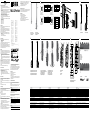 1
1
-
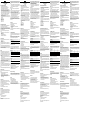 2
2
-
 3
3
-
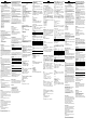 4
4


SICK MLG-2 ProNet Automation light grid Quickstart
- Categoria
- Brinquedos
- Tipo
- Quickstart
em outras línguas
Artigos relacionados
-
SICK MLG-2 ProNet FBM Quickstart
-
-
-
-
-
-
-
-
-