SICK WI180C-PB Profibus-Koppler Quickstart
- Tipo
- Quickstart

WI180C-PB
-------------------------------------------------- 8017973.126X 1219 COMAT -----------------------------------------
DEUTSCH
Probus-Koppler
Schnellanleitung
Sicherheitshinweise
> Die Montage, elektrische Installation und Konguration des
Geräts darf nur von fachlich qualiziertem Personal vorgenom-
men werden.
> Beachten Sie vor der Montage unbedingt die Betriebsanleitun-
gen der Gerätehersteller und stimmen Sie sich gegebenenfalls
vorher mit dem Hersteller über mögliche Montageorte ab.
> Beachten Sie bei der Montage und elektrischen Installation im-
mer die gültigen Arbeits-, Gesundheits- und Umweltvorschriften.
> Der Probus-Koppler darf nicht in Bereichen mit entzündlicher/
explosiver Atmosphäre eingesetzt werden!
> Beachten Sie bei der Installation unbedingt die elektrischen
Anschlusswerte.
> Tauschen Sie defekte oder beschädigte Kabel und Stecker
sofort aus.
> Tauschen Sie beschädigte oder defekte Komponenten – in
Abstimmung mit der SICK AG – sofort aus.
> Achten Sie bei der Montage unbedingt auf geeignete Befesti-
gungsmittel und deren spezische Anzugsdrehmomente.
> Sorgen Sie für eine konstante Stromversorgung des Geräts
innerhalb der vorgegebenen Parameter.
> Betreiben Sie den Probus-Koppler nur in den vorgegebenen
Betriebsparametern.
> Prüfen Sie die Funktionalität des Probus-Kopplers in regel-
mäßigen Abständen.
> Bauliche Veränderungen am Probus-Koppler sind nicht
zulässig!
Produktmerkmale
> Probus DP-V1 Slave
> Möglichkeit, per Funktionsbaustein zu kommunizieren
(z. B. SICK Funktionsbaustein, Siemens SFB52 oder
Siemens SFB53).
> Der vorkongurierte SICK Funktionsbaustein steht unter
www.sick.com zum Download bereit.
> Übertragungsraten von 9,6 KBit/s – 12 MBit/s
> Bis zu 16 Geräte über Systembus anschließbar
Übersicht
Der WI180C-PB ist ein Schnittstellen-Koppler, über den ange-
schlossene Geräte (z. B. WLL180T) mit dem Probus DP verbunden
werden können. Die Verbindung zu den jeweiligen Geräten erfolgt
über ein einfaches Bus-Stecksystem an der Seite des Kopplers.
Überlicherweise wird das gesamte System auf einer Hutschiene
nahe der Applikation angebracht.
Der Koppler unterstützt bis zu 16 angeschlossene Bus-Geräte, die
miteinander ebenfalls über das Stecksystem verbunden werden.
Diese Schnellanleitung beschreibt
> die Montagevorbereitung
> die Montage
> den elektrischen Anschluss
> die Konguration
Weitere Informationen
Weitere Informationen zum Probus-Koppler WI180C-PB nden Sie
in der Betriebsanleitung.
Wenden Sie sich bei Supportfragen an Ihr lokales Vertriebsbüro.
Weitere Informationen zu Produkten und Bestellungen nden Sie
unter:
www.sick.com
Mechanisch und elektrisch installieren
Vorbereitungen treen
1 Bereiten Sie die Spannungsversorgung und ein Datenkabel
gemäß B vor.
2 Montieren Sie eine geerdete Hutschiene im Bereich der
Applikation.
3 Verlegen Sie die beiden vorkonfektionierten Kabel ( B ) so,
dass sie leicht an die Anschlüsse des WI180C-PB angeschlos-
sen werden können.
Verwenden Sie ggf. Kabelkanäle, Kabelbinder und Zugentlas-
tungen.
Montieren
1 Klemmen Sie den WI180C-PB, wie in der Grak E dargestellt,
auf die Hutschiene.
2 Klemmen Sie die nachgeschalteten Geräte gemäß Monta-
geanleitung auf die Hutschiene .
3 Stecken Sie die nachgeschalteten Geräte auf den
5-Pin-Anschluss an der linken Seite des WI180C-PB ( F ).
Achten Sie dabei auf die korrekte Reihenfolge (siehe Betriebs-
anleitung zum jeweiligen Gerät).
4 Fixieren Sie die verbundenen Geräte auf der Hutschiene.
Anschließen
> Hinweis: Schalten Sie die Spannungsversorgung ab, bevor Sie
die Geräte anschließen.
1 Verbinden Sie den D-Sub-Stecker der Probusverbindung mit
dem Probus-Anschluss des WI180C-PB, und xieren Sie ihn
mit den Rändelschrauben.
2 Schließen Sie die M8-Buchse der Spannungsversorgung an
der Unterseite des WI180C-PB an, und schrauben Sie den
Stecker fest.
Konfigurieren und einschalten
1 Stellen Sie die vorgesehene Probus-Adresse an den beiden
Adress-Schaltern auf der Vorderseite des WI180C-PB ein ( G ).
Verwenden Sie dazu einen kleinen Schlitzschraubenzieher.
> Hinweis: Die Adresse kann im Bereich zwischen 01 und 99
liegen.
Der obere Drehschalter (x10) steht für ein Vielfaches von 10,
der untere Drehschalter (x1) für einen Wert zwischen 0 und 9.
2 Rufen Sie Ihre Entwicklungs- oder Kongurationsumgebung
auf.
ENGLISH
Probus coupler
Quick start guide
Safety notes
> Only professionally qualied personnel may carry out mounting,
electrical installation and conguration of the device.
> Before mounting the device, it is essential to take note of the
operating instructions provided by the device manufacturer and,
where applicable, to evaluate potential mounting locations with
the manufacturer in advance.
> When mounting and electrical installation work is being carried
out, always comply with applicable standard operating proce-
dures, health regulations and environmental regulations.
> The Probus coupler must not be used in areas with ammable/
explosive atmospheres!
> Be sure to observe electrical connection values during instal-
lation.
> Replace faulty or damaged cables and connectors immediately.
> Replace damaged or faulty components immediately and in
consultation with SICK AG.
> When mounting the device, it is imperative that you use suitable
mounting equipment and that you consider its specic tighten-
ing torques.
> Ensure a constant power supply to the device within the set
parameters.
> Only operate the Probus coupler at the specied operating
parameters.
> Regularly check that the Probus coupler is functioning properly.
> Structural modications to the Probus coupler are not
permitted!
Product features
> Probus DP-V1 slave
> Option of communicating using function block (e.g. SICK
function block, Siemens SFB52 or Siemens SFB53).
The precongured SICK function block is available for download
at www.sick.com.
3 Laden Sie die aktuelle Gerätedatei “Sick0E99.GSD” von
www.sick.com herunter.
4 Installieren Sie die Geräte-Datei “Sick0E99.GSD” in Ihrer
Projektierungssoftware.
5 Schalten Sie die Spannungsversorgung für den WI180C-PB
ein.
6 Warten Sie etwa 2 Sekunden, bis der WI180C-PB automatisch
Bereitschaft anzeigt ( C ).
> Transmission rates of 9.6 kbps – 12 Mbps
> Capability of connecting up to 16 devices over a system bus
Overview
The WI180C-PB is an interface coupler that can be used to link
connected devices (such as WLL180T) using Probus DP.
The corresponding devices are connected using a simple bus
connector system on the coupler side.
Normally the entire system is installed on a mounting rail near the
application.
The coupler supports up to 16 connected bus devices, which are
also connected to each other over the connector system.
This quick start guide outlines the following:
> Preparation for mounting
> Mounting
> Electrical connections
> Conguration
More information
You can nd more information about the WI180C-PB Probus
coupler in the operating instructions.
Please contact your local sales oce if you have any support
related queries.
More information on products and orders can be obtained at:
www.sick.com
Mechanical and electrical installation
Making preparations
1 Prepare the power supply and a data cable in accordance
with B .
2 Install a grounded mounting rail near the application.
3 Route both prefabricated cables ( B ) so that they can be
connected to the WI180C-PB connections with
ease. Use cable channels, cable ties or strain-release clamps
if necessary.
Installation
1 Clamp the WI180C-PB to the mounting rail as shown in the
picture E .
2 Clamp the downstream devices to the mounting rail according
to the installation instructions.
3 Plug the downstream devices into the 5-pin connection on
the left side of the WI180C-PB ( F ). While doing so, ensure
the order is correct (refer to the operating instructions for the
respective device).
4 Secure the connected devices in place on the mounting rail.
Connecting
> Note: Shut o the power supply before connecting the
devices.
1 Connect the D-Sub male connector for the Probus connec-
tion to the Probus terminal on the WI180C-PB and secure it
in place using the knurled screws.
2 Connect the M8 female connector of the power supply to the
bottom of the WI180C-PB and screw the male connector in
place.
Configuring and switching on
1 Congure the intended Probus address at the two address
switches on the front of the WI180C-PB ( G ).
Use a small slotted screwdriver to do so.
> Note: The address can be in a range between 01 and 99.
The upper rotary switch (x10) represents multiples of 10; the
lower rotary switch (x1) represents a value between 0 and 9.
2 Call up your development or conguration environment.
3 Download the current “Sick0E99 GSD” device le from
www.sick.com.
4 Install the “Sick0E99.GSD” device le in your project congu-
ration software.
5 Switch on the power supply for the WI180C-PB.
6 Wait about 2 seconds until the WI180C-PB automatically
indicates that it is ready ( C ).
FRANÇAIS
Coupleur Probus
Guide de démarrage rapide
Informations sur la sécurité
> Le montage, l’installation électrique et la conguration de
l’appareil doivent être conés uniquement au personnel
qualié.
> Avant le montage, respectez impérativement les notices
d’instruction des fabricants d’appareils et déterminez au préal-
able avec le fabricant les lieux de montage possibles.
> Lors du montage et de l’installation électrique, respectez
impérativement la réglementation sur le travail, la santé et
l’environnement.
> Le coupleur Probus ne doit pas être utilisé dans les atmo-
sphères inammables / explosives !
> Lors de l’installation, respectez impérativement les valeurs de
raccordement électriques.
> Remplacez immédiatement les câbles et les connecteurs mâles
endommagés.
> Remplacez immédiatement les composants endommagés ou
défectueux après avoir consulté la société SICK AG.
> Lors du montage, veillez à utiliser des accessoires de xation
adaptés et les couples de serrage spéciques.
> Veillez à l’alimentation électrique continue de l’appareil dans le
respect des paramètres prédénis.
> Exploitez le coupleur Probus uniquement dans les limites des
paramètres d’exploitation prédénis.
> Vériez régulièrement le fonctionnement du coupleur Probus.
> Les modications conceptuelles du coupleur Probus sont
strictement interdites !
Caractéristiques produit
> Probus DP-V1 Slave
> Possibilité de communiquer par module fonctionnel
(par ex. module fonctionnel SICK, Siemens SFB52 ou Siemens
SFB53).
Le module fonctionnel préconguré SICK peut être téléchargé
sur www.sick.com.
> Débits de 9,6 kbits/s à 12 Mbits/s
> Possibilité de raccorder jusqu’à 16 appareils via le bus système
Aperçu
Le coupleur d’interface WI180C-PB permet de relier les appareils
raccordés (par ex. WLL180T) à Probus DP.
Le raccordement à chaque appareil s’eectue via un système de
bus enchable simple côté coupleur.
Habituellement, le système complet est installé sur un rail DIN à
proximité de l’application.
Le coupleur prend en charge jusqu’à 16 appareils de bus raccor-
dés, reliés entre eux par le système enchable.
Ce guide de démarrage rapide présente
> la préparation du montage
> le montage
> le raccordement électrique
> la conguration
Informations supplémentaires
Pour des informations supplémentaires sur le coupleur
Probus WI180C-PB, voir la notice d’instruction.
Contactez votre revendeur pour toute question technique.
Des informations supplémentaires sur les produits et les
commandes sont fournies à l’adresse :
www.sick.com
Installation mécanique et électrique
Préparation
1 Préparez l’alimentation électrique et un câble de données
conformément à B .
2 Montez un rail DIN mis à la terre dans la zone de l’application.
3 Posez les deux câbles préassemblés ( B ) de manière à
faciliter leur raccordement aux connexions de WI180C-PB. Au
besoin, utilisez des gouttières de câbles, des serre-câbles et
des décharges de traction.
Montage
1 Fixez le WI180C-PB au rail DIN, comme dans l’illustration E .
2 Fixez les appareils en aval sur le rail DIN, conformément aux
instructions de montage.
3 Branchez les appareils en aval au connecteur à 5 broches du
côté gauche du WI180C-PB ( F ). Veillez à respecter l’ordre
(voir la notice d’instruction de l’appareil).
4 Fixez les appareils raccordés au rail DIN.
Raccordement
> Remarque : coupez l’alimentation électrique avant de raccor-
der les appareils.
1 Branchez le connecteur mâle D-Sub de la connexion Probus
à la connexion Probus du WI180C-PB et xez-le avec les vis
moletées.
2 Branchez le connecteur femelle M8 de l’alimentation élec-
trique au bas du WI180C-PB et vissez le connecteur mâle.
Configuration et mise en route
1 Réglez l’adresse Probus prévue sur les deux commutateurs
d’adresse à l’avant du WI180C-PB ( G ).
Utilisez pour cela un petit tournevis à lame plate.
> Remarque : l’adresse peut être comprise entre 01 et 99.
L’interrupteur rotatif supérieur (x10) correspond à un multiple
de 10, l’interrupteur rotatif inférieur (x1) à une valeur comprise
entre 0 et 9.
2 Ouvrez votre environnement de développement ou de congu-
ration.
3 Téléchargez le chier d’appareil actuel «Sick0E99.GSD» à
l’adresse www.sick.com.
4 Installez le chier d’appareil «Sick0E99.GSD» dans votre
logiciel de développement.
5 Activez l’alimentation électrique du WI180C-PB.
6 Attendez environ 2 secondes jusqu’à ce que le WI180C-PB
indique qu’il est opérationnel ( C ).
PORTUGUÊS
Acoplador Probus
Manual rápido
Avisos de segurança
> A montagem, a instalação elétrica e a conguração do aparelho
só podem ser feitas por pessoal qualicado.
> Antes da montagem, observe impreterivelmente os manuais
de instruções dos fabricantes dos aparelhos e, se necessário,
combine com o fabricante os possíveis locais de montagem.
> Para a montagem e a instalação elétrica, observe sempre os
regulamentos de proteção ambiental, saúde e trabalho.
> O acoplador Probus não deve ser usado em áreas com atmos-
fera inamável/explosiva!
> Para a instalação, observe impreterivelmente os valores da
conexão elétrica.
> Troque os conectores e cabos danicados ou defeituosos
imediatamente.
> Troque imediatamente os componentes danicados ou de-
feituosos – em consulta com a SICK AG.
> Para a montagem, devem ser usados impreterivelmente
dispositivos de xação adequados e os seus torques de aperto
especícos.
> Providencie a constante alimentação de tensão do aparelho
dentro dos parâmetros indicados.
> Só opere o acoplador Probus com os parâmetros de operação
indicados.
> Verique a funcionalidade do acoplador Probus em intervalos
regulares.
> Modicações na estrutura do acoplador Probus não são
permitidas!
Características do produto
> Probus DP-V1 Slave
> Possibilidade de comunicar por módulo funcional (p. ex.
módulo funcional SICK, Siemens SFB52 ou Siemens SFB53).
O módulo funcional pré-congurado SICK está à disposição
para o download em www.sick.com.
> Taxas de transmissão de 9,6 KBit/s – 12 MBit/s
> Até 16 aparelhos conectáveis através do barramento de
sistema
Visão Geral
O WI180C-PB é um acoplador de interface, através do qual os
aparelhos conectados (p. ex. WLL180T) podem ser ligados ao
Probus DP. A ligação aos respectivos aparelhos é feita através
de um simples sistema de encaixe de barramento no lado do
acoplador.
Normalmente, o sistema completo é colocado sobre um trilho
próximo à aplicação.
O acoplador é compatível com até 16 aparelhos de barramento
conectados que são ligados entre si também através do sistema
de encaixe.
O manual rápido descreve
> a preparação da montagem
> a montagem
> a conexão elétrica
> a conguração
Outras informações
Outras informações sobre o acoplador Probus WI180C-PB
encontram-se no Manual de instruções.
Em caso de dúvidas, entre em contato com o seu representante de
vendas local.
Outras informações sobre os produtos e as encomendas
encontram-se em:
www.sick.com
Instalação mecânica e elétrica
Preparações
1 Providencie a alimentação de tensão e um cabo de dados
segundo B .
2 Monte um trilho ligado à terra na área da aplicação.
3 Assente ambos os cabos pré-confeccionados ( B ) de modo
que possam ser facilmente ligações às conexões do
WI180C-PB.
Use, se necessário, canais de cabos, braçadeiras de cabos e
trações de cabos.
Montar
1 Conecte o WI180C-PB, como mostrado no gráco E , no
trilho.
2 Conecte os aparelhos posteriores, de acordo com as instru-
ções de montagem, sobre o trilho.
3 Encaixe os aparelhos posteriores na conexão de 5 pinos no
lado esquerdo do WI180C-PB ( F ). Observe a sequência
correta (ver o Manual de instruções ao respectivo aparelho).
4 Fixe os aparelhos conectados no trilho.
Conectar
> Nota: desligue a alimentação de tensão antes de conectar os
aparelhos.
1 Ligue o sub-conector macho D com a ligação de Probus
com a conexão de probus do WI180C-PB e xe-o com os
parafusos serrilhados.
2 Conecte o conector fêmea M8 da alimentação de tensão no
lado inferior do WI180C-PB e parafuse o conector macho.
Configurar e ligar
1 Ajuste os endereços Probus indicados em ambos os inter-
ruptores de endereço no lado dianteiro do WI180C-PB ( G ).
Use para isso uma pequena chave de fenda.
> Nota: o endereço pode estar na faixa entre 01 e 99. O inter-
ruptor rotativo superior (x10) representa uma multiplicação
por 10, o interruptor rotativo inferior (x1) um valor entre 0 e 9.
2 Chame o seu ambiente de conguração ou desenvolvimento.
3 Carregue o atual arquivo do aparelho “Sick0E99.GSD” de
www.sick.com.
4 Instale o arquivo do aparelho “Sick0E99.GSD” no seu softwa-
re de projetação.
5 Ligue a alimentação de tensão para o WI180C-PB.
6 Espere aproximadamente 2 segundos até que o WI180C-PB
mostre automaticamente a operacionalidade ( C ).
ITALIANO
Accoppiatore Probus
Guida sintetica
Avvertenze di sicurezza
> Il montaggio, l’installazione elettrica e la congurazione
dell’apparecchio devono essere eseguiti esclusivamente da
personale tecnico qualicato.
> Prima del montaggio osservare assolutamente le istruzioni per
l’uso del costruttore dell’apparecchio ed eventualmente concor-
dare prima con il costruttore possibili luoghi di montaggio.
> Durante il montaggio e l’installazione elettrica prestare sempre
attenzione alle disposizioni vigenti in materia di lavoro, salute
e ambiente.
> L’accoppiatore Probus non deve essere utilizzato in ambienti
con atmosfera inammabile/esplosiva!
> Durante l’installazione prestare assolutamente attenzione ai
valori di allacciamento elettrico.
> Sostituire immediatamente eventuali cavi e connettori difettosi
o danneggiati.
> Sostituire immediatamente i componenti danneggiati o difettosi
previo accordo con SICK AG.
> Durante il montaggio prestare assolutamente attenzione a
utilizzare strumenti di ssaggio adeguati e alle relative coppie di
serraggio speciche.
> Assicurare una costante alimentazione elettrica
dell’apparecchio entro i parametri predeniti.
> Utilizzare l’accoppiatore Probus solo entro i parametri
d’esercizio predeniti.
> Controllare la funzionalità dell’accoppiatore Probus a intervalli
di tempo regolari.
> Non sono ammesse modiche costruttive all’accoppiatore
Probus!
Caratteristiche prodotto
> Probus DP-V1 Slave
> Possibilità di comunicare tramite blocco funzionale (ad es.
blocco funzionale SICK, Siemens SFB52 o Siemens SFB53).
Il blocco funzionale SICK precongurato può essere scaricato
all’indirizzo www.sick.com.
> Velocità di trasmissione di 9,6 KBit/s – 12 MBit/s
> Possibilità di collegare no a 16 apparecchi tramite bus di
sistema
Panoramica
Il WI180C-PB è un accoppiatore di interfaccia che consente di col-
legare apparecchi collegati (ad es. WLL180T) con il Probus DP.
Il collegamento ai rispettivi apparecchi avviene tramite un sistema
bus a innesto semplice sul lato dell’accoppiatore.
Generalmente l’intero sistema viene montato su una guida DIN nei
pressi dell’applicazione.
L’accoppiatore supporta no a 16 apparecchi bus collegati,
anch’essi collegati fra loro tramite il sistema a innesto.
Questa guida sintetica descrive
> la preparazione per il montaggio
> il montaggio
> l’allacciamento elettrico
> la congurazione
Ulteriori informazioni
Ulteriori informazioni sull’accoppiatore Probus WI180C-PB sono
riportate nelle istruzioni per l’uso.
Per domande di supporto rivolgersi al proprio rivenditore locale.
Per informazioni dettagliate sui prodotti e sulle ordinazioni consul-
tare il sito:
www.sick.com
Installazione meccanica ed elettrica
Preparazioni
1 Predisporre l’alimentazione elettrica e un cavo dati come
descritto in B .
2 Montare una guida DIN messa a terra nell’area dell’appli-
cazione.
3 Posare entrambi i cavi preconfezionati ( B ) in modo tale che
possano essere facilmente collegati agli attacchi del
WI180C-PB .
Se necessario, utilizzare canaline portacavi, fascette per cavi
e dispositivi di scarico della trazione.
Montaggio
1 Fissare il WI180C-PB sulla guida DIN come illustrato nella
gura E .
2 Fissare sulla guida DIN gli apparecchi collegati in serie come
descritto nelle istruzioni di montaggio.
3 Inserire gli apparecchi collegati in serie nell’attacco a 5 pin
sul lato sinistro del WI180C-PB ( F ). Prestare attenzione alla
sequenza corretta (vedi le istruzioni per l’uso del rispettivo
apparecchio).
4 Fissare gli apparecchi collegati sulla guida DIN.
Collegamento
> Avvertenza: disattivare l’alimentazione elettrica prima di
collegare gli apparecchi.
1 Collegare il connettore D-sub del collegamento Probus
all’attacco Probus del WI180C-PB e ssarlo con le viti a
testa zigrinata.
2 Collegare la presa M8 dell’alimentazione elettrica al lato
inferiore del WI180C-PB e serrare a fondo il connettore.
Configurazione e attivazione
1 Impostare l’indirizzo Probus previsto su entrambi gli interrut-
tori di indirizzo sul lato anteriore del WI180C-PB ( G ).
A tale scopo utilizzare un piccolo cacciavite a taglio.
> Avvertenza: l’indirizzo può trovarsi nel campo compreso tra
01 e 99. L’interruttore girevole superiore (x10) è per un
multiplo di 10, quello inferiore (x1) per un valore compreso
tra 0 e 9.
2 Richiamare il proprio ambiente di sviluppo o congurazione.
3 Scaricare il le attuale dell’apparecchio “Sick0E99.GSD” dal
sito www.sick.com.
4 Installare il le dell’apparecchio “Sick0E99.GSD” nel proprio
software di progettazione.
5 Attivare l’alimentazione elettrica per il WI180C-PB.
6 Attendere circa 2 secondi nché il WI180C-PB visualizza
automaticamente l’indicazione di operatività ( C ).
BZ int49
Detailed addresses and further locations at www.sick.com
Australia
Phone +61 (3) 9457 0600
1800 33 48 02 –
tollfree
Austria
Phone +43 (0) 2236 62288-0
Belgium/Luxembourg
Phone +32 (0) 2 466 55 66
Brazil
Phone +55 11 3215-4900
Canada
Phone +1 905.771.1444
Czech Republic
Phone +420 234 719 500
Chile
Phone +56 (2) 2274 7430
China
Phone +86 20 2882 3600
Denmark
Phone +45 45 82 64 00
Finland
Phone +358-9-25 15 800
France
Phone +33 1 64 62 35 00
Germany
Phone +49 (0) 2 11 53 010
Greece
Phone +30 210 6825100
Hong Kong
Phone +852 2153 6300
Hungary
Phone +36 1 371 2680
India
Phone +91-22-6119 8900
Israel
Phone +972 97110 11
Italy
Phone +39 02 27 43 41
Japan
Phone +81 3 5309 2112
Malaysia
Phone +603-8080 7425
Mexico
Phone +52 (472) 748 9451
Netherlands
Phone +31 (0) 30 229 25 44
New Zealand
Phone +64 9 415 0459
0800 222 278 – tollfree
Norway
Phone +47 67 81 50 00
Poland
Phone +48 22 539 41 00
Romania
Phone +40 356-17 11 20
Russia
Phone +7 495 283 09 90
Singapore
Phone +65 6744 3732
Slovakia
Phone +421 482 901 201
Slovenia
Phone +386 591 78849
South Africa
Phone +27 10 060 0550
South Korea
Phone +82 2 786 6321/4
Spain
Phone +34 93 480 31 00
Sweden
Phone +46 10 110 10 00
Switzerland
Phone +41 41 619 29 39
Taiwan
Phone +886-2-2375-6288
Thailand
Phone +66 2 645 0009
Turkey
Phone +90 (216) 528 50 00
United Arab Emirates
Phone +971 (0) 4 88 65 878
United Kingdom
Phone +44 (0)17278 31121
USA
Phone +1 800.325.7425
Vietnam
Phone +65 6744 3732
SICK AG, Erwin-Sick-Strasse 1, D-79183 Waldkirch
2006/42/EC
NO
SAFETY

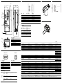
A Dimensional drawings
WI180C-PB
Versorgungsspannung Supply voltage Tension d'alimentation Tensão de alimentação Tensione di alimentazione 12 – 24 VDC ± 10%
Leistungsaufnahme Power consumption Puissance absorbée Consumo de energia Potenza assorbita 2 W
Einschaltverzögerung (WI180C-PB) Switch-on delay (WI180C-PB) Temporisation de mise en route (WI180C-PB) Atraso de ligação (WI180C-PB) Ritardo di attivazione (WI180C-PB) 500 ms
Einschaltverzögerung (Gesamtsystem) Switch-on delay (complete system) Temporisation de mise en route (système complet) Atraso de ligação (sistema completo) Ritardo di attivazione (sistema completo) 2000 ms
Profil Profile Profil Perfil Profilo Profibus DP-V1
Maximale Anzahl Module Maximum number of modules Nombre maximum de modules Número máximo de módulos Numero massimo di moduli 16
Übertragungsraten in kBit/s Transmission rates in kbps Débits en kbits/s Taxa de transmissão em kBit/s Velocità di trasmissione in kBit/s 9.6 / 19.2 / 45.45 / 93.75 / 187.5 / 500 /
1500 / 3000 / 6000 / 12,000
Maximale Entfernung zwischen Knoten Maximum distance between nodes Distance maximale entre les nœuds Distância máxima entre os nós Distanza massima tra nodi 1200 m @ 9.6 – 93.75 kbps
1000 m @ 187.5 kbps
400 m @ 500 kbps
200 m @ 1500 kbps
100 m @ 3000 – 12,000 kbps
Prozessdaten Process data Données de processus Dados de processo Dati di processo 2x output, 1x input, 14 bits of received light
Asynchrone Daten Asynchronous data Données asynchrones Dados assíncronos Dati asincroni Fieldbus index map
Übertragungsschnittstelle Transmission interface Interface de transmission Interface de transmissão Interfaccia di trasmissione RS-485
Spannungsversorgung Power supply Alimentation électrique Alimentação de tensão Alimentazione elettrica M8 plug connector, 4-pin
Weitere Schnittstellen Additional interfaces Autres interfaces Outras interfaces Altre interfacce Bus male connector, 5-pin, internal system
bus
D-Sub, 9-pin, Profibus
Rauschunempfindlichkeit (Kabellänge ≤30 m) Noise immunity (length of cable ≤30 m) Insensibilité au bruit (longueur de câble ≤ 30 m) Imunidade contra ruídos (comprimento do cabo
≤30 m)
Immunità al rumore (lunghezza del cavo ≤30 m) In accordance with EN 61000-6-2/EN
61131-2
Abstrahlung Emissions Rayonnement Radiação Emissioni Irradiate In accordance with EN 55011, Class A
Schutzklasse Protection class Classe de protection Classe de proteção Classe di protezione 3
Kurzschlusssicherheit Short-circuit protection Protection contre les courts-circuits Proteção contra curto-circuito Protezione anti-cortocircuito In accordance with VDE 0160
Schutzkategorie Protection category Indice de protection Categoria de proteção Grado di protezione IP50
Vibrationsunempfindlichkeit Sensitivity to vibrations Insensibilité aux vibrations Imunidade contra vibrações Immunità alle vibrazioni IEC 68, 10 – 55 Hz
Schockunempfindlichkeit Shock resistance Insensibilité aux chocs Imunidade contra choques Immunità agli urti IEC 68, 500 m/s² (~50 G)
Maße (HxBxT) in mm Dimensions (HxWxD) in mm Dimensions (HxLxP) en mm Dimensões (AxLxP) em mm Quote (AxLxP) in mm 39.2 x 102.55 x 39
Anschlüsse Connections Raccordements Conexões Collegamenti M8, 4-pin, power supply
D-Sub, 9-pin, Profibus
Bus male connector, 5-pin, bus connector
Luftfeuchtigkeit (Betrieb/ Lagerung) Air humidity (operation/storage) Humidité de l'air (fonctionnement / stockage) Umidade do ar (operação/ armazenagem) Umidità dell'aria (esercizio/immagazzinamento) 35 – 85% relative humidity
Temperaturbereich (Lagerung) Temperature range (storage) Plage de températures (stockage) Faixa de temperatura (armazenagem) Intervallo di temperatura (immagazzinamento) -40 – +70 °C
Temperaturbereich (Betrieb, ≤3 angeschlossene
Geräte)
Temperature range (operation, ≤ 3 connected
devices)
Plage de températures (fonctionnement, ≤ 3
appareils raccordés)
Faixa de temperatura (operação, ≤3 aparelhos
conectados)
Intervallo di temperatura (esercizio, ≤3 apparecchi
collegati)
-25 – +55 °C
Temperaturbereich (Betrieb, ≤8 angeschlossene
Geräte)
Temperature range (operation, ≤ 8 connected
devices)
Plage de températures (fonctionnement, ≤ 8
appareils raccordés)
Faixa de temperatura (operação, ≤8 aparelhos
conectados)
Intervallo di temperatura (esercizio, ≤8 apparecchi
collegati)
-25 – +50 °C
Temperaturbereich (Betrieb, ≤16 angeschlossene
Geräte)
Temperature range (operation, ≤ 16 connected
devices)
Plage de températures (fonctionnement, ≤ 16
appareils raccordés)
Faixa de temperatura (operação, ≤16 aparelhos
conectados)
Intervallo di temperatura (esercizio, ≤16 apparecchi
collegati)
-25 – +45 °C
B Connections
D Accessories
E Installation on DIN rail G Address switches
F Add a device
C LED display
39
25,3
27,1
92
102,55
38,2
33,2
18,835
37,9
10
10,4
No. Description
1 PWR-LED
2 RUN-LED
3 COM-LED
4 ERR-LED
5 x10 and x1 address switches
6 M8 power connection, 4-pin
7 Bus male connector, 5-pin
8 Profibus connection, D-Sub, 9-pin
Probus (D-Sub, 9-Pin)
12345
6789
Pin Description
1 Not assigned
2 Not assigned
3 RxD+/TxD+
4 RTS
5 DGND
6 +5 VDC
7 Not assigned
8 RxD-/TxD-
9 Not assigned
Power (M8, 4-Pin)
Pin Description
1 +12–24 VDC
2 Not assigned
3 GND
4 Not assigned
4
2
1 3
PWR RUN COM ERR Description
– – – – No power supply
X – – – Power supply established, device initialized
X X – – Initialization completed
X X X – Communication established with DP master, function free of errors
X Flashes acyclically –/X X/Flashes acyclically No communication with bus devices or fatal error
X –(100 ms) –/X X/Flashes acyclically Error present
X –/Flashes acyclically –/X X Incorrect configuration
X –/Flashes cyclically –/X Flashes acyclically Configuration not completed
X –/X – Flashes cyclically No communication with DP master
Part No. Type Description
6009870 D0L-0804-G02M Female, M8, 4-pin, straight,
2 m cable
6009872 D0L-0804-G05M Female, M8, 4-pin, straight,
5 m cable
6009871 D0L-0804-W02M Female, M8, 4-pin, angled, 2 m
cable
6009873 D0L-0804-W05M Female, M8, 4-pin, angled, 5 m
cable
5313011 BF-EB01-W190 Rail end cap for block mounting
UL Satisfaction Ratings
Power input Power output Connected device quantity Maximum surrounding air temperature
12 ... 30 VDC
max. 0.45 A
Class 2
connect up to
3 devices
50 °C
12 ... 30 VDC
max. 1.28 A
Class 2
12 ... 30 VDC
max. 0.8 A
Class 2
connect up to
8 devices
50 °C
12 ... 30 VDC
max. 1.12 A
Class 2
connect up to
16 devices
45 °C

WI180C-PB
ESPAÑOL
Acoplador Probus
Guía de inicio rápido
Instrucciones de seguridad
> El montaje, la instalación eléctrica y la conguración de este
dispositivo deben ser realizados exclusivamente por personal
con la debida cualicación técnica.
> Antes de proceder al montaje, tenga en cuenta las instrucciones
de uso del fabricante del dispositivo y, si es necesario, consulte
previamente con él las posibles ubicaciones de montaje.
> Durante el montaje y la instalación eléctrica, observe siempre
la normativa vigente en materia de salud y seguridad y medio
ambiente.
> El acoplador Probus no puede usarse en áreas con atmósferas
potencialmente explosivas o inamables.
> Durante la instalación del dispositivo, observe los valores de la
conexión eléctrica.
> Cambie inmediatamente los cables y conectores defectuosos
o dañados.
> Cambie inmediatamente los componentes defectuosos o
dañados (de acuerdo con SICK AG).
> Durante el montaje del dispositivo deberá usar los medios de
jación adecuados y sus pares de apriete especícos.
> Proporcione una fuente de alimentación constante al disposi-
tivo dentro de los parámetros establecidos.
> Utilice el acoplador Probus únicamente dentro de los parámet-
ros de funcionamiento especicados.
> Compruebe la funcionalidad del acoplador Probus a intervalos
regulares.
> No está permitido realizar modicaciones constructivas en el
acoplador Probus.
Características del producto
> Esclavo Probus DP-V1
> Opción de comunicación vía bloque de funciones (p. ej., bloque
de funciones SICK, Siemens SFB52 o Siemens SFB53).
El bloque de funciones SICK precongurado se encuentra
disponible para su descarga en www.sick.com.
> Velocidad de transmisión de 9,6 kbps – 12 Mbps
> Se pueden conectar hasta 16 dispositivos a través del bus del
sistema
Visión general
El WI180C-PB es un acoplador de interfaces que puede usarse
para acoplar los dispositivos conectados
(p. ej., WLL180T) a Probus DP. Los distintos dispositivos se
conectan mediante un sistema de enchufe de bus sencillo ubicado
en un lado del acoplador.
Por lo general, todo el sistema se monta sobre un riel de perl de
sombrero próximo a la aplicación.
El acoplador soporta hasta 16 dispositivos de bus conectados, que
también están interconectados a través del sistema de enchufe.
Esta guía de inicio rápido describe:
> Los preparativos de montaje
> El montaje
> La conexión eléctrica
> La conguración
Información adicional
En las instrucciones de uso podrá encontrar más información sobre
el acoplador Probus WI180C-PB.
Si tiene alguna duda relacionada con el soporte técnico, póngase
en contacto con su ocina de ventas local.
Si desea obtener más información sobre productos y pedidos,
visite:
www.sick.com
Instalación mecánica y eléctrica
Preparativos
1 Prepare la fuente de alimentación y un cable de datos según
gura B .
2 Monte un riel de perl de sombrero en la zona de la aplica-
ción.
3 Tienda los dos cables preconfeccionados ( B ) de modo que
puedan conectarse con facilidad a los conectores
del WI180C-PB. Si es necesario, utilice canales para cables,
abrazaderas y sistemas de descarga de tracción.
Montaje
1 Fije el WI180C-PB en el riel de montaje como se muestra en la
imagen E .
2 Fije los dispositivos conectados en serie en el riel de montaje
como se muestra en las instrucciones de montaje.
3 Enchufe los dispositivos conectados aguas abajo en el
conector de 5 terminales ubicado en el lado izquierdo del
WI180C-PB ( F ). Preste atención a que el orden sea el
correcto (consulte las instrucciones de uso del dispositivo
correspondiente).
4 Fije los dispositivos conectados en el riel de montaje.
Conexión
> Indicación: Desconecte la fuente de alimentación antes de
conectar los dispositivos.
1 Conecte el conector macho D-Sub de la conexión Probus
con el puerto Probus del WI180C-PB y fíjelo con los tornillos
moleteados.
2 Conecte el conector hembra M8 de la fuente de alimentación
ubicada en la parte inferior del WI180C-PB y atornille rme-
mente el conector macho.
Configuración y conexión
1 Establezca la dirección Probus proporcionada en los dos
conmutadores de dirección que se encuentran en la parte
frontal del WI180C-PB ( G ).
Utilice para ello un destornillador de ranura longitudinal
pequeño.
> Indicación: La dirección puede estar en el rango entre 01
y 99. El conmutador giratorio superior (x10) representa un
中文
Probus连接器
快速操作指南
安全须知
> 设备的组装,电气安装和配置只能由专业人员操作。
> 请在安装前务必仔细阅读设备供应商提供的操作手
册,如有可能,应与供应商先行确认安装位置。
> 请在组装设备和电气安装时严格遵守劳动、健康和环
境方面的相关法律法规,
> 禁止在易燃易爆环境中使用Probus连接器。
> 请在安装时注意连接电路的负载。
> 如发现坏的连接线或插头应立即更换。
> 如发现坏的零部件应在咨询SICK AG后立即更换。
> 请务必在安装时使用合适的固定工具,其应具备合
适的扭矩。
> 请为设备连接允许范围内的稳定供电电源。
> 仅允许在正确的操作参数范围内使用Probus连接
器。
> 定期对Probus连接器的功能进行检查。
> 禁止对Probus连接器做结构上的改动。
> 产品特点
> Probus DP-V1 Slave
> 可通过功能模块完成通信(如SICK功能模
块,Siemens SFB52或Siemens SFB53)。
已预设的SICK功能模块可在SICK官网下载:
www.sick.com
> 传输速率为9.6 KBit/s – 12 MBit/s
> 系统总线上最多可连接16个设备
日本語
PROFIBUSカプラ
簡易説明書
安全上の注意事項
> 機器の取付け、電気的設置および設定を行うのは、
有資格の専門家に限られています。
> 取付け前には必ず機器メーカーの取扱説明書に注意
し、必要な場合はメーカーと可能な取付場所につい
て事前に話し合ってください。
> 取付けおよび電機的設置の際には、常に現行の作業
規則、健康規則および環境規則に従ってください。
> PROFIBUSカプラは、可燃性および爆発性雰囲気で
は使用してはいけません!
> 設置の際は、電源要件必ず確認してください。
> 故障または損傷したケーブルおよびオスコネクタは
すぐに交換してください。
> 損傷または故障したコンポーネントは – SICK AGの
同意を得た上で – すぐに交換してください。
> 取付け時には、必ず適切な固定具を使用し、その固
有の締付トルクを守ってください。
> 機器の供給電源が指定されたパラメータ内に一定に
おさまるように注意してください。
> 必ず指定された操作パラメータでPROFIBUSカプラ
を操作してください。
> PROFIBUSカプラの機能性を定期的に点検してく
ださい。
> PROFIBUSカプラを構造上変更することは禁じら
れています!
> 製品特性
> PROFIBUS DP-V1 Slave
> 機能モジュール経由の通信が可能(例えばSICK機
能モジュール、Siemens SFB52または
Siemens SFB53)。
事前に設定したSICK機能モジュールは
www.sick.comからダウンロードできます。
> 伝送速度 9.6 KBit/s~12 MBit/s
> システムバスを介して最大16台の機器を接続可能
múltiplo de 10; el inferior (x1), un valor entre 0 y 9.
2 Acceda a su entorno de desarrollo o conguración.
3 Descargue el archivo de dispositivo actual “Sick0E99.GSD”
desde www.sick.com.
4 Instale el archivo de dispositivo “Sick0E99.GSD” en su
software de conguración.
5 Conecte la fuente de alimentación del WI180C-PB.
6 Espere aprox. 2 segundos hasta que el WI180C-PB indique
automáticamente que está operativo ( C ).
Русский язык
Адаптер Probus
Краткое руководство
Указания по безопасности
> Установку, электромонтаж и настройку устройства
разрешается выполнять только квалифицированным
специалистам.
> Перед установкой устройства необходимо изучить
руководство по эксплуатации предприятия-изготовителя и при
необходимости согласовать с ним место установки.
> При установке и электромонтаже следует строго соблюдать
действующие правила охраны труда и техники безопасности,
требования нормативных документов по охране здоровья и
защите окружающей среды.
> Запрещается использовать адаптер Probus в зонах с
опасностью воспламенения и во взрывоопасной атмосфере!
> При электромонтаже следует строго соблюдать заданные
параметры подключения.
> Неисправные и поврежденные кабели подлежат немедленной
замене.
> Неисправные и поврежденные компоненты необходимо
немедленно заменять по согласованию с компанией SICK.
> При установке следует использовать соответствующие
крепежные изделия и соблюдать предписанные моменты их
затяжки.
> Необходимо обеспечить постоянное электропитание
устройства с заданными параметрами.
> Адаптер Probus разрешается эксплуатировать только с
заданными рабочими параметрами.
> Необходимо периодически проверять работоспособность
адаптера Probus.
> Запрещается вносить в конструкцию адаптера какие-либо
изменения!
Характеристики продукта
> Ведомое устройство Probus DP-V1.
> Возможность соединения через функциональный модуль
(например, функциональный модуль SICK, Siemens SFB52
или Siemens SFB53).
Предварительно настроенный функциональный модуль SICK
можно загрузить с веб-сайта www.sick.com.
> Скорость передачи данных — от 9,6 кбит/с до 12 Мбит/с.
> Через системную шину может быть подключено
до 16 устройств.
Обзор
WI180C-PB представляет собой адаптер, с помощью которого
устройства (например, WLL180T) могут соединяться с Pro-
bus DP. Подключение устройств осуществляется с помощью
простой системы модульных разъемов на стороне адаптера.
Как правило, вся система размещается на монтажной шине
вблизи места применения.
Адаптер поддерживает до 16 подключенных шинных устройств,
которые соединяются между собой модульными разъемами.
Данное краткое руководство содержит описание следующих
операций:
> подготовки к монтажу;
> монтажа;
> электрических подключений;
> настройки.
Дополнительная информация
Дополнительная информация об адаптере Probus WI180C-PB
приведена в руководстве по эксплуатации.
По возникающим вопросам необходимо обращаться к местным
дилерам.
Дополнительная информация по продуктам и заказам приведена
на веб-сайте
www.sick.com.
Механический и электрический монтаж
Подготовительные работы
1 Подготовить источник питания и кабель передачи данных в
соответствии с B .
2 Установить монтажную шину с заземлением в зоне приме-
нения.
3 Проложить два предварительно подготовленных кабеля ( B )
таким образом, чтобы их можно было подключить к устрой-
ству WI180C-PB. При необходимости следует использовать
кабельные каналы, кабельные стяжки и устройства для
разгрузки от натяжения.
Монтаж
1 Закрепить устройство WI180C-PB на монтажной шине, как
показано на рисунке.
2 Закрепить подключаемые устройства на монтажной шине в
соответствии с руководством по монтажу.
3 Подсоединить подключаемые устройства через 5-каналь-
ный разъем на левой стороне WI180C-PB ( F ). Соблюдать
последовательность подключения (см. руководство по
эксплуатации соответствующего устройства).
4 Закрепить подсоединяемые устройства на монтажной
шине.
Подключение
> Указание: перед подключением устройств отсоединить
источник питания.
1 Вставить штекер D-Sub Probus в разъем Probus устрой-
ства WI180C-PB и зафиксировать его винтами с накатанной
головкой.
2 Подключить источник питания через разъем M8 на нижней
стороне устройства WI180C-PB и закрепить его винтами.
概览
WI180C-PB是一个端口连接器,通过它可将设备
(如WLL 180T)与Probus DP网络连接起来。每个设备的
连接可通过连接器侧面的现场总线插口实现。
通常情况下,整个系统都被安装在应用点附近的一条导轨
上。
连接器支持16个现场总线设备的连接,这些设备同样也通过
插入系统相互连接。
本快速操作指南包括以下内容
> 安装准备
> 安装
> 电气连接
> 配置
其他信息
其他关于WI180C-PB Probus连接器的信息请参见操
作手册。
如需技术支持请联系所在地办事处。
更多产品及订购信息详见SICK官网:
www.sick.com
机械及电气安装
准备
1 根 据 B 准备电源和数据连接线
2 在应用区域内安装一条导轨
3 请预先处理好两根连接线 ( B ) ,使它们能直接连
接到WI180C-PB的接口上。如有需要,可以使用线
槽, 扎带和电缆固定头。
安装
1 如图所示,将WI180C-PB嵌入导轨中。
2 根据安装说明的要求将下游设备也夹紧在导轨上。
3 将下游设备连接到WI180C-PB左侧的5针接口上( F )。
请注意先后顺序(参见相关设备的操作手册)。
4 将连接好的设备固定在导轨上。
连接
> 注意事项:在连接设备前,请务必切断电源。
1 将Probus连接器的D-Sub插头插入 WI180C-PB的
Probus接口中,并用蝶形螺丝固定。
2 用M8连接器将电源接入WI180C-PB的底部,拧紧
插头。
配置及接通
1 将WI180C-PB正面的两个数字旋钮调成指定的
Probus地址编码请用一把小螺丝刀辅助操作。
> 注意事项:地址编码范围在01-99之间上方旋钮
(x10)表示十位数,下方旋钮(x1)表示0-9之间
的个位数。
2 请调出您的开发或配置界面
3 从SICK官网www.sick.com下载最新的“Sick0E99.
GSD”设备文件。
4 在您的设计软件中安装设备文件“Sick0E99.GSD”。
5 接通WI180C-PB 的电源。
6 等待2秒左右,WI180C-PB将自动显示已准备完成
( C ).
概要
WI180C-PBはインターフェースカプラで、接続されてい
る機器(例えばWLL180T)を介してPROFIBUS DPと接続
できます。それぞれの機器への接続は、カプラ側の簡単な
バス接続システムを介して行われます。
通常、システム全体はアプリケーション近くのトップハッ
トレール上に取り付けられます。
カプラは接続された最大16台のバス機器をサポートし、
これらは同様にプラグインシステムを介して相互に接続
します。
この簡易説明書は以下について記載しています。
> 取付準備
> 取付
> 電気的接続
> 設定
詳細情報
PROFIBUSカプラWI180C-PBの詳細については、取
扱説明書に記載されています。
サポートに関するご質問は、現地の販売事務所までお
問い合わせください。
製品および注文の詳細については当社のホームページ
をご覧ください:
www.sick.com
機械的および電気的設置
準備
1 供給電圧とデータケーブルをBに従って準備しま
す。
2 接地したトップハットレールをアプリケーション
エリアに取り付けます。
3 予め組立てられた両ケーブル(B)を敷設
し、WI180C-PBの接続部に簡単に接続できるよう
にします。必要に応じてケーブルダクト、ケーブ
ルタイおよびストレインリリーフを使用します。
取付
1 図のようにWI180C-PBをトップハットレールに挟
みます。
2 取扱説明書に従って下流機器をトップハットレー
ルに挟みます。
3 下流機器をWI180C-PB左側の5ピン接続に差込み
ます( F )。その際、正しい順序に注意します(各機
器の取扱説明書を参照)。
4 接続された機器をトップハットレールに固定しま
す。
接続
> 注意事項:機器を接続する前に、供給電圧を遮断
してください。
1 PROFIBUS接続のD-Subオスコネクタを
WI180C-PBのPROFIBUS接続部と接続し、ローレ
ットネジで固定します。
2 供給電圧のM8メスコネクタをWI180C-PBの下側
に接続し、オスコネクタを締め付けます。
設定および電源投入
1 WI180C-PB前面の両方のアドレススイッチに指定
されたPROFIBUSアドレスを設定します。これに
は小型のスロットスクリュードライバを使用しま
す。
> 注意事項:アドレスは01~99の範囲内で可能で
す。上のロータリースイッチ(x10)は10の倍
数、下のロータリースイッチ(x1)は0~9に該当
します。
2 開発環境または設定環境を呼び出します。
3 最新の機器ファイル「Sick0E99.GSD」を
www.sick.comからダウンロードします。
4 機器ファイル「Sick0E99.GSD」をプロジェクトソ
フトウェアにインストールします。
5 WI180C-PBの供給電圧をオンにします。
6 WI180C-PBで準備完了が自動的に表示されるまで
( C )、約2秒待ちます。
Настройка и включение
1 Настроить предусмотренный адрес Probus на двух
адресных переключателях, расположенных на передней
панели устройства WI180C-PB ( G ). Для этого необходимо
пользоваться небольшой шлицевой отверткой.
> Указание: адресные значения могут находиться в диа-
пазоне от 01 до 99. Верхний переключатель (x10) служит
для установки значений, кратных 10, нижний (x1) — для
значений от 0 до 9.
2 Вызвать пользовательскую среду разработки или конфигу-
рации.
3 Загрузить актуальный файл устройства Sick0E99.GSD с
сайта www.sick.com.
4 Установить файл устройства Sick0E99.GSD в программе для
обработки проектов.
5 Включить питание WI180C-PB.
6 Подождать ок. 2 с до получения от устройства сигнала о
готовности к работе ( C ).
-------------------------------------------------- 8017973.126X 1219 COMAT -----------------------------------------
BZ int49
Detailed addresses and further locations at www.sick.com
Australia
Phone +61 (3) 9457 0600
1800 33 48 02 –
tollfree
Austria
Phone +43 (0) 2236 62288-0
Belgium/Luxembourg
Phone +32 (0) 2 466 55 66
Brazil
Phone +55 11 3215-4900
Canada
Phone +1 905.771.1444
Czech Republic
Phone +420 234 719 500
Chile
Phone +56 (2) 2274 7430
China
Phone +86 20 2882 3600
Denmark
Phone +45 45 82 64 00
Finland
Phone +358-9-25 15 800
France
Phone +33 1 64 62 35 00
Germany
Phone +49 (0) 2 11 53 010
Greece
Phone +30 210 6825100
Hong Kong
Phone +852 2153 6300
Hungary
Phone +36 1 371 2680
India
Phone +91-22-6119 8900
Israel
Phone +972 97110 11
Italy
Phone +39 02 27 43 41
Japan
Phone +81 3 5309 2112
Malaysia
Phone +603-8080 7425
Mexico
Phone +52 (472) 748 9451
Netherlands
Phone +31 (0) 30 229 25 44
New Zealand
Phone +64 9 415 0459
0800 222 278 – tollfree
Norway
Phone +47 67 81 50 00
Poland
Phone +48 22 539 41 00
Romania
Phone +40 356-17 11 20
Russia
Phone +7 495 283 09 90
Singapore
Phone +65 6744 3732
Slovakia
Phone +421 482 901 201
Slovenia
Phone +386 591 78849
South Africa
Phone +27 10 060 0550
South Korea
Phone +82 2 786 6321/4
Spain
Phone +34 93 480 31 00
Sweden
Phone +46 10 110 10 00
Switzerland
Phone +41 41 619 29 39
Taiwan
Phone +886-2-2375-6288
Thailand
Phone +66 2 645 0009
Turkey
Phone +90 (216) 528 50 00
United Arab Emirates
Phone +971 (0) 4 88 65 878
United Kingdom
Phone +44 (0)17278 31121
USA
Phone +1 800.325.7425
Vietnam
Phone +65 6744 3732
SICK AG, Erwin-Sick-Strasse 1, D-79183 Waldkirch
2006/42/EC
NO
SAFETY

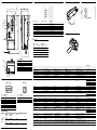
A Dimensional drawings
WI180C-PB
Supply voltage Tensión de alimentación
供电电压 供給電圧 Напряжение питания
12 – 24 VDC ± 10%
Power consumption Consumo de potencia
功耗 消費電力
Потребляемая мощность
2 W
Switch-on delay (WI180C-PB) Retardo de conexión (WI180C-PB)
开机反应时间(WI180C-PB) 起動遅延時間 (WI180C-PB)
Задержка включения (WI180C-PB) 500 ms
Switch-on delay (complete system) Retardo de conexión (sistema completo)
开机反应时间(整个系统) 起動遅延時間(システム全体)
Задержка включения (вся система) 2000 ms
Profile Perfil
侧面 Profil Профиль
Profibus DP-V1
Maximum number of modules Número máximo de módulos
最大模块连接数 最大モジュール数
Максимальное количество модулей
16
Transmission rates in kbps Velocidades de transmisión en kbit/s
传输速率(以kBit/s为单位) 伝送速度 [ kBit/s]
Скорость передачи данных, Кбит/с
9.6 / 19.2 / 45.45 / 93.75 / 187.5 / 500 /
1500 / 3000 / 6000 / 12,000
Maximum distance between nodes Distancia máxima entre nodos
节点间的最大距离(对应传输速率) ノード間の最大距離
Максимальное расстояние между
узлами
1200 m @ 9.6 – 93.75 kbps
1000 m @ 187.5 kbps
400 m @ 500 kbps
200 m @ 1500 kbps
100 m @ 3000 – 12,000 kbps
Process data Datos de proceso
过程数据 プロセスデータ
Параметры процесса
2x output, 1x input, 14 bits of received light
Asynchronous data Datos asíncronos
异步数据 非同期データ
Асинхронные данные
Fieldbus index map
Transmission interface Interfaz de transmisión
传输端口 伝送インターフェース Интерфейс передачи
RS-485
Power supply Fuente de alimentación
电源 供給電源 Напряжение питания
M8 plug connector, 4-pin
Additional interfaces Otras interfaces
其他端口 その他のインターフェース Прочие интерфейсы
Bus male connector, 5-pin, internal system
bus
D-Sub, 9-pin, Profibus
Noise immunity (length of cable ≤30 m) Insensibilidad al ruido (longitud del cable ≤ 30 m)
抗噪性能(连接线长度≤30 m) 耐ノイズ性(ケーブル長 ≤30 m) Помехоустойчивость (длина кабеля
≤ 30 м)
In accordance with EN 61000-6-2/EN
61131-2
Emissions Radiación
辐射 放射 Излучение
In accordance with EN 55011, Class A
Protection class Clase de protección
防护等级 保護クラス Класс защиты
3
Short-circuit protection Protección contra cortocircuito
短路保护 短絡保護 Стойкость к коротким замыканиям
In accordance with VDE 0160
Protection category Tipo de protección
防护类型 保護カテゴリー Категория защиты
IP50
Sensitivity to vibrations Insensibilidad a las vibraciones
抗震颤性能 耐振動性 Виброустойчивость
IEC 68, 10 – 55 Hz
Shock resistance Insensibilidad a los choques
抗冲击性能 耐衝撃性 Ударопрочность
IEC 68, 500 m/s² (~50 G)
Dimensions (HxWxD) in mm Medidas (Al x An x P) en mm
尺寸(长x宽x高)单位为mm 寸法(高さ×幅×奥行き) [mm] Размеры в мм (высота х ширина х
глубина)
39.2 x 102.55 x 39
Connections Conexiones
接口 接続 Соединения
M8, 4-pin, power supply
D-Sub, 9-pin, Profibus
Bus male connector, 5-pin, bus connector
Air humidity (operation/storage) Humedad del aire (servicio/almacenamiento)
空气湿度(工作/储存环境) 湿度(動作/保管) Влажность воздуха (эксплуатация/
хранение)
35 – 85% relative humidity
Temperature range (storage) Rango de temperatura (almacenamiento)
温度范围(储存环境) 温度範囲(保管) Диапазон температур (хранение)
-40 – +70 °C
Temperature range (operation, ≤ 3 connected
devices)
Rango de temperatura (servicio, ≤ 3 dispositivos
conectados)
温度范围(工作环境,至多3个连接设备) 温度範囲(動作、≤3 接続された機器) Диапазон температур (эксплуатация, ≤ 3
подключенных приборов)
-25 – +55 °C
Temperature range (operation, ≤ 8 connected
devices)
Rango de temperatura (servicio, ≤ 8 dispositivos
conectados)
温度范围(工作环境,至多8个连接设备) 温度範囲(動作、≤8 接続された機器) Диапазон температур (эксплуатация, ≤ 8
подключенных приборов)
-25 – +50 °C
Temperature range (operation, ≤ 16 connected
devices)
Rango de temperatura (servicio, ≤ 16 dispositivos
conectados)
温度范围(工作环境,至多16个连接设备) 温度範囲(動作、≤16 接続された機器) Диапазон температур (эксплуатация,
≤ 16 подключенных приборов)
-25 – +45 °C
B Connections
D Accessories
E Installation on DIN rail G Address switches
F Add a device
C LED display
39
25,3
27,1
92
102,55
38,2
33,2
18,835
37,9
10
10,4
No. Description
1 PWR-LED
2 RUN-LED
3 COM-LED
4 ERR-LED
5 x10 and x1 address switches
6 M8 power connection, 4-pin
7 Bus male connector, 5-pin
8 Profibus connection, D-Sub, 9-pin
Probus (D-Sub, 9-Pin)
12345
6789
Pin Description
1 Not assigned
2 Not assigned
3 RxD+/TxD+
4 RTS
5 DGND
6 +5 VDC
7 Not assigned
8 RxD-/TxD-
9 Not assigned
Power (M8, 4-Pin)
Pin Description
1 +12–24 VDC
2 Not assigned
3 GND
4 Not assigned
4
2
1 3
PWR RUN COM ERR Description
– – – – No power supply
X – – – Power supply established, device initialized
X X – – Initialization completed
X X X – Communication established with DP master, function free of errors
X Flashes acyclically –/X X/Flashes acyclically No communication with bus devices or fatal error
X –(100 ms) –/X X/Flashes acyclically Error present
X –/Flashes acyclically –/X X Incorrect configuration
X –/Flashes cyclically –/X Flashes acyclically Configuration not completed
X –/X – Flashes cyclically No communication with DP master
Part No. Type Description
6009870 D0L-0804-G02M Female, M8, 4-pin, straight,
2 m cable
6009872 D0L-0804-G05M Female, M8, 4-pin, straight,
5 m cable
6009871 D0L-0804-W02M Female, M8, 4-pin, angled, 2 m
cable
6009873 D0L-0804-W05M Female, M8, 4-pin, angled, 5 m
cable
5313011 BF-EB01-W190 Rail end cap for block mounting
UL Satisfaction Ratings
Power input Power output Connected device quantity Maximum surrounding air temperature
12 ... 30 VDC
max. 0.45 A
Class 2
connect up to
3 devices
50 °C
12 ... 30 VDC
max. 1.28 A
Class 2
12 ... 30 VDC
max. 0.8 A
Class 2
connect up to
8 devices
50 °C
12 ... 30 VDC
max. 1.12 A
Class 2
connect up to
16 devices
45 °C
-
 1
1
-
 2
2
-
 3
3
-
 4
4


SICK WI180C-PB Profibus-Koppler Quickstart
- Tipo
- Quickstart
em outros idiomas
- español: SICK WI180C-PB Profibus-Koppler
- français: SICK WI180C-PB Profibus-Koppler
- italiano: SICK WI180C-PB Profibus-Koppler
- 日本語: SICK WI180C-PB Profibus-Koppler
Artigos relacionados
-
SICK WI180C-B404 Instruções de operação
-
-
-
-
SICK WLL180T Instruções de operação
-
-
-
-