Ingersoll-Rand ENL 2 Instructions For Installation And Operation Manual
- Tipo
- Instructions For Installation And Operation Manual

Save These Instructions
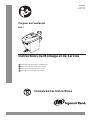
Instructions for Installation
and Operation
Instruções de instalação e de serviço
PT
Instructions de montage et de service
FR
Instruciones de instalación y de servicio
ES
Instructions for Installation and Operation
EN
80442866
Revision B
October 2014
Condensate Drain
ENL 2
PRINT LANGUAGE
ENGLISH
PORTUGUESE
SPANISH
FRENCH
01-2680

EN
2 ingersollrandproducts.com 80442866
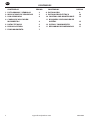
CONTENTS
CONTENTS PAGE
1. PICTOGRAMS AND SYMBOLS 3
2. SAFETY INSTRUCTIONS 3
3. PROPER USE 4
4. EXCLUSION FROM THE SCOPE OF
APPLICATION 4
5. TECHNICAL DATA 5
6. DIMENSION DRAWING 6
7. FUNCTION 7
CONTENTS PAGE
8. INSTALLATION 8
9. ELECTRICAL INSTALLATION 10
10. CONTROL AND MAINTENANCE 12
11. TROUBLESHOOTING AND FAULT
ELIMINATION 15
12. ELEMENTS AND COMPONENTS 16
13. RECOMMENDED SPARE PARTS 17

80442866 ingersollrandproducts.com 3
EN
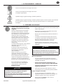
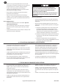
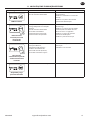
1. PICTOGRAMS AND SYMBOLS
Observe the installation and operating instructions
Observe the installation and operating instructions
(on the type plate)
General danger symbol (danger, warning, caution)
General danger symbol (danger, warning, caution) for supply voltage and supply voltage carrying
plants components
2. SAFETY INSTRUCTIONS
Please check whether or not these
instructions correspond to the device
type.
Adhere to all advice given in these
operating instructions. They include
essential information which must
be observed during the installation,
operation and maintenance. Therefore it is
imperative for the service technician and
the responsible operator / technical sta
to read these operating instructions prior
to installation, start-up and maintenance.
The operating instructions must be
accessible at any time at the place of
application of the ENL 2.
In addition to these operating instructions,
local or national regulations must be
complied with, if necessary.
Make sure that the ENL 2 is operated
only within the permissible limit values
indicated on the ID plate. Any deviation
involves a risk for persons and materials,
and may result in malfunction and service
failures.
If you have any queries regarding these
installation- and operating instructions,
please contact INGERSOLL RAND.
DANGER
Compressed air!
Risk of serious injury or death through contact
with quickly or suddenly escaping compressed air
or through bursting plant components or plant
components which are not secured.
Measures:
Do not exceed the maximum operating pressure (see
type plate).
Only carry out service measures when the system is
pressure less.
•
•
Use pressure-resistant installation material only.
The feed pipe must be tubed rmly. Discharge pipe:
short, xed pressure hose onto pressure-resistant pipe.
Make sure that persons or objects cannot be hit by
condensate or escaping compressed
DANGER
Supply voltage!
There is the risk of an electric shock involving injury or
death when coming into contact with
non- insulated components carrying supply voltage.
Measures:
During electric installations, all regulations in force
need to be adhered to (e.g. VDE 0100 / IEC 60364).
Service measures must only be undertaken when
the system is deactivated.
The removed control unit has no IP degree of
protection.
All types of electrical works must be carried out by
authorized and qualied personnel only.
Further safety instructions:
For installation and operation, the national regulations
and safety codes in force must also be adhered to.
Do not use the ENL 2 in hazardous areas.
Regarding the inlet screw joints, excessive tightening
forces must be avoided. This applies in particular to
conical screw joints.
The ENL 2 will only function when voltage is applied.
Do not use the test button for permanent drainage.
Use genuine spare parts only. This is imperative to
ensure perfect functioning.
•
•
•
•
•
•
•
•
•
•
•
•
•

4 ingersollrandproducts.com 80442866
EN
Additional advice:
The removed control unit has no IP degree of
protection.
During installation, use spanner at at the feed pipe
(wrench size SW27) as a back rest.
The service unit must not be dismantled.
CAUTION
Malfunction during operation!
Through incorrect installation and poor maintenance,
malfunction may occur at the ENL 2.
Condensate which is not discharged may cause
damage to plants and in production processes.
•
•
•
Measures:
Condensate drainage which is reliable in performance
directly optimizes the compressed-air quality.
To prevent damage and breakdowns, it is imperative
to observe the following:
Exact compliance with the specications of use
and with the performance parameters of the
ENL 2, in connection with the case of application
(see “Proper use” section)
Exact compliance with the installation- and
operation instructions in this manual
Regular maintenance and control of the ENL 2 in
accordance with the instructions in this operating
manual.
•
•
a.
b.
c.
d.
3. PROPER USE
The ENL 2 is an electronically level-controlled
condensate drain for compressed-air plants.
The device is employed within the permissible
performance parameters (see “Technical data”).
The ENL 2 is able to drain condensate under operating
pressure from the plant components virtually without
compressed-air loss.
For its function, the ENL 2 requires an supply voltage
and an operating pressure (see “Technical data”).
•
•
•
•
As far as the employment in plants with increased
demands on compressed air is concerned (food
industry, medical technology, laboratory equipment,
special processes etc.), the operator must decide on
measures for the monitoring of the compressed-air
quality. These have an eect on the safety of the
subsequent processes and may prevent damage to
persons and plants.
It is the task of the operator to ensure that the
indicated conditions are met during the entire
operating time.
•
•
4. EXCLUSION FROM THE SCOPE OF APPLICATION
The ENL 2 as a condensate drain alone cannot
guarantee a dened compressed-air quality, for
this purpose, other additional technical devices are
required.
ENL 2 is not suitable for use in plants carrying vacuum
or atmospheric ambient pressure or in ex-areas.
ENL 2 must not be exposed to permanent direct solar
or thermal radiation.
•
•
•
ENL 2 must not be installed and operated in areas with
an aggressive atmosphere.
The ENL 2 is not heatable and, therefore, not suitable
for the use in areas where frost is likely to occur.
The ENL 2 is not suitable for CO2 plants.
•
•
•

80442866 ingersollrandproducts.com 5
EN
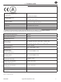
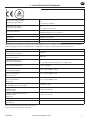
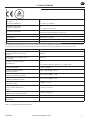
min./max. operating pressure
(see type plate)
0,8...16 bar (12...230 psi)
or
1,2...16 bar (17...230 psi)
min./max. temperature
(see type plate)
+1...+60 °C (+34...+140 °F)
or
+1...+70 °C (+34...+158 °F)
Condensate inow
NPT ½ (½”) internal
max. screw-in depth 13,5 mm (½”)
Condensate outow G ¼ (¼”) Ø 8 ... 10 mm hose connector
Condensate oil-contaminated + oil-free
Housing aluminium + plastic, glass bre-reinforced
Weight (empty) 0,8 kg (1.8 lbs)
This product has been tested to the requirements of CAN/CSA-C22.2 No. 61010-1-12, third edition, including
a later version of the same standard incorporation the same level of testing requirements.
Peak compressor performance 100 scfm
Peak refrig. dryer performance
(only with pre-separation)
200 scfm
Peak lter performance
(behind dryer)
1000 scfm
Supply voltage
(see type plate)
95…240 VAC ±10% (50…60 Hz) /100…125 VDC ±10%
or
24…48 VAC ±10% (50…60 Hz) / 18…72 VDC ±10%
Power consumption P = 0,6 ... 3 VA (W)
Recommended
cable-jacket diameter
Ø 5,0…10 mm (0,20“…0,39“)
Recommended
wire cross-section
Spring-loaded terminal
0,75...1,5 mm² (AWG 16...20)
Recommended
wire cross-section
Screw terminal
0,75...2,5 mm² (AWG 14...20)
Recommended
stripping of cable jacket
~ 50 mm (~ 1.97”)
Recommended
length of the wire end tube
Spring-loaded terminal
~ 8 mm (~ 0.31 inch)
Recommended
length of the wire end tube
Screw terminal
~ 6 mm (~ 0.24 inch)
Protection class IP 67
Overvoltage category
(IEC 61010-1)
II
VAC = V alternating current
VDC = V direct current
5. TECHNICAL DATA

6 ingersollrandproducts.com 80442866
EN
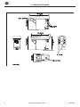
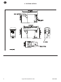
6. DIMENSION DRAWING

80442866 ingersollrandproducts.com 7
EN
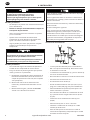
7. FUNCTION
Via the inlet line (1) the condensate ows into the
ENL 2 and accumulates in the housing
(2).
A capacitive functioning sensor (3) continuously registers
the lling level and relays a signal to the electronic
control as soon as the container is lled.
The pilot valve (4) is activated and the membrane (5)
opens the outlet line to discharge the condensate (6).
When the ENL 2 is empty, the outlet line is reclosed
tightly in time before unnecessary compressedair
losses occur.
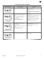
When applying supply voltage, the ENL 2 carries out a
self-test.
The LED is lit orange for 1 second; subsequently, the
device changes over to the “ready-to-operate” state
and the LED is lit green.
Ready to operate, voltage is applied.
Test of the valve function (manual drainage):
Press and hold the push-button for approx. 2 s.
Do not use for permanent drainage.

8 ingersollrandproducts.com 80442866
EN
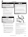
8. INSTALLATION
DANGER
Compressed air!
Risk of serious injury or death through contact
with quickly or suddenly escaping compressed air
or through bursting plant components or plant
components which are not secured.
Measures:
Do not exceed the maximum operating pressure (see
type plate).
Only carry out service measures when the system is
pressure less.
Use pressure-resistant installation material only.
The feed pipe must be tubed rmly. Discharge pipe:
short, xed pressure hose onto pressure-resistant pipe.
Make sure that persons or objects cannot be hit by
condensate or escaping compressed air.
CAUTION
Malfunction during operation!
Through incorrect installation and poor maintenance,
malfunction may occur at the ENL 2.
Condensate which is not discharged may cause
damage to plants and in production processes.
Measures:
Condensate drainage which is reliable in performance
directly optimizes the compressed-air quality.
To prevent damage and breakdowns, it is imperative
to observe the following:
Exact compliance with the specications of use
and with the performance parameters of the ENL
2, in connection with the case of application (see
“Proper use” section)
Exact compliance with the installation- and
operation instructions in this manual
Regular maintenance and control of the ENL 2 in
accordance with the instructions in this operating
manual.
•
•
•
•
•
•
•
a.
b.
c.
NOTE
It is imperative to observe all hazard statements and
warnings listed here.
Please also observe all regulations and notes regarding
industrial safety and re prevention at the place of
installation.
As a matter of principle, only use suitable and appropriate
tools and materials in a proper condition.
Do not use aggressive cleaners and improper devices such
as high-pressure cleaners.
Please note that condensates may contain aggressive or
harmful components. Therefore, skin contact should be
avoided.
Condensate is subject to mandatory waste disposal. As
such, it must be collected in suitable containers, and
disposed of or processed properly.
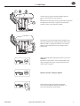
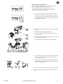
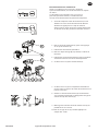
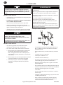
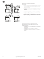
Installation instructions:
Only the displayed installation position of the ENL 2 (3)
is permissible. Never install in a horizontal or any other
tilted position.
Feed pipe (1) and ball valve (2) at least G½.
No lter or screen in the inlet line.
Slope in the inlet line >1%.
Use ball valves (2) only.
Operating pressure: min. 0,8/1,2 bar (12/17 psig), max.
16 bar (230 psig). See type plate.
Short pressure hose (4) xed on a pressureresistant
pipe.
The required minimum pressure increases by 0,1 bar
(1,4 psi) per metre gradient in the discharge pipe (5).
Discharge pipe (5) rising by max. 5 m (16,4ft).
Install manifold (6) ½” with a slope of 1%.
Introduce the discharge pipe (5) from the top into the
manifold (6).
1SJPSUPUIFTUBSUVQBMXBZTDBSSZPVUBMFBLUFTUBOE
WFSJGZUIFDPSSFDUFOHBHFNFOUPGUIFDPOUSPMVOJU
•
•
•
•
•
•
•
•
•
•
•
t

80442866 ingersollrandproducts.com 9
EN
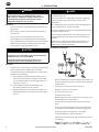
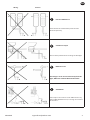
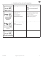
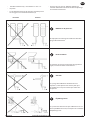
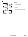
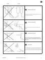
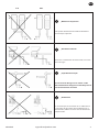
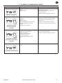
Wrong Correct
Pressure dierences!
Each condensate accumulation point must be
drained separately.
Continuous slope!
Avoid a water pocket when installing the feed pipe
Deector area!
If drainage is to be carried out directly from the
pipe, deection of the air ow will be useful.
Ventilation!
If the slope in the inlet line is not sucient or if any
other inow problems occur, a venting line needs to
be installed.

10 ingersollrandproducts.com 80442866
EN
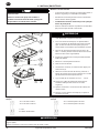
9. ELECTRICAL INSTALLATION
DANGER
Supply voltage!
There is the risk of an electric shock involving injury or
death when coming into contact with non-insulated
components carrying supply voltage.
Measures:
During electric installations, all regulations in force
need to be adhered to (e.g. VDE 0100 / IEC 60364).
Service measures must only be undertaken when the
system is deactivated.
The removed control unit has no IP degree of
protection.
All types of electrical works must be carried out by
authorized and qualied personnel only.
•
•
•
•
NOTE
Read the permissible supply voltage on the type
plate and make sure this voltage is observed.
For the supply voltage, a reliably accessible
separator must be provided close-by (e.g. power
plug or switch), which separates all current-carrying
conductors.
At a low-voltage supply
(< 50 VAC / < 75 VDC), only use a prot
ective
extralow- voltage (PELV).
Carry out installation in accordance with
VDE 0100 / IEC 60364.
Observe the terminal assignment.
Do not install when the devic
e is energized.
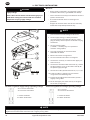
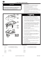
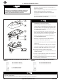
Unscrew the screws (1) and remove the upper part
of the cover (2).
Unscrew the threaded cable connection (3), remove
the plug (if there is one), and lead the cable (4) f
or
the power supply through.
Connect the cable (4) with terminals X1 (1.1, 1.2) (5).
Install the cables as shown (see also terminal
assig
nment in the following text).
Tighten the threaded cable connection (3) with a
slightly sealing eec
t.
Put on the upper part of the cover (2) and tighten
the screws (1) ngertight.
1.
2.
3.
4.
5.
6.
7.
8.
9.
10.
11.
12.
Terminal assignment supply voltage (operating voltage)
• X 1.1 L mains connection
• X 1.2 N mains connection
L = Outer conductor
N = Outer conductorw
Terminal assignment low voltage (operating voltage)
• X 1.1 L mains s
• X 1.2 N mains connection
L = Outer conductor
N = Outer conductor
NOTE
At a low voltage supply (< 50 VAC / < 75 VDC), only use a protective extra-low-voltage (PELV).
Tighten the threaded cable connection with a slightly sealing eect.

80442866 ingersollrandproducts.com 11
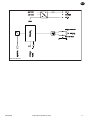
EN
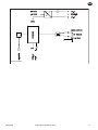
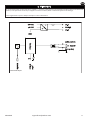
Electric diagram

12 ingersollrandproducts.com 80442866
EN
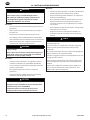
10. CONTROL AND MAINTENANCE
DANGER
Compressed air!
Risk of serious injury or death through contact
with quickly or suddenly escaping compressed air
or through bursting plant components or plant
components which are not secured.
Measures:
Do not exceed the maximum operating pressure (see
type plate).
Only carry out service measures when the system is
pressure less.
Use pressure-resistant installation material only.
The feed pipe must be tubed rmly. Discharge pipe:
short, xed pressure hose onto pressure-resistant pipe.
Make sure that persons or objects cannot be hit by
condensate or escaping compressed air.
DANGER
Supply voltage!
There is the risk of an electric shock involving injury or
death when coming into contact with non-insulated
components carrying supply voltage.
Measures:
During electric installations, all regulations in force
need to be adhered to (e.g. VDE 0100 / IEC 60364).
Service measures must only be undertaken when the
system is deactivated.
The removed control unit has no IP degree of
protection.
All types of electrical works must be carried out by
authorized and qualied personnel only.
CAUTION
Malfunction during operation!
Through incorrect installation and poor maintenance,
malfunction may occur at the ENL 2.
Condensate which is not discharged may cause
damage to plants and in production processes.
•
•
•
•
•
•
•
•
•
Measures:
Condensate drainage which is reliable in performance
directly optimizes the compressed-air quality.
To prevent damage and breakdowns, it is imperative
to observe the following:
Exact compliance with the specications of use and
with the performance parameters of the ENL 2, in
connection with the case of application (see “Proper
use” section)
Exact compliance with the installation- and operation
instructions in this manual
Regular maintenance and control of the ENL 2 in
accordance with the instructions in this operating
manual.
NOTE
It is imperative to observe all hazard statements and
warnings listed here.
Please also observe all regulations and notes regarding
industrial safety and re prevention at the place of
installation.
As a matter of principle, only use suitable and appropriate
tools and materials in a proper condition.
Do not use aggressive cleaners and improper devices such
as high-pressure cleaners.
Please note that condensates may contain aggressive or
harmful components. Therefore, skin contact should be
avoided.
Condensate is subject to mandatory waste disposal. As
such, it must be collected in suitable containers, and
disposed of or processed properly.
•
•
•
•
•

80442866 ingersollrandproducts.com 13
EN
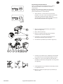
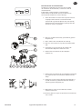
Maintenance recommendation:
After 2 x 8,760 operating hours or one million switching
cycles, a maintenance message is released.
The green power LED ashes. Afterwards, or at the
latest after two years (2 x 8,760 operating hours), the
service unit (5) needs to be replaced.
Prior to the replacement of the service unit, a reset
needs to be carried out. The control unit is released
by actuating the arresting hook. When removed, the
TEST button below the LED must be pressed and held
for at least ve seconds.
Remove the control unit (1) by pressing the arresting
hook (2).
Unfasten the ENL 2 from the outlet (3).
Remove the design shell (4) (if there is one) usinga
screwdriver (10).
Detach the service unit (5) from the tubing at the inlet
by removing the union nut.
or remove the screws (6) from the angle nozzle (7).
or remove the screws (8) at the intermediate adapter
(9) and remove the latter from the service unit by
pulling it downwards.
Check whether or not the new service unit (5) goes
with the control unit (1) (model designation and color
of the arresting hook (2)).
Installation of the new service unit (5) in reverse order.
Please consider the torque for the screws (8) with 4...5
Nm.
1.
2.
3.
4.
5.
6.
7.
8.
9.
10.

14 ingersollrandproducts.com 80442866
EN
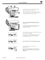
Installation of the control unit on the service unit:
Check whether or not the service unit (5) goes with
the control unit (1) (model designation and color of
the arresting hook).
Check whether or not the sealing mat (11) and the
contact springs (13) are clean, dry, and free from
impurities.
Introduce the sensor (12) into the sensor tube plate
(14).
Hang the hook (15) of the control unit (1) in the
sensor tube plate (14).
Press the control unit (1) against the service unit (5)
and snap into place.
1.
2.
3.
4.
5.
Start-up subsequent to maintenance measures:
Always carry out prior to the start-up:
Leak test of the screwed connector
Check of the electrical connections
Check of the correct engagement of the control unit
•
•
•

80442866 ingersollrandproducts.com 15
EN
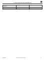
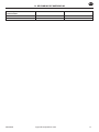
11. TROUBLESHOOTING AND FAULT ELIMINATION
Symptoms Possible reasons Measures
LED does not light up
Supply voltage incorrect
Circuit board defective
Check voltage on the type plate
Check the connections and the supply
voltage
Check the circuit boards for possible
damage
Test button pressed,
but no condensate
discharge
Feed pipe and/or discharge pipe
blocked or obstructed
Wear and tear
Circuit board defective
Service unit defective
Minimum pressure not reached
Maximum pressure exceeded
Check feed and discharge pipe
Check whether or not the valve opens
audibly (press the test button several
times for > 2 seconds)
Check the circuit board for possible
damage
Check the operating pressure
Condensate discharge
only when the test button
is pressed
Feed pipe without sucient slope
Cross section not large enough
Condensate accumulation too high
(surge)
Service unit extremely dirty
Install feed pipe with a slope
Replace the service unit
Device blows o continuously
Service unit defective or dirty Replace the service unit

16 ingersollrandproducts.com 80442866
EN
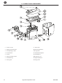
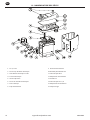
12. ELEMENTS AND COMPONENTS
Screw 3.5 x 10
Upper part of the cover
Cord packing 2 x 307
Circuit board
Sensor
Lower part of the cover
Cable bushing
Sealing mat
1.
2.
3.
4.
5.
6.
7.
8.
Service unit
Hose connector G¼
O-ring 20 x 2
Intermediate adapter
Screw M6 x 12
O-ring 14 x 1.78
Angle adapter G½
Design shell
9.
10.
11.
12.
13.
14.
15.
16.

80442866 ingersollrandproducts.com 17
EN
13. RECOMMENDED SPARE PARTS
Available sets of spare parts Contents Order number
Service-Unit 9 38446100

__________________________________________________________________________________________________________________________________________________________________
QUOTATIONS SUBJECT TO CHANGE WITHOUT PRIOR NOTICE - ALL AGREEMENTS CONTINGENT UPON STRIKES, ACCIDENTS AND OTHER CONDITIONS BEYOND OUR CONTROL.
ALL CONTRACTS ARE SUBJECT TO APPROVAL BY AN OFFICER OF THE COMPANY.
REGISTERED IN IRELAND No. 349511. REGISTERED OFFICE: 170/175 LAKEVIEW DRIVE, AIRSIDE BUSINESS PARK SWORDS CO DUBLIN IRELAND.
EC Declaration of Conformity
We Ingersoll Rand declare under our responsibility, that the products listed below, have been designed to
comply with the relevant sections of the referenced standards. The unit as supplied complies with all
applicable essential requirements of these Directives.
Description of Product: Condensate Drain
Type: ENL 2 …, ENL 5…, ENL 10 …
Voltage Options: 95 ….240 VAC +/- 10% (50 ... 60 Hz)
100 … 125 VDC +/- 10%
Pressure Options: 1.2 – 16 bar (g)
niard etasnednoC :noitcnuf dna noitpircsed tcudorP for the electronically level
Controlled discharge of condensate in the
Compressed Air System.
Low Voltage Directive 2006/95/EC
Harmonised standards applied: EN 61010 – 1: 2010
Year of CE labelling 14
EMC- Directive 2004/108/EC
Harmonised standards applied: EN61326-1:2006
EN55011:2009 + A1:2010, Group 1, Class B
RoHS Directive 2011/65 EU
The stipulations of the 2011/65 EU on the restriction of the use of certain hazardous substances in electrical
and electronic equipment are observed.
David Isherwood (Quality Manager).
Date: 14
th
August 2014.
COMPRESSED AIR SOLUTIONS
170/175 Lakeview Drive
Airside Business Park
Swords, Co. Dublin
Ireland
Tel: +353 1 870 7000
http://www.ingersoll-rand.com


ingersollrandproducts.com
© 2014 Ingersoll-Rand
A página está carregando...
A página está carregando...
A página está carregando...
A página está carregando...
A página está carregando...
A página está carregando...
A página está carregando...
A página está carregando...
A página está carregando...
A página está carregando...
A página está carregando...
A página está carregando...
A página está carregando...
A página está carregando...
A página está carregando...
A página está carregando...
A página está carregando...
A página está carregando...
A página está carregando...
A página está carregando...
A página está carregando...
A página está carregando...
A página está carregando...
A página está carregando...
A página está carregando...
A página está carregando...
A página está carregando...
A página está carregando...
A página está carregando...
A página está carregando...
A página está carregando...
A página está carregando...
A página está carregando...
A página está carregando...
A página está carregando...
A página está carregando...
A página está carregando...
A página está carregando...
A página está carregando...
A página está carregando...
A página está carregando...
A página está carregando...
A página está carregando...
A página está carregando...
A página está carregando...
A página está carregando...
A página está carregando...
A página está carregando...
A página está carregando...
A página está carregando...
A página está carregando...
A página está carregando...
A página está carregando...
A página está carregando...
A página está carregando...
A página está carregando...
A página está carregando...
A página está carregando...
A página está carregando...
A página está carregando...
-
 1
1
-
 2
2
-
 3
3
-
 4
4
-
 5
5
-
 6
6
-
 7
7
-
 8
8
-
 9
9
-
 10
10
-
 11
11
-
 12
12
-
 13
13
-
 14
14
-
 15
15
-
 16
16
-
 17
17
-
 18
18
-
 19
19
-
 20
20
-
 21
21
-
 22
22
-
 23
23
-
 24
24
-
 25
25
-
 26
26
-
 27
27
-
 28
28
-
 29
29
-
 30
30
-
 31
31
-
 32
32
-
 33
33
-
 34
34
-
 35
35
-
 36
36
-
 37
37
-
 38
38
-
 39
39
-
 40
40
-
 41
41
-
 42
42
-
 43
43
-
 44
44
-
 45
45
-
 46
46
-
 47
47
-
 48
48
-
 49
49
-
 50
50
-
 51
51
-
 52
52
-
 53
53
-
 54
54
-
 55
55
-
 56
56
-
 57
57
-
 58
58
-
 59
59
-
 60
60
-
 61
61
-
 62
62
-
 63
63
-
 64
64
-
 65
65
-
 66
66
-
 67
67
-
 68
68
-
 69
69
-
 70
70
-
 71
71
-
 72
72
-
 73
73
-
 74
74
-
 75
75
-
 76
76
-
 77
77
-
 78
78
-
 79
79
-
 80
80


Ingersoll-Rand ENL 2 Instructions For Installation And Operation Manual
- Tipo
- Instructions For Installation And Operation Manual
em outras línguas
- español: Ingersoll-Rand ENL 2
- français: Ingersoll-Rand ENL 2
- English: Ingersoll-Rand ENL 2
Artigos relacionados
-
Ingersoll-Rand ENL 10 Instructions For Installation And Operation Manual
-
-
-
-
-
-
-
-