Ingersoll-Rand R37-160 Product Maintenance Information
- Tipo
- Product Maintenance Information

80446354
Revision D
November 2014
Save These Instructions
Contact-Cooled Rotary Screw Air Compressor
Product Maintenance Information
R37-160
121714.07.03
PRINT LANGUAGE
ENGLISH
SPANISH
FRENCH
PORTUGUESE

EN
80446354 Rev D EN-2
ABOUT THIS MANUAL . . . . . . . . . . . . . . . . . . . . . . . . . . . . . . . . . . . . . .2
PERSONNEL . . . . . . . . . . . . . . . . . . . . . . . . . . . . . . . . . . . . . . . . . . . . . . . .2
SAFETY . . . . . . . . . . . . . . . . . . . . . . . . . . . . . . . . . . . . . . . . . . . . . . . . . . . .2
AIR COMPRESSOR MAINTENANCE. . . . . . . . . . . . . . . . . . . . . . . . . . .3
Maintenance Prompts . . . . . . . . . . . . . . . . . . . . . . . . . . . . . . . . . . . .3
Maintenance Chart. . . . . . . . . . . . . . . . . . . . . . . . . . . . . . . . . . . . . . .3
Routine Maintenance . . . . . . . . . . . . . . . . . . . . . . . . . . . . . . . . . . . . .4
Checking Coolant Level . . . . . . . . . . . . . . . . . . . . . . . . . . . . . . . . . . . . . . . . 4
Adding Coolant . . . . . . . . . . . . . . . . . . . . . . . . . . . . . . . . . . . . . . . . . . . . . . . 4
Draining Coolant . . . . . . . . . . . . . . . . . . . . . . . . . . . . . . . . . . . . . . . . . . . . . . 4
Analyzing Food-Grade Coolant . . . . . . . . . . . . . . . . . . . . . . . . . . . . . . . . 4
Sampling Coolant . . . . . . . . . . . . . . . . . . . . . . . . . . . . . . . . . . . . . . . . . . . . . 4
Changing Coolant Filter. . . . . . . . . . . . . . . . . . . . . . . . . . . . . . . . . . . . . . . . 5
Checking Separator Element . . . . . . . . . . . . . . . . . . . . . . . . . . . . . . . . . . . 5
Changing Separator Element. . . . . . . . . . . . . . . . . . . . . . . . . . . . . . . . . . . 5
Inspecting Separator Tank / Pressure System . . . . . . . . . . . . . . . . . . . . 5
Cleaning / Checking Scavenge Screen. . . . . . . . . . . . . . . . . . . . . . . . . . . 6
Replacing Coolant Hoses. . . . . . . . . . . . . . . . . . . . . . . . . . . . . . . . . . . . . . . 6
Checking Minimum Pressure Check Valve (MPCV) . . . . . . . . . . . . . . . 6
Changing Air Filter . . . . . . . . . . . . . . . . . . . . . . . . . . . . . . . . . . . . . . . . . . . . 6
Regreasing Motor . . . . . . . . . . . . . . . . . . . . . . . . . . . . . . . . . . . . . . . . . . . . . 6
Cleaning Air Cooled Sequential Cooling System . . . . . . . . . . . . . . . . . 6
Removing / Installing Air Cooled Cooler. . . . . . . . . . . . . . . . . . . . . . . . . 6
Cleaning Water Cooled Cooler (for both Clean & Harsh
Water Options) . . . . . . . . . . . . . . . . . . . . . . . . . . . . . . . . . . . . . . . . . . . . . . . . 7
Checking High Airend Temperature Sensor. . . . . . . . . . . . . . . . . . . . . . 7
Cleaning Motor Cowl . . . . . . . . . . . . . . . . . . . . . . . . . . . . . . . . . . . . . . . . . . 7
Removing / Replacing Starter Box Power Drive Module (PDM) Filter
Element (For VSD only) . . . . . . . . . . . . . . . . . . . . . . . . . . . . . . . . . . . . . . . . 7
Cleaning / Checking Condensate Drain. . . . . . . . . . . . . . . . . . . . . . . . . . 8
Cleaning / Installing Package Pre-Filter . . . . . . . . . . . . . . . . . . . . . . . . . 8
Checking / Cleaning No Loss Drain Trap (where tted) . . . . . . . . . . . 8
Monitoring Fluid and Performing Shock Pulse Bearing Analysis . . 8
TROUBLESHOOTING. . . . . . . . . . . . . . . . . . . . . . . . . . . . . . . . . . . . . . . .9
R3775 INTEGRATED DRYER MAINTENANCE . . . . . . . . . . . . . . . 13
Maintenance Chart. . . . . . . . . . . . . . . . . . . . . . . . . . . . . . . . . . . . . 13
Cleaning Condensate Drains (Timed Drains Only). . . . . . . . . . . . . . . 13
Testing Condensate Drains (No-Loss Drains Only). . . . . . . . . . . . . . . 13
Troubleshooting Condensate Drains (Electronic
Drains Only) . . . . . . . . . . . . . . . . . . . . . . . . . . . . . . . . . . . . . . . . . . 13
Disassembling the Integrated Dryer. . . . . . . . . . . . . . . . . . . . . . . . 13
Decommissioning the Integrated Dryer . . . . . . . . . . . . . . . . . . . . . 13
CONTENTS
ABOUT THIS MANUAL
PERSONNEL
SAFETY
Proper use, inspections and maintenance increases the life and usefulness
of the compressor. It is extremely important that anyone involved with
maintaining the compressor be familiar with the servicing procedures of
these compressors and be physically capable of conducting the procedures.
These personnel shall have skills that include:
1. Proper and safe use and application of mechanics common hand
tools as well as special Ingersoll Rand or recommended tools.
2. Safety procedures, precautions and work habits established by
accepted industry standards.
Some maintenance procedures are technical in nature and require
specialized tools, equipment, training and experience to accomplish
correctly. In such situations, only allow Ingersoll Rand trained technicians
to perform maintenance on this compressor. Service or inspections beyond
the procedures given in this manual shall not be attempted by operating
personnel.
For additional information contact the Ingersoll Rand factory or the nearest
service provider.
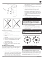
Before undertaking any work on the compressor, ensure that the electrical
supply has been isolated, locked o, tagged and the compressor has been
relieved of all pressure. Ensure the compressor is electrically isolated for at
least 15 minutes before commencing any maintenance work. See the Product
Safety Information manual for additional information.
Ingersoll Rand cannot know of or provide all the procedures by which
repairs may be conducted and the hazards and/or results of each method. If
maintenance procedures not specically recommended by the manufacturer
are conducted, ensure that safety is not endangered by the actions taken.
If you are unsure of a maintenance procedure or step, place the compressor
in a safe condition before consulting technical assistance.
The use of other than genuine Ingersoll Rand replacement parts may result
in safety hazards, decreased performance and increased maintenance and
may invalidate all warranties.
For additional information contact the Ingersoll Rand factory or the nearest
service provider.
The purpose of this manual is to provide maintenance and troubleshooting guidelines for the compressor.
For supporting documentation refer to Table 1.
Table 1: Product Manuals
Publication Product
Part/Document Number by Region
Americas EMEA * Asia Pacic
Product Safety Information Manual All 80446313 80446156 80446321
Product Information Manual All 80446339 80446164 80446347
Product Parts Information Manual
R37-45 kW 80448095
R55-75 kW 80446271
R132-160 kW Single-Stage 80446057
R90-160 kW Two-Stage 80446065
* Europe, Middle East and Africa
Product specication sheets and reference drawings are also available.
121714.07.03

EN-3 80446354 Rev D
EN
AIR COMPRESSOR MAINTENANCE
Maintenance Prompts
The service warning and ashing LED will appear at intervals dependent
on the service level selected. Refer to the Product Information manual for
information about service level settings.
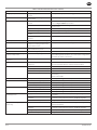
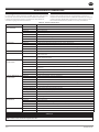
Maintenance Chart
Maintenance should be performed per the recommendations below in the
following priority: (1) Perform maintenance when indicated by the controller;
(2) Perform maintenance through either hourly intervals or scheduled
maintenance intervals, or (3) Annually.
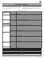
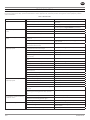
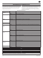
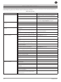
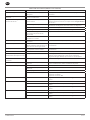
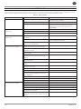
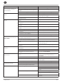
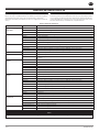
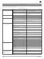
Table 2: Maintenance Chart
Period Action Maintenance Item
When indicated by
controller
Replace Air lter element
Replace Coolant lter element
Replace Separator element
Daily Check Connections and hoses for leaks
Check Coolant level
Check Condensate drain operation
Check Controller for service indicators
Check Package pre-lter for blockage
Monthly Inspect Air-cooled sequential cooling system for blockage
Inspect Water-cooled sequential cooling system screens
Inspect Starter box power drive module (PDM) lter element
Analysis Water from water-cooled sequential cooling system
Every 500 hours Analysis Food-grade coolant
Every 1000 hours Replace Food-grade coolant (if not using food-grade lter module)
Replace Food-grade coolant lter (if not using food-grade lter module)
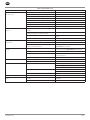
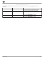
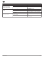
Every 2000 hours or
3 months
Inspect Air lter element
Inspect Coolant lter element
Inspect Starter box power drive module (PDM) lter element
Replace Food-grade coolant (if using food-grade lter module)
Replace Food-grade lter module
Analysis Shock pulse bearing
Analysis Coolant
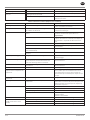
Every 4000 hours or
6 months
Inspect Scavenge screen for blockage
Replace Air lter element
Replace Coolant lter element
Replace Starter box power drive module (PDM) lter element
Replace Package pre-lter element
Clean Air-cooled sequential cooling system
Inspect / Clean Water-cooled sequential cooling system
Grease
All motors (as required)
Calibrate Pressure transducers
Analysis Coolant
Analysis Shock pulse bearing
Every 8000 hours or
annually
Replace Standard coolant [8000 hours or every 2 years]
Replace Separator element
Replace No-loss condensate drain service module
Service Minimum pressure check valve (MPCV) service kit
Service Inlet valve service kit
16000 hours Replace Coolant hoses
Replace Contact tips
NOTICE
Inspect and replace coolant lter elements and separator elements more frequently in dirty operating environments.
NOTICE
Read the motor data plate(s) or call the motor manufacturer(s) to determine specic greasing requirements. For motors that require greasing,
grease them more frequently in harsh environments or higher ambient conditions.
121714.07.03

EN
80446354 Rev D EN-4
Routine Maintenance
This section refers to the various components which require periodic
maintenance and replacement.
Refer to safety information and maintenance procedures prior to carrying out
any of the maintenance in the following sections.
Checking Coolant Level
The coolant level should be checked daily. A coolant level sight glass is
located on the side of the separator tank. While the compressor is running
under load, coolant should always be visible in the sight glass. The normal
position is half way. The compressor should be running for at least 40 seconds
for this check.
Stop the compressor, ensure the sump pressure is 0 psig and ensure the
coolant is still visible in the sight glass.
Adding Coolant
Run the compressor for a minimum of 40 seconds. The coolant level should
be visible in the sight glass. If not:
1. Stop the compressor.
2. Isolate the compressor from the external air system.
3. Press the emergency stop to vent the separator tank and airend.
Fixed speed compressors can take more than two minutes to fully
de-pressurize once stopped.
4. Slowly unscrew the coolant ll plug to verify all pressure has been
released.
5. Add coolant.
6. Replace the coolant ll plug and restart the compressor.
7. Recheck the coolant level.
8. Repeat the above steps until the coolant level is visible in the sight
glass with the compressor both running and stopped.
NOTICE
Do not add coolant through the intake of the compressor, as this can
result in overlling, saturation of the separator lter element, and
coolant carry-over downstream.
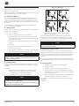
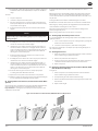
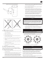
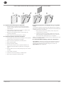
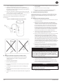
Draining Coolant
It is better to drain the coolant immediately after the compressor has been
operating as the coolant will drain faster and any contaminant will still be in
suspension.
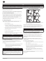
See Figure 1.
1. Place the straight end of the drain hose in a suitable container.
Install the other end of the drain hose in the drain valve. The
coolant ows through the drain hose automatically.
2. After drainage, remove the hose and close the valve.
NOTICE
On air cooled compressors, you may also drain coolant from the
coolant cooler by removing the plug.
You should also drain additional coolant from the airend by removing
the plug in the airend discharge elbow.
Figure 1: Coolant Drain
1 2
3 4
3. Dispose of waste coolant in accordance with local and
governmental regulations.
It is recommended to perform a coolant analysis every 2000 hours or
three months to monitor its condition and determine when to change the
coolant. If analysis is not performed, the recommended coolant change
interval is 8000 hours or two years, whichever comes rst.
NOTICE
Shorter coolant change intervals may be necessary if the compressor
is operated in adverse conditions.
Analyzing Food-Grade Coolant
It is highly recommended to have samples of the coolant analyzed every
500 hours or each month to determine when coolant should be changed.
If analysis is not performed, coolant should be changed after 2000 hours
or every six months when utilizing the food-grade lter supplied with the
compressor.
For compressors running food-grade coolant without the food-grade lter,
the change interval should be 1000 hours or six months, whichever comes
rst.
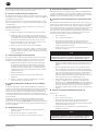
Sampling Coolant
1. Bring the compressor up to operating temperature.
2. Stop the compressor.
3. Isolate the compressor from the external air system.
4. Press the emergency stop to vent the separator tank and airend.
Fixed speed compressors can take more than two minutes to fully
de-pressurize once stopped.
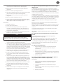
5. Draw a sample from the separator tank port using a pump kit. DO
NOT draw a sample from the drain port or oil lter.
Use a new hose on the pump for each sample. Failure to do this can give
false readings.
See Figure 2.
121714.07.03

EN-5 80446354 Rev D
EN
Figure 2: Coolant Sampling
Changing Coolant Filter
1. Remove drain plug from bottom of lter housing and drain coolant.
2. Loosen the lter housing.
3. Remove the element from the housing.
4. Place the old element in a sealed bag and dispose of in a safe way.
5. Remove the new replacement element from its protective package.
6. Apply a small amount of coolant to the element seal.
7. Install new replacement element into the lter housing.
8. Screw the housing to the lter head and tighten to the torque
specied on the housing.
9. Reinstall drain plug.
10. Start the compressor, check for leaks and check the coolant level.
Checking Separator Element
With the compressor running on load, check the separator dierential
pressure via the controller. It will be necessary to change the element if the
dierential pressure equals zero or exceeds 1 bar (15 psig).
Changing Separator Element
1. Remove the tting that holds the scavenge tube into the tank and
withdraw the tube assembly.
2. Disconnect the piping from the tank cover. Tag the lines if required.
Remove all the bolts securing the cover to the tank except the bolt
opposite the pivot bolt which should be left engaged by
2-3 threads with at least 6.5 mm (0.25 in) clearance from the screw
head to the cover. Rotate the jacking bolt clockwise until the cover
lifts o the tank at least 2 mm (0.08 in) all the way around the tank.
Remove the remaining bolt. The cover can now be rotated to allow
access to inside the tank.
3. Carefully lift the separator element up and out of the tank. Discard
the faulty element.
4. Clean the sealing surface on both the tank and its cover. Check the
tank to be absolutely certain that no foreign objects such as rags or
tools have been allowed to fall into the tank. Install a replacement
element down into the tank after checking the new element seal
for possible damage. Center the element within the tank ensuring
that it is fully seated in the sealing groove. Rotate the tank cover
back into position taking care not to damage the seal, and locate
the cover using two bolts but do not tighten down.
5. Loosen the jacking bolt to fully disengage the threads and tighten
the cover bolts in a cross-pattern to prevent over-tightening one
side of the cover. An improperly tightened cover will likely result in
a leak.
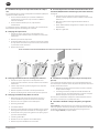
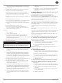
NOTICE
Unscrew the jacking bolt suciently to ensure that the cover can be
fully tightened down without imparting any stress onto the jacking
points. Tighten down the cover bolt to 81 N m (60 ft lb) for 75 kW
and smaller compressors or 200 N m (150 ft lb) for 90 kW and larger
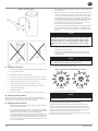
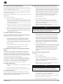
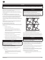
compressors. Refer to Figure 3 for the tightening sequence of the
bolts.
6. Inspect the tank scavenge screen and orice. Clean if necessary
following the instructions below.
7. Install the scavenge tube down into the tank until the tube just
touches the separator element and then raise it 3 mm (0.125 in).
Tighten ttings.
NOTICE
Take extreme caution to not force the scavenge tube into the tank.
This could potentially damage the separator element.
8. Install the piping in the original position.
Figure 3: Recommended Bolt Tightening Cross Pattern
3
5
1
9
7
4
6
2
10
8
3
11
5
1
9
7
4
12
6
2
10
8
55-75 kW90-160 kW
9. Start the compressor and check for leaks.
NOTICE
Do not use any form of sealant on either the separator tank or the
separator tank cover faces.
Inspecting Separator Tank / Pressure System
At 2000 hour intervals, inspect the external surfaces of the airend and
separator tank, including all ttings, for visible signs of impact damage,
excessive corrosion and abrasions. When changing the separator element,
inspect the internal components and surfaces. Any suspect parts shall be
replaced before the compressor is put back into service.
The separator tank should also be tested and inspected in accordance with
any national or local codes that may exist.
121714.07.03
EN
80446354 Rev D EN-6
Cleaning / Checking Scavenge Screen
The screen/orice assemblies are similar in appearance to a straight tubing
connector and will be located between two pieces of 6 mm (0.25 in)
O.D. scavenge line tubing.
The main body is made from 17 mm hexagon shaped metal and the diameter
of the orice and a direction-of-ow arrow is stamped in at areas of the
hexagon.
A removable screen and orice will require clearing as outlined in the
maintenance chart.
To remove the screen/orice:
1. Disconnect the scavenge line tubing from each end.
2. Hold the center section rmly and use a pair of pliers to gently
grasp the exit end of the assembly that seals against the scavenge
line tubing. The exit end is the end toward which the arrow is
pointing.
3. Pull the end out of the center section while using care to prevent
damage to the screen or sealing surfaces.
4. Clean and inspect all parts prior to reinstallation.
5. When the assembly is installed, conrm the direction of ow to
be correct. Observe the small arrow stamped in the center section
and ensure the direction ow to be from the separator tank to the
airend.
Replacing Coolant Hoses
The exible hoses that carry coolant through the cooling system may
become brittle with age and will require replacement. Replace them as
needed or every four years.
1. Depending on the location of the hose, it may contain compressor
coolant. It is recommended to drain the coolant into a clean
container. Cover the container to prevent contamination. If the
coolant is contaminated, replace with new coolant.
2. Remove the hose.
3. Install the new hose and rell the compressor with coolant.
4. Start the compressor, check for leaks and check coolant level. Rell
as necessary.
Checking Minimum Pressure Check Valve (MPCV)
The minimum pressure check valve (MPCV) shall be frequently tested and
regularly maintained. Remove it from the compressor for testing. If operating
conditions are particularly severe, the frequency of testing and maintenance
shall be increased accordingly. The user shall establish the frequency of
such tests as it is inuenced by such factors as the severity of the operating
environment.
The minimum pressure check valve (MPCV) should be tested and re-
calibrated in accordance with any national or local codes that may exist. If
no code exists, Ingersoll Rand recommends that the valve is recalibrated at
intervals of one year by a licensed contractor or qualied service personnel.
Changing Air Filter
1. Check the retaining cap for dirt and debris and wipe clean.
2. Unclip the retaining cap and withdraw the old element.
3. Fit the new element and ret the retaining cap.
Regreasing Motor
The blower motor contains pre-greased, sealed bearings. They cannot be
re-greased and do not require re-greasing. For the main motor, consult the
motor manufacturer to conrm that the motor may be greased and to obtain
instructions for regreasing.
Cleaning Air Cooled Sequential Cooling System
Air compressor operating temperatures will be higher than normal if the
external passages between the ns of the cooler cores become restricted
with foreign material. Regular cleaning of the cooler surfaces will support
the reliable operation of the air compressor system, improve the life of
the compressor coolant and improve overall compressor eciency. When
performed frequently as determined by site conditions and airborne
contamination, more signicant cleaning or replacement may not be
necessary.
1. Stop the compressor.
2. Isolate the compressor from the system.
3. Press the emergency stop to vent the separator tank and airend.
Fixed speed compressors can take more than two minutes to fully
de-pressurize once stopped.
4. Ensure that the main power disconnect switch is locked o and
tagged.
NOTICE
For any required lifting of air compressor parts or required tools,
always use the proper certied lifting equipment, and employ sound
working principles.
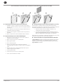
5. Visually check the outside of the cooler cores to determine the
appropriate cleaning method detailed as follows:
a. For loose dirt, dust and other light foreign material, open the
access panels on the sides of the cooler plenum and gently
blow compressed air across the coolant cooler surface. Use a
vacuum hose with a soft brush to clean the exposed face of the
air aftercooler. Repeat the process until the coolers are suciently
clean. Replace the access panels before returning the compressor to
service.
b. For thick, packed dirt, coolant or grease, or other heavy material,
the coolers will need to be removed from the compressor for
pressure washing. Ingersoll Rand does NOT support pressure
washing coolers when they are installed in the compressor due
to the dangers of spraying water in or around potential electrical
power sources. Follow the steps below for cooler removal.
Removing / Installing Air Cooled Cooler
To remove:
1. Stop the compressor.
2. Isolate the compressor from the system.
3. Press the emergency stop to vent the separator tank and airend.
Fixed speed compressors can take more than two minutes to fully
de-pressurize once stopped.
4. Ensure that the main power disconnect switch is locked o and
tagged.
NOTICE
For any required lifting of air compressor parts or required tools,
always use the proper certied lifting equipment, and employ sound
working principles.
5. Drain the coolant from the coolant cooler by removing the hex plug
located at the front of the air cooler, and lower side of the coolant
cooler.
6. Remove all hoses, pipes, and sensors from the coolers.
7. Remove the external sheet metal panels.
8. Remove the access panels on the sides of the cooler plenum.
9. Properly secure the air aftercooler and remove the four nuts from
the two bolts at the upper sides of the cooler.
10. Remove the two nuts from the bolts at the bottom of the cooler.
11. Carefully remove the air aftercooler.
12. Properly secure the coolant cooler and remove the four nuts from
the two bolts at the upper sides of the cooler.
13. Remove the two nuts from the bolts at the bottom of the cooler.
14. Carefully remove the coolant cooler.
121714.07.03

EN-7 80446354 Rev D
EN
15. Re-install the coolant drain plug to 23 N m (17 ft lb) for compressors
75 kW and smaller or 65 N m (48 ft lb) for compressors 90 kW and
larger.
To install:
1. Stop the compressor.
2. Isolate the compressor from the system.
3. Press the emergency stop to vent the separator tank and airend.
Fixed speed compressors can take more than two minutes to fully
de-pressurize once stopped.
4. Ensure that the main power disconnect switch is locked o and
tagged.
NOTICE
For any required lifting of air compressor parts or required tools,
always use the proper certied lifting equipment, and employ sound
working principles.
5. Carefully place the coolant cooler in its proper location and install
the two sets of lower nuts and bolts, tightly.
6. Install the two sets of upper side nuts and bolts, nger tight + ¼
turn. Next, add the second nut to each tightly. This second nut is
used to lock the rst in place. It is important the rst nut is not too
tight so it can allow the cooler to expand and contract without
stressing the cooler’s brazed joints.
7. Ensure the rubber seal on the air aftercooler is in place on the
cooler and in good condition.
8. Carefully place the air aftercooler cooler in its proper location and
install the two sets of lower nuts and bolts tightly.
9. Install the two sets of upper side nuts and bolts nger tight + ¼
turn. Next add the second nut to each tightly. This second nut is
used to lock the rst in place. It is important the rst nut is not too
tight so it can allow the cooler to expand and contract without
stressing the cooler’s brazed joints.
10. Re-attach all hoses, pipes and sensors, and properly torque
according to the Parts Information manual.
11. Replace the access panels on the sides of the cooler plenum.
12. Rell the compressor with coolant to the proper level, following the
process outlined in the “Adding Coolant” procedure.
Cleaning Water Cooled Cooler (for both Clean & Harsh Water
Options)
A periodic inspection and maintenance program should be implemented for
water cooled heat exchangers. It is recommended that you contact
Ingersoll Rand for cleaning services should you not have experience and
equipment to do this work.
If water inlet lines have strainers, inspect them and replace or clean as
required.
Mineral scale may be removed with a suitable de-scaling agent containing
amidosulphuric acid + citric acid and Neutralit solutions for cleaning the
coolers. As an alternative, any weak acid mixed with water in the ratio of 1:4
may be used.
Fouling should be removed with a suitable detergent in hot water.
Back ush the cooler with a ow rate at least 1.5 times the normal ow rate.
After using any cleaning solution, thoroughly ush out all chemicals with
clean water before returning the cooler to service.
Mechanical cleaning methods are not recommended as damage to the
internal passages may occur.
After cleaning, examine the cooler for erosion or corrosion.
Checking High Airend Temperature Sensor
It is recommended that the discharge temperature sensor (2ATT) is checked
regularly as follows:
a. For air cooled compressors, stop the cooling blower by opening the
blower / fan motor circuit breaker.
b. For water cooled compressors, shut o the cooling water.
The compressor should trip at 109 °C (228 °F). A trip warning will appear on
the controller display.
Cleaning Motor Cowl
1. Ensure the compressor is electrically isolated for at least 15 minutes
before commencing any maintenance work.
2. Remove the panels from the compressor.
3. Using a clean dry cloth, remove dust from the surface of the motor
cowl and ensure all ventilation slots are free of obstructions.
4. Replace the panels.
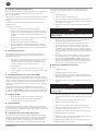
Removing / Replacing Starter Box Power Drive Module (PDM)
Filter Element (For VSD only)
See Figure 4.
1. Ensure compressor is electrically isolated for at least 15 minutes
before commencing any maintenance work.
2. Unclip the front grill of the starter box lter housing.
3. Remove the lter element from the housing and replace with a new
lter element.
4. Replace the front grill.
Figure 4: Starter Box Power Drive Module (PDM) Filter Element Replacement
121714.07.03

EN
80446354 Rev D EN-8
Cleaning / Checking Condensate Drain
1. Ensure the compressor is electrically isolated for at least 15 minutes,
before commencing any maintenance work.
2. Isolate the compressor from the system and fully discharge the
compressed air within the compressor.
3. Remove the tube from the tting located on the bottom of the
moisture separator.
4. Remove the bowl of the moisture trap, clean and replace.
Cleaning / Installing Package Pre-Filter
1. Unlatch the two 1/4 turn latches and open the intake panel (panel
is hinged)
2. Remove the six wing nuts and at washers.
3. Remove the lter grill.
4. Pull out the lter element.
5. Center the new element over the package intake opening. Also
note that the lter is washable with mild detergent.
6. Push the lter over the grill studs so that the studs poke through
the lter media.
7. Install the lter grill.
8. Install the six wing nuts and at washers.
9. Close the intake panel and latch.
Checking / Cleaning No Loss Drain Trap (where tted)
It is recommended to check the no loss drain trap daily to ensure that
condensate is draining from the moisture separator system. To check for
correct function:
1. Press the test button on the drain and listen for condensate / air
passing through the drain.
2. If the drain is clogged, replace the no loss drain valve service
module. The service module consists of the lower portion of the
drain trap and is not serviceable.
Additionally, it is recommended to replace the service module every
8000 hours or once per year, whichever comes rst.
Monitoring Fluid and Performing Shock Pulse Bearing
Analysis
Ingersoll Rand recommends incorporating predictive maintenance,
specically the use of coolant and shock pulse bearing analysis, into all
preventative maintenance programs. Contact Ingersoll Rand for details.
121714.07.03
EN-9 80446354 Rev D
EN
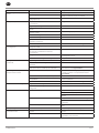
TROUBLESHOOTING
This section provides basic troubleshooting information. Determination of specic causes to problems are best identied by thorough inspections performed
by personnel instructed in safety, operation and maintenance of this equipment. The chart below provides a brief guide to common symptoms, probable
causes and remedies.
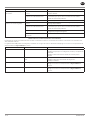
Table 3: General Faults
SYMPTOM CAUSE REMEDY
Compressor will not start. No power supply to compressor. Check supply is switched on. If so, contact a qualied
electrician.
Controller failure. Check supply to controller. Replace controller.
Starter failure. Isolate supply, lock o and tag. Replace failed component
or contact your local Ingersoll Rand representative.
Compressor stops and will not
restart.
Drive controller has tripped. See Tables 3 and 4.
Controller has tripped the compressor. See Tables 3 and 4.
Maximum number of starts per hour exceeded.
Compressor is stopped and will not
restart.
Controller has tripped the compressor and has not
been reset.
See Tables 3 and 4.
Emergency stop has been pressed and not released. Identify reason why, repair fault, disengage button and
reset controller.
Emergency stop has been pressed and released but
controller has not been reset.
Repair fault and reset controller.
Compressor will not meet pressure
required by system.
Compressor not sized to meet system requirements
or requirements have been changed.
Contact your local Ingersoll Rand representative.
Air loss due to pipe, hose, joint or seal failure. Repair or replace.
Air loss due to blowdown valve stuck open. Repair or replace.
Air loss through pressure relief valve not seating or
set incorrectly.
Repair or replace.
Air loss due to moisture separator drain trap stuck
open.
Repair or replace.
Motor speed too low caused by drive incorrectly set. Contact your local Ingersoll Rand representative.
Motor speed too low caused by fault in drive settings. See Table 4.
Controller fault. Repair or replace.
Drive motor fault. See Table 4.
Pressure transducer faulty, incorrectly calibrated or
EMF interference.
Recalibrate or replace.
Incorrect controller settings. Check and modify settings.
Inlet grill or ducting is blocked. Check and clean.
Air lter dirty or collapsed. Replace.
Compressor will not meet pressure
required by system.
Inlet valve not opening fully. Repair or replace.
Separator element dirty or collapsed. Replace.
Pipe / Hoses blocked or collapsed. Clean or replace.
Cooler core blocked. Clean or replace.
Minimum pressure check valve not functioning
correctly.
Repair or replace.
Equipment between compressor and customer
measuring point causing pressure drop / pressure
loss.
Review system requirements.
Pressure produced by compressor is
too high due to speed not reducing
as demand reduces.
Controller set incorrectly. Check and modify settings.
Pressure transducer may be faulty, incorrectly
calibrated or not receiving pressure signal.
Recalibrate or replace.
Drive settings fault. Contact your local Ingersoll Rand representative.
Compressor discharge air too hot. High ambient temperature. Review installation and system parameters.
Insucient cooling air. Check ducting and cooling air path, check direction of
blower rotation.
Dirty, blocked aftercooler (cooling air side). Clean or replace.
121714.07.03

EN
80446354 Rev D EN-10
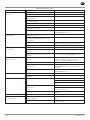
Table 3: General Faults (cont.)
SYMPTOM CAUSE REMEDY
Compressor package produces
excessive noise.
Panels or doors are not closed properly. Rectify fault.
Air leaks from internal pipework / components. Repair or replace.
Blower or blower motor bearings worn. Repair or replace.
Loose debris impacting on blower during rotation. Remove and rectify any damage.
Blowdown valve stuck open. Repair or replace.
Pressure relief valve not seating correctly. Repair or replace.
Vibration due to motor, airend or blower imbalance. Repair or replace.
Airend requires repair. Contact your local Ingersoll Rand representative.
Discharge air is contaminated with
coolant.
Scavenge pipe is blocked, broken or o-ring is not
sealing.
Clean or replace.
Separator element is punctured, or incorrect, or
requires changing, or not sealing correctly.
Replace.
Incorrect coolant has been added. Drain system, check for damage. Clean, rell with correct
coolant.
System has been overlled with coolant. Check for damage, drain excess.
Discharge air is contaminated with
condensate.
Aftercooler not functioning correctly. Clean or replace.
Moisture separator drain trap faulty. Repair or replace.
Continuous low speed / low ambient operation
causing condensate build up.
Review system requirements and contact your local
Ingersoll Rand representative.
Compressor package draws too much
current.
Compressor operating above rated pressure. Check and modify settings. Review system requirements
and contact your local Ingersoll Rand representative.
Separator lter element dirty or blocked. Replace.
Voltage supply is low or unbalanced. Contact your local Ingersoll Rand representative or a
qualied electrician.
Airend is damaged. Contact your local Ingersoll Rand representative.
Excessive coolant consumption. Coolant system leak. Repair or replace.
See also ‘discharge air is contaminated with coolant’. See above.
High dewpoint. Refrigeration compressor not supplied power. Check incoming power supply.
Check the dryer protection fuse.
Check auxiliary contact on main motor contactor.
Condensate system malfunction. Check operation of drain valve.
Check operation of condensate check valves.
Condenser dirty. Clean condenser and replace panel lter element.
Ice formation in dryer. Low evaporator pressure. Check hot gas valve setting.
Solenoid condensate valve will not
close
Debris in solenoid valve prevents diaphragm from
seating.
Remove solenoid valve, disassemble, clean and
reassemble.
Short in electrical component. Check and replace power cord or timer as needed.
121714.07.03

EN-11 80446354 Rev D
EN
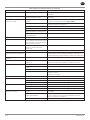
Table 4: Controller Faults (indicated on the controller)
FAULT CAUSE REMEDY
Emergency stop. Emergency stop button has been
pressed.
Identify reason why, repair fault, disengage button and reset controller.
Blower motor overload. Blower is blocked, damaged or blower
motor is faulty.
Remove blockage, repair or replace damaged components.
High airend discharge temperature. Compressor operating above rated
pressure.
Check and modify settings. Review system requirements and contact
your local Ingersoll Rand representative.
Low coolant level. Check for leaks. See also ‘discharge air is contaminated with coolant’.
Top up coolant.
High ambient temperature. Review installation and system parameters.
Insucient cooling air. Check ducting and cooling air path.
Dirty, blocked coolant cooler (cooling
air side).
Clean or replace.
Blower motor direction of rotation
incorrect.
Wire correctly.
Check setpoints. Controller software has been changed. Recalibrate all sensors and check setpoints.
Remote start failure. Remote start button is pressed after
compressor is running or remote start
button remains closed.
Check operation of buttons or operating procedures.
Remote stop failure. Remote stop button remains open and
either start button is pressed.
Check operation of buttons or operating procedures.
Sensor failure. Sensor is missing or faulty. Install, repair or replace faulty sensor.
Compressor trips indicating a high
compressor temperature.
Insucient cooling taking place. If compressor is watercooled or sea watercooled, check that the cooling
water is owing. Check that there is no air in the water cooling system.
Check that the strainer is not blocked.
Controller has tripped the
compressor.
A fault has occurred. Repair fault / reset controller.
Invalid calibration. Calibration done with pressure in
compressor.
Depressurize and re calibrate with pressure pipe to sensor
disconnected. If fault still exists, replace pressure transducer.
Low sump pressure. System leak. Located and repair.
Minimum pressure check valve faulty. Repair with service kit.
Blowdown valve faulty. Repair with service kit.
Loss of control power. Check 110V circuit breaker.
Check wiring.
Check contactor KM1.
Check motor rotation. Drive system fault. Contact your local Ingersoll Rand representative.
VSD communication failure. Communication wiring faulty. Check and replace if required.
Drive faulty. Contact your local Ingersoll Rand representative.
Controller faulty. Contact your local Ingersoll Rand representative.
VSD initialization fault. Communication wiring faulty. Check and replace if required.
Drive faulty. Contact your local Ingersoll Rand representative.
Controller faulty. Contact your local Ingersoll Rand representative.
Change separator element and/or
high sump pressure.
Faulty pressure transducer measurement. Calibrate and validate the wet sump and package discharge
transducers.
Moisture separator condensate drain
trap faulty.
Ensure condensate drain system is functioning properly, and
condensate is being drained. See Table 3: Troubleshooting Chart.
Separator element dirty or blocked. Change separator element.
Change HE lter (integrated dryer
models only).
Faulty pressure transducer measurement. Calibrate and validate the after cooler discharge and package
discharge transducers.
Moisture separator condensate drain
trap faulty.
Ensure condensate drain system is functioning properly, and
condensate is being drained. See Table 3: Troubleshooting Chart.
Blockage in dryer. Ensure dryer blockage is not due to freeze up from refrigerant leaks.
Dryer HE lter dirty or blocked. Change HE lter.
121714.07.03

EN
80446354 Rev D EN-12
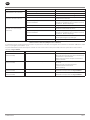
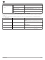
Table 5: Drive Faults (indicated on the controller)
The drive controller is directly linked to the controller. Faults in the drive controller will be displayed on the controller as ‘VSD fault 0, VSD fault 1’ etc.
The following VSD faults may be investigated and remedied at source. For all other VSD faults, contact your local Ingersoll Rand customer support
representative.
FAULT CAUSE ACTION
VSD Fault 1 Over-current. Check separator element.
Check cooler, pipework and moisture separator for blockages.
Check operation of minimum pressure check valve (MPCV).
VSD Fault 3 Drive temperature too high. Check drive lter, replace if necessary.
Check drive cooling fan circuit breaker.
Check wiring.
VSD Fault 22 Current overload. Check oil level and add oil as needed.
Contact your local Ingersoll Rand representative.
VSD Fault 23 Motor underspeed. Check oil level and add oil as needed.
Contact your local Ingersoll Rand representative.
121714.07.03

EN-13 80446354 Rev D
EN
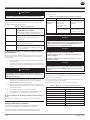
R37-75 INTEGRATED DRYER MAINTENANCE
WARNING
!
Before accessing live electrical parts, disconnect the power supply
to the dryer using the disconnect switch or disconnecting the cable
connections.
Maintenance Chart
For optimum performance from your dryer, follow the periodic maintenance
schedule described below.
Table 6: Maintenance Chart
WEEKLY CONDENSATE DRAINS (TIMED AND NO-LOSS
DRAINS)
Verify that the condensate drains are operating
correctly by pressing the TEST button.
EVERY 4 MONTHS CONDENSER
Remove any dust from the condenser ns.
EVERY 6 MONTHS AIR FILTER
Replace air lter element.
YEARLY (TIMED DRAINS ONLY)
Completely disassemble the drains and clean all
their components.
Cleaning Condensate Drains (Timed Drains Only)
Periodically clean the screen inside the valve to keep the drain functioning at
maximum capacity. To do this, perform the following steps:
1. Close the strainer ball valve completely to isolate it from the air
receiver tank.
2. Press the TEST button on the timer to vent the pressure remaining
in the valve. Repeat until all pressure is removed.
WARNING
!
High pressure air can cause injury from ying debris. Ensure the
strainer ball valve is completely closed and pressure is released from
the valve prior to cleaning.
3. Remove the plug from the strainer with a suitable wrench. If you
hear air escaping from the cleaning port, STOP IMMEDIATELY and
repeat steps 1 and 2.
4. Remove the stainless steel lter screen and clean it. Remove any
debris that may be in the strainer body before replacing the lter
screen.
5. Replace plug and tighten with wrench.
6. When putting the valve back into service, press the TEST button to
conrm proper function.
Testing Condensate Drains (No-Loss Drains Only)
Press the TEST button to conrm proper function.
Troubleshooting Condensate Drains (Electronic
Drains Only)
This section provides basic troubleshooting information. Determination
of specic causes to problems are best identied by thorough inspections
performed by personnel instructed in safety, operation and maintenance
of this equipment. The chart below provides a brief guide to common
symptoms, probable causes and remedies.
Table 7: Condensate Drain Troubleshooting Chart
TROUBLE CAUSE ACTION
Solenoid
condensate valve
will not close.
Debris in solenoid valve
prevents diaphragm
from seating.
Remove solenoid valve,
disassemble, clean and
reassemble.
Short in electrical
component.
Check and replace power
cord or timer as needed.
Disassembling the Integrated Dryer
NOTICE
The dryer shall be disassembled, charged or repaired by a refrigerant
specialist.
Refrigerant liquid and lubricating oil inside the refrigeration circuit
shall be recovered in compliance with current norms in the country
where the dryer is installed.
NOTICE
Refrigerant leaks may be identied by tripping of the refrigeration
overload protector.
If a leak is detected in the refrigerant circuit, seek technical assistance.
If a refrigerant leak occurs, thoroughly air the room before
commencing work.
NOTICE
In normal temperature and pressure conditions, the R-404A
refrigerant is a colorless, class A1/A1 gas with TVL value of 1000 ppm
(ASHRAE classication).
Decommissioning the Integrated Dryer
Decommission the dryer and the relevant packaging in compliance with the
rules locally in force.
Pay particular attention to the refrigerant, as it contains part of the
refrigerating compressor lubricating oil.
Contact a waste disposal and recycling utility.
Table 8: Integrated Dryer Materials of Construction
RECYCLING DISASSEMBLY
Frame and panels Steel / epoxy resin polyester
Heat exchanger (cooler) Stainless steel / aluminum
Pipes Copper
Insulation Gum synthetic
Compressor Steel / copper / aluminum / oil
Condenser Aluminum
Refrigerant R-404A
Valve Steel
121714.07.03

121714.07.03

121714.07.03

ingersollrandproducts.com
© 2014 Ingersoll-Rand
121714.07.03

80446354
Revisión D
Noviembre 2014
Conserve estas instrucciones
Compresor de aire de tornillo giratorio
Información de mantenimiento del
producto
R37-160
121714.07.03

ES
80446354 Rev D ES-2
ACERCA DE ESTE MANUAL . . . . . . . . . . . . . . . . . . . . . . . . . . . . . . . . . .2
PERSONAL . . . . . . . . . . . . . . . . . . . . . . . . . . . . . . . . . . . . . . . . . . . . . . . . .2
SEGURIDAD . . . . . . . . . . . . . . . . . . . . . . . . . . . . . . . . . . . . . . . . . . . . . . . .2
MANTENIMIENTO DEL COMPRESOR DE AIRE. . . . . . . . . . . . . . . . .3
Mensajes de Mantenimiento. . . . . . . . . . . . . . . . . . . . . . . . . . . . . . . .3
Tabla de Mantenimiento . . . . . . . . . . . . . . . . . . . . . . . . . . . . . . . . . .3
Mantenimiento Periódico . . . . . . . . . . . . . . . . . . . . . . . . . . . . . . . . . .4
Vericando el nivel de refrigerante . . . . . . . . . . . . . . . . . . . . . . . . . . . . . 4
Añadir refrigerante. . . . . . . . . . . . . . . . . . . . . . . . . . . . . . . . . . . . . . . . . . . . 4
Drenado de refrigerante . . . . . . . . . . . . . . . . . . . . . . . . . . . . . . . . . . . . . . . 4
Analizando el refrigerante de grado alimentario . . . . . . . . . . . . . . . . 4
Muestras de refrigerante. . . . . . . . . . . . . . . . . . . . . . . . . . . . . . . . . . . . . . . 4
Cambio del ltro del refrigerante. . . . . . . . . . . . . . . . . . . . . . . . . . . . . . . 5
Controlar el elemento del separador. . . . . . . . . . . . . . . . . . . . . . . . . . . . 5
Cambio del elemento separador. . . . . . . . . . . . . . . . . . . . . . . . . . . . . . . . 5
Inspección del tanque del separador / sistema de presión . . . . . . . . 5
Limpieza / control de la pantalla de purga. . . . . . . . . . . . . . . . . . . . . . . 6
Cambio de manguitos del refrigerante. . . . . . . . . . . . . . . . . . . . . . . . . . 6
Vericación de la válvula de control de la presión mínima (MPCV) 6
Cambio del ltro de aire . . . . . . . . . . . . . . . . . . . . . . . . . . . . . . . . . . . . . . . 6
Reengrasado del motor. . . . . . . . . . . . . . . . . . . . . . . . . . . . . . . . . . . . . . . . 6
Limpieza del sistema de refrigeración secuencial de aire . . . . . . . . . 6
Retirar/instalar el refrigerante de aire. . . . . . . . . . . . . . . . . . . . . . . . . . . 6
Limpieza del refrigerador de agua (para versiones de agua limpia y
dura) . . . . . . . . . . . . . . . . . . . . . . . . . . . . . . . . . . . . . . . . . . . . . . . . . . . . . . . . . 7
Control del sensor de temperatura del extremo del compresor alto 7
Limpieza del capó del motor . . . . . . . . . . . . . . . . . . . . . . . . . . . . . . . . . . . 7
Retirar / sustituir el módulo de conducción de la caja de arranque
(PDM) elemento de ltro (solo para VSD) . . . . . . . . . . . . . . . . . . . . . . . 7
Limpieza/control del drenaje de condensado. . . . . . . . . . . . . . . . . . . . 8
Limpieza/instalación del preltro del paquete .. . . . . . . . . . . . . . . . . . 8
Vericación/limpieza de la trampilla de drenaje sin pérdida (si hay)
. . . . . . . . . . . . . . . . . . . . . . . . . . . . . . . . . . . . . . . . . . . . . . . . . . . . . . . . . . . . . . 8
Control del análisis de uido y cojinetes de “Shock Pulse” . . . . . . . . 8
RESOLUCIÓN DE PROBLEMAS . . . . . . . . . . . . . . . . . . . . . . . . . . . . . . .9
R3775 MANTENIMIENTO DEL SECADOR INTEGRADO . . . . . . 14
Tabla de Mantenimiento . . . . . . . . . . . . . . . . . . . . . . . . . . . . . . . . 14
Limpieza de los drenajes de condensado (solo drenajes
planicados) . . . . . . . . . . . . . . . . . . . . . . . . . . . . . . . . . . . . . . . . . . . . . . . . . 14
Prueba de drenajes de condensado (sólo drenajes sin pérdida) . . 14
Resolución de problemas Drenajes de condensado (sólo drenajes
electrónicos). . . . . . . . . . . . . . . . . . . . . . . . . . . . . . . . . . . . . . . . . . 14
Desmonte el secador integrado . . . . . . . . . . . . . . . . . . . . . . . . . . . 14
Retirada del servicio del secador integrado . . . . . . . . . . . . . . . . . . 14
CONTENIDO
ACERCA DE ESTE MANUAL
PERSONAL
SEGURIDAD
El uso, inspecciones y mantenimiento adecuados aumentan la vida y la
utilidad del compresor. Es extremadamente importante que todos los
involucrados en el mantenimiento del compresor estén familiarizados con
los procedimientos de mantenimiento y reparaciones de estos compresores
y que sean físicamente capaces de realizar los procedimientos. Este personal
debe ser capaz de realizar lo siguiente:
1. Manejo seguro y adecuado de herramientas mecánicas comunes,
así como de herramientas especiales o recomendadas por
Ingersoll Rand.
2. Procedimientos de seguridad, precauciones y hábitos de trabajo
establecidos por normas industriales aceptadas.
Algunos procedimientos de mantenimiento son técnicos en su naturaleza
y exigen herramientas especiales, maquinaria, formación y experiencia
para ser realizados correctamente. En dichas situaciones, sólo permita
que técnicos formados de Ingersoll Rand realicen el mantenimiento del
compresor. El personal operativo no debe intentar llevar a cabo el servicio o
las inspecciones más allá de los procedimientos indicados en este manual.
Para más información, póngase en contacto con la planta de Ingersoll Rand
o el técnico más cercano.
Antes de realizar cualquier trabajo en el compresor, asegúrese de haber
aíslado, bloqueado y marcado la alimentación eléctrica y de que el compresor
haya sido liberado de toda presión. Asegúrese de que el compresor está
aislado eléctricamente durante al menos 15 minutos antes de comenzar todo
trabajo de mantenimiento. Consulte el manual de información de seguridad
del producto para más información.
Ingersoll Rand no puede saber ni facilitar todos los procedimientos con
los que realizar las reparaciones ni los riesgos/resultados de cada método.
Si se realizan procedimientos de mantenimiento no recomendados
concretamente por el fabricante, asegúrese de que las acciones realizadas no
pongan en peligro la seguridad.
Si no está seguro del procedimiento o pasos para el mantenimiento, coloque
el compresor en una situación segura antes de consultar con un técnico.
El uso de piezas de repuesto que no sean de Ingersoll Rand puede suponer
en riesgo para la seguridad, disminuir el rendimiento, aumentar la necesidad
de mantenimiento e invalidar todas las garantías.
Para más información, póngase en contacto con la planta de Ingersoll Rand
o el técnico más cercano.
El objetivo de este manual es facilitar directrices para el mantenimiento y la resolución de problemas del compresor.
Para ver documentación de apoyo, consulte la Tabla 1.
Tabla 1: Manuales de producto
Publicación Producto
Número de pieza o documento por región
América EMEA * Pacíco asiático
Manual de información de seguridad del
producto
Todos 80446313 80446156 80446321
Manuales de información del producto Todos 80446339 80446164 80446347
Manual de información de piezas de
producto
R37-45 kW 80448095
R55-75 kW 80446271
R132-160 kW Fase individual 80446057
R90-160 kW Bifásico 80446065
* Europa, Oriente Medio y África
También están disponibles las hojas de especicación del producto y los diseños de referencia.
121714.07.03

ES-3 80446354 Rev D
ES
MANTENIMIENTO DEL COMPRESOR DE AIRE
Mensajes de Mantenimiento
La advertencia de servicio y el LED parpadeante aparecerán en intervalos
determinados, dependiendo del nivel de servicio seleccionado. Consulte
el manual de información del producto para más información sobre la
conguración del nivel de servicio.
Tabla de Mantenimiento
El mantenimiento debe ser realizado según las recomendaciones a
continuación con la siguiente prioridad: (1) Realice el mantenimiento cuando
se lo indique el controlador;(2) Realice el mantenimiento en intervalos
marcados por un número determinado de horas o según el mantenimiento
programado o (3) Anualmente.
Tabla 2: Tabla de mantenimiento
Periodo Acción Artículo de mantenimiento
Cuando lo indique el
controlador
Sustituir Elemento de ltro de aire
Sustituir Elemento de ltro del refrigerante
Sustituir Elemento de ltro del refrigerante
Diaria Comprobar Conexiones y manguitos para pérdidas
Comprobar Nivel de refrigerante
Comprobar Funcionamiento de drenaje de condensado
Comprobar Controlador de indicadores de servicio
Comprobar Preltro del paquete para bloqueo
Mensual Inspeccionar Sistema de refrigeración secuencial con aire para bloqueo
Inspeccionar Pantallas de sistema de refrigeración secuencial con agua
Inspeccionar Elemento de ltro del módulo de conducción de la caja de arranque (PDM)
Análisis Agua del sistema de refrigeración secuencial con agua
Cada 500 horas Análisis Refrigerante de grado alimentario
Cada 1000 horas Sustituir Refrigerante de grado alimentario (si no utiliza el módulo del ltro de grado alimentario)
Sustituir Filtro del refrigerante de grado alimentario (si no utiliza el módulo del ltro de grado alimentario)
Cada 2000 horas o
3 meses
Inspeccionar Elemento de ltro de aire
Inspeccionar Elemento de ltro del refrigerante
Inspeccionar Elemento de ltro del módulo de conducción de la caja de arranque (PDM)
Sustituir Refrigerante de grado alimentario (si utiliza el módulo del ltro de grado alimentario)
Sustituir Módulo del ltro de grado alimentario
Análisis Cojinete de pulso de choque
Análisis Refrigerante
Cada 4000 horas o
6 meses
Inspeccionar Pantalla de purga para bloqueo
Sustituir Elemento de ltro de aire
Sustituir Elemento de ltro del refrigerante
Sustituir Elemento de ltro del módulo de conducción de la caja de arranque (PDM)
Sustituir Elemento de preltro de paquete
Limpiar Sistema de refrigeración secuencial de aire
Inspeccionar / Limpiar Sistema de refrigeración secuencial de agua
Grasa
Todos los motores (si es necesario)
Calibrar Transductores de presión
Análisis Refrigerante
Análisis Cojinete de pulso de choque
Cada 8000 horas o
anualmente
Sustituir Refrigerante estándar [cada 8000 horas o dos años]
Sustituir Elemento separador
Sustituir Módulo de servicio de drenaje de condensado sin pérdida
Reparación Kit de servicio de la válvula de control de presión mínima (MPCV)
Reparación Kit de servicio de válvula de admisión
16.000 Horas Sustituir Manguitos del refrigerante
Sustituir Puntas de contacto
AVISO
Revise y cambie los elementos de ltro de refrigerante y del separador más frecuentemente en entornos de funcionamiento sucios.
AVISO
Lea las placas de datos del motor o llame al fabricante del mismo para determinar las necesidades especícas de engrasado. Para motores que
requieran engrasado, engráselos más frecuentemente en ambientes duros o más elevados.
121714.07.03

ES
80446354 Rev D ES-4
Mantenimiento Periódico
Esta sección se reere a los distintos componentes que requieren
mantenimiento y sustitución periódicos.
Consulte la información de seguridad y los procedimientos de
mantenimiento antes de realizar cualquier mantenimiento en las siguientes
secciones.
Vericando el nivel de refrigerante
El nivel de refrigerante debe comprobarse todos los días. En el lado del
tanque del separador se encuentra un cristal de visualización del nivel
de refrigerante y, mientras la máquina funcione con carga, el refrigerante
siempre debe estar visible en el visualizador. La posición normal es a la mitad.
La máquina debe estar funcionando al menos 40 segundos para realizar esta
vericación.
Detenga la máquina, asegúrese de que la presión del colector sea 0 psig y
que se vea bien el refrigerante en el visualizador.
Añadir refrigerante
Al funcionar el compresor durante un mínimo de 40 segundos, el nivel del
refrigerante debe ser visible en el visor de cristal. Si no:
1. Detenga el compresor.
2. Aísle el compresor del sistema.
3. Pulse la parada de emergencia para ventilar el tanque del separador
y el extremo del compresor. Las unidades FS pueden tardar más de
dos minutos para despresurizarse por completo, una vez detenidas.
4. Desatornille lentamente la pieza de relleno del refrigerante para
vericar que toda la presión ha sido liberada.
5. Añada refrigerante.
6. Cambie la pieza de relleno del refrigerante y reinicie el compresor.
7. Vuelva a vericar el nivel de refrigerante.
8. Repita los pasos arriba indicados hasta que el nivel de refrigerante
sea visible en el cristal de visualización con el compresor tanto en
marcha como detenido.
AVISO
No añada refrigerante por la toma del compresor para evitar el relleno
excesivo, la saturación del elemento de ltro del separador y que el
refrigerante pase a otras partes.
Drenado de refrigerante
Es mejor drenar el refrigerante inmediatamente después de que el compresor
haya estado funcionando ya que el líquido drenará más rápidamente y, si
tiene algún contaminante, seguirá en suspensión.
Véase Figura 1.
1. Coloque el extremo derecho de la manguera de drenaje en un
contenedor adecuado. Instale el otro extremo de la manguera de
drenaje en la válvula de drenaje. El refrigerante uye a través de la
manguera de drenaje de forma automática.
2. Tras el drenaje, retire el manguito y cierre la válvula.
AVISO
En compresores refrigerados con aire, puede drenar el refrigerante
desde el refrigerador retirando el tapón.
También debe drenar el refrigerante adicional de la unidad de
compresión retirando el tapón en el codo de descarga de la unidad de
compresión.
Figura 1: Drenaje del refrigerante
1 2
3 4
3. Deshágase de los residuos de refrigerante de acuerdo con las
regulaciones locales y gubernamentales.
Se recomienda realizar un análisis de refrigerante cada 2000 horas o 3 meses
para supervisar la condición y determinar cuándo cambiar el refrigerante. Si
no se realiza un análisis, el intervalo de cambio de refrigerante recomendado
es cada 8000 horas o 2 años, lo que ocurra antes.
AVISO
Puede ser necesario cambiarlo con más frecuencia si el compresor
funciona en condiciones adversas.
Analizando el refrigerante de grado alimentario
Se recomienda analizar muestras del refrigerante cada 500 horas o todos los
meses si se utiliza el ltro de calidad alimenticia incluido con la máquina.
Si no se realiza el análisis, el refrigerante debe cambiarse cada 2000 horas
o cada seis meses si se utiliza el ltro de calidad alimenticia incluido con la
máquina.
Para unidades que funcionen con refrigerante de calidad alimenticia sin el
ltro de calidad alimenticia, el intervalo de cambio debe ser cada 1000 horas
o cada 6 meses, lo que ocurra antes.
Muestras de refrigerante
1. Suba la temperatura del compresor hasta llegar a la temperatura de
funcionamiento.
2. Para el compresor.
3. Aísle el compresor del sistema de aire externo.
4. Pulse el botón de emergencia para ventilar el depósito del
separador y la unidad de compresión. Una vez detenidos, los
compresores de velocidad ja tardarán más de dos minutos en
despresurizarse completamente.
5. Tome una muestra, utilizando el kit de bombeo, del puerto del
tanque del separador. No tome una muestra del puerto de drenaje
ni del ltro de aceite.
Utilice un nuevo manguito en la bomba para cada muestra. No hacerlo
puede falsear la lectura.
Ver Figura 2.
121714.07.03
A página está carregando...
A página está carregando...
A página está carregando...
A página está carregando...
A página está carregando...
A página está carregando...
A página está carregando...
A página está carregando...
A página está carregando...
A página está carregando...
A página está carregando...
A página está carregando...
A página está carregando...
A página está carregando...
A página está carregando...
A página está carregando...
A página está carregando...
A página está carregando...
A página está carregando...
A página está carregando...
A página está carregando...
A página está carregando...
A página está carregando...
A página está carregando...
A página está carregando...
A página está carregando...
A página está carregando...
A página está carregando...
A página está carregando...
A página está carregando...
A página está carregando...
A página está carregando...
A página está carregando...
A página está carregando...
A página está carregando...
A página está carregando...
A página está carregando...
A página está carregando...
A página está carregando...
A página está carregando...
A página está carregando...
A página está carregando...
A página está carregando...
A página está carregando...
-
 1
1
-
 2
2
-
 3
3
-
 4
4
-
 5
5
-
 6
6
-
 7
7
-
 8
8
-
 9
9
-
 10
10
-
 11
11
-
 12
12
-
 13
13
-
 14
14
-
 15
15
-
 16
16
-
 17
17
-
 18
18
-
 19
19
-
 20
20
-
 21
21
-
 22
22
-
 23
23
-
 24
24
-
 25
25
-
 26
26
-
 27
27
-
 28
28
-
 29
29
-
 30
30
-
 31
31
-
 32
32
-
 33
33
-
 34
34
-
 35
35
-
 36
36
-
 37
37
-
 38
38
-
 39
39
-
 40
40
-
 41
41
-
 42
42
-
 43
43
-
 44
44
-
 45
45
-
 46
46
-
 47
47
-
 48
48
-
 49
49
-
 50
50
-
 51
51
-
 52
52
-
 53
53
-
 54
54
-
 55
55
-
 56
56
-
 57
57
-
 58
58
-
 59
59
-
 60
60
-
 61
61
-
 62
62
-
 63
63
-
 64
64


Ingersoll-Rand R37-160 Product Maintenance Information
- Tipo
- Product Maintenance Information
em outras línguas
- español: Ingersoll-Rand R37-160
- français: Ingersoll-Rand R37-160
- English: Ingersoll-Rand R37-160
Artigos relacionados
-
Ingersoll-Rand R90-160 kW Informação do produto
-
-
-
-
-
-
-
-
-
Outros documentos
-
Makita MAC3000 Manual do usuário
-
Anova CA24 Manual do proprietário
-
Leupold 21 Pro Manual do usuário
-
GSW Chauffe-eau Polaris Manual do usuário
-
 dirna Bergstrom SlimFIT RENAULT NET Manual do usuário
-
 Seeley TBS Manual do proprietário
-
Honeywell CS10PE Portable Evaporative Air Cooler Manual do usuário
-
Elkay 1000002437 Instruções de operação
-
dirna Bergstrom SlimFit Manual do usuário
-

