80447113
Revision A
July 2013
Save These Instructions
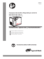
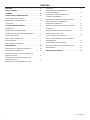
Contact-Cooled Rotary Screw Air Compressor
Installation, Operation and Maintenance
UP5 4, UP5 5, UP5 7, UP5 11c
UP6 5, UP6 7, UP6 10, UP6 15c
Installation, exploitation et maintenance
FR
Instalação, operação e manutenção
PT
Installation, Operation and Maintenance
EN
Instalación, operación y mantenimiento
ES
71113.13.16

2 80447113 Rev.A
CONTENTS
CONTENTS . . . . . . . . . . . . . . . . . . . . . . . . . . . . . . . . . . . . . . .2
FOREWORD . . . . . . . . . . . . . . . . . . . . . . . . . . . . . . . . . . . . . .3
SAFETY . . . . . . . . . . . . . . . . . . . . . . . . . . . . . . . . . . . . . . . . . . 4
INSTALLATION / HANDLING . . . . . . . . . . . . . . . . . . . . . .5
LOCATION IN THE PLANT . . . . . . . . . . . . . . . . . . . . . . . . . . . . . . . . . . . 5
DISCHARGE PIPING . . . . . . . . . . . . . . . . . . . . . . . . . . . . . . . . . . . . . . . . . 5
ELECTRICAL DATA . . . . . . . . . . . . . . . . . . . . . . . . . . . . . . . . . . . . . . . . . . 5
OPERATING INSTRUCTIONS . . . . . . . . . . . . . . . . . . . . . . 6
GENERAL OPERATION . . . . . . . . . . . . . . . . . . . . . . . . . . . . . . . . . . . . . . 6
COMPRESSOR CONTROLS . . . . . . . . . . . . . . . . . . . . . . . . . . . . . . . . . . 6
AUTOMATIC START & STOP CONTROL . . . . . . . . . . . . . . . . . . . . . . . 7
DUAL CONTROL . . . . . . . . . . . . . . . . . . . . . . . . . . . . . . . . . . . . . . . . . . . . 7
PRIOR TO STARTING . . . . . . . . . . . . . . . . . . . . . . . . . . . . . . . . . . . . . . . . 8
STARTING . . . . . . . . . . . . . . . . . . . . . . . . . . . . . . . . . . . . . . . . . . . . . . . . . . 8
NORMAL/EMERGENCY STOPPING . . . . . . . . . . . . . . . . . . . . . . . . . . 8
MAINTENANCE . . . . . . . . . . . . . . . . . . . . . . . . . . . . . . . . . .9
MAINTENANCE SCHEDULE . . . . . . . . . . . . . . . . . . . . . . . . . . . . . . . . . 9
ROUTINE MAINTENANCE . . . . . . . . . . . . . . . . . . . . . . . . . . . . . . . . . . . 9
TOP UP COOLANT PROCEDURE . . . . . . . . . . . . . . . . . . . . . . . . . . . . 10
COOLANT CHANGE PROCEDURE . . . . . . . . . . . . . . . . . . . . . . . . . . 10
COOLANT FILTER CHANGE PROCEDURE . . . . . . . . . . . . . . . . . . . 10
AIR FILTER ELEMENT CHANGE PROCEDURE . . . . . . . . . . . . . . . . 11
SEPARATOR ELEMENT CHANGE PROCEDURE . . . . . . . . . . . . . . . 11
COOLER CLEANING PROCEDURE . . . . . . . . . . . . . . . . . . . . . . . . . . 11
BELT CHECKING AND ADJUSTMENT PROCEDURE . . . . . . . . . . 11
ELECTRIC DRAIN VALVE . . . . . . . . . . . . . . . . . . . . . . . . . . . . . . . . . . . . 12
MOISTURE SEPARATOR MAINTENANCE . . . . . . . . . . . . . . . . . . . . 13
AIR FILTER MAINTENANCE . . . . . . . . . . . . . . . . . . . . . . . . . . . . . . . . . 13
DISASSEMBLING THE UNIT. . . . . . . . . . . . . . . . . . . . . . . . . . . . . . . . . 14
REFRIGERANT LEAKS IN THE REFRIGERATION CIRCUIT . . . . . 14
REFRIGERANT CHARGING . . . . . . . . . . . . . . . . . . . . . . . . . . . . . . . . . 14
CHARACTERISTICS OF REFRIGERANT R134A . . . . . . . . . . . . . . . 14
TROUBLESHOOTING . . . . . . . . . . . . . . . . . . . . . . . . . . . . . . . . . . . . . . . 14
MAINTENANCE . . . . . . . . . . . . . . . . . . . . . . . . . . . . . . . . . . . . . . . . . . . . 14
TROUBLE SHOOTING . . . . . . . . . . . . . . . . . . . . . . . . . . . . 15
71113.13.16

80447113 Rev.A 3
FOREWORD
The contents of this manual are considered to be proprietary
and condential to Ingersoll Rand and should not be
reproduced without the prior written permission of
Ingersoll Rand.
Nothing contained in this document is intended to extend
any promise, warranty or representation, expressed or
implied, regarding the Ingersoll Rand products described
herein. Any such warranties or other terms and conditions
of sale of products shall be in accordance with the standard
terms and conditions of sale for such products, which are
available upon request.
This manual contains instructions and technical data to
cover routine operation and scheduled maintenance tasks
by operation and maintenance sta. Major overhauls are
outside the scope of this manual and should be referred to an
authorised Ingersoll Rand service department.
Any modication to any part is absolutely prohibited and
would result in the CE certication and marking being
rendered invalid.
All components, accessories, pipes and connectors added to
the compressed air system should be:
of good quality, procured from a reputable manufacturer
and, wherever possible, be of a type approved by
Ingersoll Rand.
clearly rated for a pressure at least equal to the machine
maximum allowable working pressure.
compatible with the compressor lubricant/coolant.
accompanied with instructions for safe installation,
operation and maintenance.
Details of approved equipment are available from
Ingersoll Rand Service departments.
The use of non−genuine spare repair parts other than those
included within the Ingersoll Rand approved parts list may
create hazardous conditions over which
Ingersoll Rand has no control. Therefore Ingersoll Rand
does not accept any liability for losses caused by equipment
in which non−approved repair parts are installed. Standard
warranty conditions may be aected.
Ingersoll Rand reserves the right to make changes and
improvements to products without notice and without
incurring any obligation to make such changes or add such
improvements to products sold previously.
The intended uses of this machine are outlined below and
examples of unapproved usage are also given, however
Ingersoll Rand cannot anticipate every application or work
situation that may arise.
IF IN DOUBT CONSULT SUPERVISION.
This machine has been designed and supplied for use only in
the following specied conditions and applications:
Compression of normal ambient air containing no
known or detectable additional gases, vapors or
particles.
Operation within the ambient temperature range
specied in the PRODUCT SPECIFICATION SHEET.
•
•
•
•
•
•
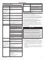
The use of the machine in any of the situation types listed
in table 1:−
Is not approved by Ingersoll Rand,
May impair the safety of users and other persons,
and
May prejudice any claims made against
Ingersoll Rand.
TABLE 1
Use of the machine to produce compressed air for:
direct human consumption
indirect human consumption, without suitable
ltration and purity checks
a)
b)
Use of the machine outside the ambient temperature
range specied in the PRODUCT SPECIFICATION SHEET.
Use of the machine where there is any actual or foreseeable
risk of hazardous levels of ammable gases or vapors.
THIS MACHINE IS NOT INTENDED AND MUST NOT BE USED
IN POTENTIALLY EXPLOSIVE ATMOSPHERES, INCLUDING
SITUATIONS WHERE FLAMMABLE GASES OR VAPOURS MAY
BE PRESENT.
Use of the machine tted with non Ingersoll Rand
approved components.
Use of the machine with safety or control components
missing or disabled.
The company accepts no responsibility for errors in
translation of this manual from the original English version.
a)
b)
c)
71113.13.16

4 80447113 Rev.A
SAFETY
Locate, read, understand and follow all Danger, Warning,
Caution, and Operating Instructions on the product and in all
Manuals. Failure to comply with safety precautions described
in the manuals supplied with the product, this manual or any
of the labels and tags attached to the product may result in
death, serious injury or property damage.
Check that all labels, tags and data (name) plates are in place
and legible.
It is your responsibility to make this information available to
others.
If you have any questions about safety or procedures not
included in this manual, ask your supervisor or contact any
Ingersoll Rand oce or qualied Ingersoll Rand distributor.
71113.13.16

80447113 Rev.A 5
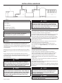
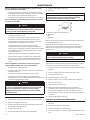
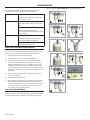
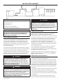
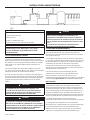
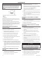
INSTALLATION / HANDLING
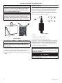
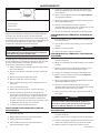
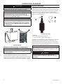
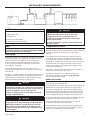
KEY
Compressor
Air Dryer
Air Receiver
Compressed air lters
System demand points
1)
2)
3)
4)
5)
NOTE
Items [2] to [5] are optional or may be existing items
of plant. Refer to your Ingersoll Rand distributor /
representative for specic recommendations.
LOCATION IN THE PLANT
NOTE
Ensure that the unit is wired for proper voltage before
installation.
The compressor can be installed on any level oor capable
of supporting it. A dry, well ventilated area where the
atmosphere is clean is recommended. A minimum of 1m (3ft)
should be left all around machine for adequate service access
and ventilation.
Adequate clearance needs to be allowed around and above
the machine to permit safe access for specied maintenance
tasks.
Ensure that the machine is positioned securely and on a
stable foundation. Any risk of movement should be removed
by suitable means, especially to avoid strain on any rigid
discharge piping.
CAUTION
Screw type compressors [1] should not be installed in
air systems with reciprocating compressors without
means of isolation such as a common receiver tank. It is
recommended that both types of compressor be piped
to a common receiver using individual air lines.
CAUTION
The use of plastic bowls on line lters and other plastic
air line components can be hazardous. Their safety can
be aected by either synthetic coolants or the additives
used in mineral oils. Ingersoll Rand recommends that
only lters with metal bowls should be used on any
pressurised system.
CAUTION
The standard compressor unit is not suitable for
operation in temperatures liable to cause freezing as
Condensate water is liable to be produced in the after
cooler and receiver where tted. Refer to your Ingersoll
Rand distributor for further information.
DISCHARGE PIPING
Discharge piping should be at least as large as the discharge
connection of the compressor. All piping and ttings should
be suitably rated for the discharge pressure.
It is essential when installing a new compressor [1], to review
the total air system. This is to ensure a safe and eective
total system. One item which should be considered is liquid
carryover. Installation of air dryers [3] is always good practice
since properly selected and installed they can reduce any
liquid carryover to zero.
It is good practice to locate an isolation valve close to the
compressor and to install line lters [4].
It is a requirement for air dryers covered under Aircare
that correctly sized Ingersoll Rand pre and afterlters are
installed.
ELECTRICAL DATA
An independent electrical isolator or disconnect should be
installed adjacent to the compressor.
Feeder cables/wires should be sized by the customer/
electrical contractor to ensure that the circuit is balanced
and not overloaded by other electrical equipment. The
length of wiring from a suitable electrical feed point is
critical as voltage drops may impair the performance of the
compressor.
Feeder cables / wires connections to isolator or disconnect
should be tight and clean.
The applied voltage must be compatible with the motor and
compressor data plate ratings.
The control circuit transformer has dierent voltage tappings.
Ensure that these are set for the specic applied voltage prior
to starting.
CAUTION
Never test the insulation resistance of any part of
the machines electrical circuits, including the motor
without completely disconnecting the electronic
controller (where tted).
CAUTION
Ensure that the motor rotates in the correct direction as
indicated by direction arrows.
71113.13.16

6 80447113 Rev.A
OPERATING INSTRUCTIONS
GENERAL OPERATION
The compressor is an electric motor driven, single stage
screw compressor, complete with accessories piped, wired
and baseplate mounted. It is a totally self contained air
compressor package.
The standard compressor is designed to operate in an
ambient range of 35.6°F - 104°F (2°C to 40°C). The maximum
temperature is applicable up to a maximum elevation
of 3280ft (1000m) above sea level. Above this altitude
signicant reduction in maximum allowable ambient
temperature is required.
Compression in the screw type air compressor is created by
the meshing of two (male & female) helical rotors.
The air/coolant mixture discharges from the compressor
into the separation system. This system removes all but a
few PPM of the coolant from the discharge air. The coolant
is returned to the cooling system and the air passes through
the aftercooler and out of the compressor.
Cooling air is moved through the coolers by the cooling fan
and discharged from the machine.
CAUTION
Cooling air is drawn in at the end of the machine
package passing through the lter and cooler before
being discharged from the top of the machine. Care
should be taken to avoid blocking the airow, or
causing any restriction in excess of the maximum
backpressure allowed for ducting.
Do not direct the airow at face or eyes.
By cooling the discharge air, much of the water vapour
naturally contained in the air is condensed and may be
drained from the downstream piping and equipment.
The coolant system consists of a sump, cooler, thermostatic
valve and a lter. When the unit is operating, the coolant is
pressurized and forced to the compressor bearings.
The compressor load control system is automatic on-o line.
This allows the compressor to maintain a set discharge line
pressure by varying output capacity to match the system
demand. The unit is provided with an automatic stop and
restart system for use in plants where the air demand varies
suciently to allow a compressor to shut down and save
power. Signicant system volume will assist this and is
recommended.
When the compressor is equipped with the optional dryer,
the dryer will cycle on and o with the compressor.
WARNING
When the unit stops running as the result of low air
demand, normally indicated by auto restart light, it
may restart and return to load at any time.
Safety of operation is provided as the compressor will
shut down if excessive temperatures or electrical overload
conditions should occur.
CAUTION
This unit is not designed or intended to operate when
contaminated with silicone. Lubricants, greases or
other items containing silicone should not be used on
this unit.
CAUTION
LOW DEMAND APPLICATIONS
During periods of low demand, the compressor may
not reach its normal operating temperature. Sustained
operation at low demand can result in the build up
of condensate in the coolant. If this situation occurs,
the lubricating characteristics of the coolant can be
impaired which may lead to damage of the compressor.
THE COMPRESSOR SHOULD BE ALLOWED AMPLE
LOADED RUNNING TIME OF AT LEAST 10 MINUTES PER
HOUR DURING NORMAL DAILY USE.
COMPRESSOR CONTROLS
DIRECT ONLINE STARTING:
The compressor is equipped for Automatic Start & Stop
Control.When the receiver tank pressure reaches the factory
pre–set maximum pressure, the pressure switch stops the
unit. When the receiver tank pressure drops below the factory
pre–set minimum. The pressure switch resets and restarts the
unit.
The pressure switch cover can be removed by unscrewing the
two screws holding the cover.
PRESSURE SWITCH ADJUSTMENT:
The compressor package will cut–in and cut–out at factory
preset pressure settings. Adjust the pressure switch only if
absolutely necessary. Adjustments are to be carried out only
when the switch is mounted, under pressure and voltage–
free.
WARNING
High voltage is present at the pressure switch contacts
when the power supply is connected. Disconnect,
lock and tag main power supply before making
adjustments.
WARNING
Do not adjust the pressure switch to exceed the
maximum discharge pressure of the unit.
NOTE
When replacing the pressure switch cover, ensure the
selector knob on the cover and the lever on the switch
are both in the ”OFF” position.
NOTE
When the compressor is equipped with the optional
dryer and lters, the pressure switch dierential should
be increased 10psi to account for the added pressure
drop of the lters and dryer.
71113.13.16

80447113 Rev.A 7
OPERATING INSTRUCTIONS
1
2
22505309 REV. A
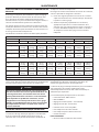
AUTOMATIC START & STOP CONTROL
NOTE
Automatic Start & Stop Control is intended for use
when the motor will start no more than 6 times per
hour.
When the receiver tank pressure reaches the factory pre–set
maximum pressure, the pressure switch stops the unit. When
the receiver tank pressure drops below the factory pre–set
minimum, the pressure switch resets and restarts the unit.
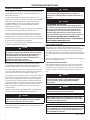
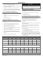
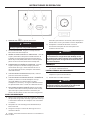
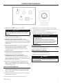
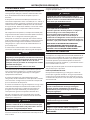
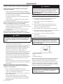
DUAL CONTROL
Select either automatic start and stop control or constant
speed control by adjusting the knob on the auxiliary valve.
For automatic start and stop control, turn the knob on the
auxiliary valve fully clockwise to disable the auxiliary valve.
The pressure switch will then start and stop the unit.
Auxiliary Valve.
A. Knob
B. Clockwise
C. Counterclockwise
Select constant speed control if the unit restarts in less
than 10 minute intervals or runs more than 40 minutes per
hour. Turn the knob fully counterclockwise to run the unit
continually.
NOTE
The auxilIary valve is factory pre–set at 5 psig (0,3 bar)
lower than the factory pressure switch setting.
CAUTION
Running unloaded with no air demand, will cause the
unit to be shuto by the pressure switch.
71113.13.16

8 80447113 Rev.A
OPERATING INSTRUCTIONS
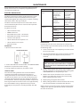
PRESSURE GAUGE -Indicates the system pressure.
WARNING
DO NOT operate the compressor at discharge
pressures exceeding the maximum operating
pressure.
HOURMETER - Records the total running time of the
compressor.
STOP BUTTON / EMERGENCY STOP - When depressed
will stop the compressor immediately. The ’Power on’
indicator will remain illuminated. The STOP button must
be released before the compressor can be restarted.
ON PUSH BUTTON SWITCH -When depressed will cause
the unit to start and run in a loaded condition if there is
a demand for air. If there is no demand, the machine will
stop automatically.
POWER ON INDICATOR LIGHT (Green) - Indicates the
presence of control voltage.
STOPPED/AUTO RESTART INDICATOR LIGHT (Amber)
- Will illuminate when the machine has shut-down due
to low air demand. The machine will restart and load
automatically as soon as the demand for air returns.
DEW POINT INDICATOR (Dryer Option) - Green indicates
good dew point. Red indicates ew point above 50°F
(10°C) Blue indicates freezing.
PRIOR TO STARTING
Make visual check of the machine, ensure that all guards
secure and that nothing is obstructing the proper
ventilation of, or free access to the machine.
Check coolant level. Add if necessary.
Make sure air discharge valve is open.
Turn on electrical isolator or disconnect. The Power on
(5) indicator will light, indicating that line and control
voltages are available.
Check direction of rotation at initial start or following
interruption in power supply.
1)
2)
3)
4)
5)
6)
7)
1)
2)
3)
4)
5)
WARNING
Make sure that all protective covers are in place.
Cooling air ow exhaust may contain ying
debris. Safety protection should be worn at all
times to avoid injury.
STARTING
Press the START button. The compressor will start and
then load automatically.
NORMAL/EMERGENCY STOPPING
Press STOP button (3) and the compressor will stop
immediately.
Turn o electrical isolator or disconnect.
CAUTION
After shutdown never allow unit to stand idle with
pressure in receiver/separator system.
1)
1)
2)
71113.13.16

80447113 Rev.A 9
MAINTENANCE
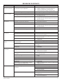
MAINTENANCE SCHEDULE
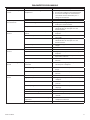
UP SERIES MAINTENANCE SCHEDULE
PERIOD MAINTENANCE
Each 24 hours opera-
tion
Check the coolant level and replenish if
necessary.
Visual check of
machine for any
leaks, dust build up
or unusual noise or
vibration
Report immediately, contact Ingersoll
Rand authorized distributor for assist-
ance if in doubt.
When compressor is
receiver mounted
Drain air receiver of condensate, or check
that automatic drain is operating.
Visual check condi-
tion of package
pre-lter
Blow clean if needed.
First 150 hours Change the coolant lter.
Each month or 100
hours
Remove and clean package pre-lter,
replace if needed Check the cooler(s)
for build up of foreign matter.Clean if
necessary by blowing out with air or by
pressure washing.
Every 1000 hours Analyze food grade lubricant (Ultra FG)
Each year or 2000
hours
Check the operation of the high tempera-
ture protection switch (109˚C).
Replace elements in IRGP and IRHE lters.
Change the coolant lter.
Check scavenge screen for blockage,
clean if required.
Change the separator element.
Change the Air Filter element.
Take coolant sample for uid analysis
(Ultra/Ultra EL).
Change the package pre–lter.
Check Drive Belts.
Motors with grease ttings-grease per
motor data TAG
Every 6000 Hours Replace food grade lubricant(Ultra FG).
Check and replace all items included
within 2000 hour service.
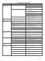
1 year external and
6 years internal pres-
sure vessel inspec-
tion. Frequency may
be otherwise dened
by local or national
legislation.
Separator vessel and air receiver when
tted
Fully inspect all external surfaces, and
ttings. Report any excessive
corrosion, mechanical or impact damage,
leakage or other
deterioration.
Every two years or
8000 hours
Change drive belts.
Replace Premium Coolant (Ultra) at
whichever interval occurs rst.
Check and replace all items included
within 2000 hour service.
Fit the following reconditioning parts as
appropriate:
Solenoid valves
Inlet valve kit
Minimum Pressure valve kit
Thermostatic Valve Kit
16000 hours or every
3 years
Replace Extended-life Premium Coolant
(Ultra EL)
Every 4 years or 16000
hours
Replace all hoses.
Strip, clean and re–grease motor bearings
on motors with grease ttings
Fit replacement electrical contactor tips.
Motors without grease ttings - replace
sealed bearings
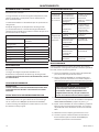
ROUTINE MAINTENANCE
This section refers to the various components which require
periodic maintenance and replacement.
It should be noted that the intervals between service
requirement may be signicantly reduced as a consequence
of poor operating environment. This would include eects of
atmospheric contamination and extremes of temperature.
The SERVICE/MAINTENANCE CHART indicates the
various components’ descriptions and the intervals when
maintenance has to take place. Oil capacities, etc., can be
found in the PRODUCT INFORMATION SHEET.
Compressed air can be dangerous if incorrectly handled.
Before doing any work on the unit, ensure that all pressure
is vented from the system and that the machine cannot be
started accidentally.
CAUTION
Before beginning any work on the compressor, open,
lock and tag the main electrical disconnect and close
the isolation valve on the compressor discharge.
Vent pressure from the unit by slowly unscrewing the
coolant ll cap one turn. Unscrewing the ll cap opens
a vent hole, drilled in the cap, allowing pressure to
release to atmosphere. Do not remove the ll cap until
all pressure has vented from the unit. Also vent piping
by slightly opening the drain valve. When opening the
drain valve or the coolant ll cap, stand clear of the
valve discharge and wear appropriate eye protection.
Ensure that maintenance personnel are properly trained,
competent and have read the Maintenance Manuals.
Prior to attempting any maintenance work, ensure that:-
all air pressure is fully discharged and isolated from the
system. If the automatic blowdown valve is used for this
purpose, then allow enough time for it to complete the
operation.
the machine cannot be started accidentally or otherwise.
all residual electrical power sources (mains and battery)
are isolated.
•
•
•
71113.13.16

10 80447113 Rev.A
MAINTENANCE
Prior to opening or removing panels or covers to work
inside a machine, ensure that:-
anyone entering the machine is aware of the reduced
level of protection and the additional hazards, including
hot surfaces and intermittently moving parts.
the machine cannot be started accidentally or otherwise.
Prior to attempting any maintenance work on a running
machine, ensure that:-
DANGER
Only properly trained and competent persons should
undertake any maintenance tasks with the compressor
running or with electrical power connected.
the work carried out is limited to only those tasks which
require the machine to run.
the work carried out with safety protection devices
disabled or removed is limited to only those tasks
which require the machine to be running with safety
protection devices disabled or removed.
all hazards present are known (e.g. pressurised
components, electrically live components, removed
panels, covers and guards, extreme temperatures, inow
and outow of air, intermittentlymoving parts, safety
valve discharge etc.).
appropriate personal protective equipment is worn.
loose clothing, jewellery, long hair etc. is made safe.
warning signs indicating that Maintenance Work is in
Progress are posted in a position that can be clearly
seen.
Upon completion of maintenance tasks and prior to
returning the machine into service, ensure that:-
the machine is suitably tested.
all guards and safety protection devices are retted and
correctly working.
all panels are replaced, canopy and doors closed.
hazardous materials are eectively contained and
disposed of in a manner compliant with local or National
environmental protection codes.
WARNING
Do not under any circumstances open any drain valve
or remove components from the compressor without
rst ensuring that the compressor is FULLY SHUT-
DOWN, power isolated and all air pressure relieved
from the system.
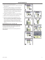
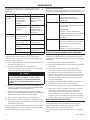
TOP UP COOLANT PROCEDURE
Slowly remove ll cap.
Pour coolant into spout untill spout almost overows.
Replace and tighten oil ll cap.
Start unit for about 10 seconds (until coolant drains out
the bottom of the sight glass).
Slowly remove ll cap.
Re–ll into spout until spout almost overows.
•
•
•
•
•
•
•
•
•
•
•
•
1)
2)
3)
4)
5)
6)
Replace and tighten oil ll cap.
Run unit.
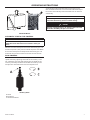
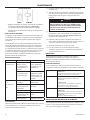
NOTE
Coolant level is correct when a unit is showing coolant
in bottom half of sight glass when up to operating
temperature (ten minutes running loaded).
A. Correct at operating temperature
B. Too much
C. OK
D. Too little
Repeat this procedure to get coolant to proper level when up
to operating temperature.
When the unit is shut down, coolant will usually ll up
sight glass. Do not adjust level based on level at shutdown.
Proper level is always set for a running unit at operating
temperature.
CAUTION
Ensure that Ingersoll premium coolant is used. Failure
to do so will void manufacturer warrenty.
COOLANT CHANGE PROCEDURE
It is better to drain the coolant immediately after the
compressor has been operating as the liquid will drain more
easily and any contaminant will still be in suspension.
Stop the machine, electrically isolate and vent all trapped
pressure.
Place a suitable container close to the drain valve.
Slowly remove ll cap.
Remove plug from drain valve.
Open the drain valve and drain coolant into container.
Close the drain valve.
Replace plug in drain valve.
Rell the machine following the ”top up coolant”
procedure above. After initial ll, to purge any airlocks,
the machine should be run for a few minutes cycling
between load and no load, before checking that the level
is correct.
Replace and tighten oil ll cap.
COOLANT FILTER CHANGE PROCEDURE
Stop the machine, electrically isolate and vent all trapped
pressure.
Loosen lter with the correct tool.
Remove the lter from the housing.
Place the old lter in a sealed bag and dispose of in a safe
way.
7)
8)
1)
2)
3)
4)
5)
6)
7)
8)
9)
1)
2)
3)
4)
71113.13.16

80447113 Rev.A 11
MAINTENANCE
Clean the mating face of the housing taking care to avoid
any particles entering the machine.
Remove the new Ingersoll Rand replacement lter from
its protective package.
Apply a small amount of lubricant to the lter seal.
Screw the new lter down until the seal makes contact
with the housing, then hand tighten a further half turn.
Start the compressor and check for leaks.
AIR FILTER ELEMENT CHANGE PROCEDURE
Stop the machine, electrically isolate and vent all trapped
pressure.
Unscrew the retaining cap and withdraw the old
element.
Fit the new element.
Replace the retaining cap.
SEPARATOR ELEMENT CHANGE PROCEDURE
Stop the machine, electrically isolate and vent all trapped
pressure.
Loosen separator element with the correct tool.
Remove the element from the housing; place it in a
sealed bag and dispose of it safely.
Clean the mating face of the housing.
Remove the new Ingersoll Rand replacement element
from its protective package.
Apply a small amount of lubricant to the element seal.
Screw the new element down until the seal makes
contact with the housing, then hand tighten a further
half turn.
Start the compressor and check for leaks.
5)
6)
7)
8)
9)
1)
2)
3)
4)
1)
2)
3)
4)
5)
6)
7)
8)
CAUTION
This unit is not designed or intended to operate when
contaminated with silicone. lubricants, greases or other
items containing silicone should not be used on this
unit.
COOLER CLEANING PROCEDURE
Stop the machine, electrically isolate and vent all trapped
pressure.
Remove the top cover to obtain access to the cooler.
Clean the cooler.
Rebuild in reverse order.
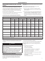
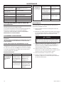
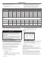
BELT CHECKING AND ADJUSTMENT PROCEDURE
Check belt tension occasionally, especially if looseness is
suspected. A quick check to determine if adjustment is
proper may be made by observing the slack side of the belt
for a slight bow when the unit is in operation.
If a slight bow is evident, the belt is usually adjusted
satisfactorily.
A belt tension measurement device can be used to determine
the tension of the belt.
Belt tensioning can be achieved by loosening the airend
anchor screws, a belt tensioning bolt is provided to aid in
moving the airend.
Follow the procedures outlined below to correctly set and
measure belt tension.
Lay a straight edge across the top outer surface of the
belt drive frompulley to sheave.
At the center of the span, perpendicular to the belt, apply
pressure to the outer surface of the belt with a tension gauge.
Force the belt to the deection indicated in the table below,
and compare the reading on the tension gauge to the gures
shown.-Belt tension
1)
2)
3)
4)
1)
BELT TENSION
5hp/4kw * 7.5hp/5.5kw * 10hp/7.5kw * 15hp/11kw **
New Used New Used New Used New Used
60hz
125 psig 75 Lb
(34 Kg)
62 Lb
(28 Kg)
110 Lb
(50 Kg)
90 Lb
(41Kg)
110 Lb
(50 Kg)
90 Lb
(41Kg)
140 Lb
(64 Kg)
120 Lb
(54 Kg)
150 psig 75 Lb
(34 Kg)
62 Lb
(28 Kg)
90 Lb
(41Kg)
75 Lb
(34 Kg)
110 Lb
(50 Kg)
90 Lb
(41Kg)
140 Lb
(64 Kg)
120 Lb
(54 Kg)
210 psig 75 Lb
(34 Kg)
62 Lb
(28 Kg)
90 Lb
(41Kg)
75 Lb
(34 Kg)
110 Lb
(50 Kg)
90 Lb
(41Kg)
150 Lb
(68 Kg)
125 Lb
(57 Kg)
50hz
8 bar 85 Lb 70 Lb 85 Lb 70 Lb 110 Lb 90 Lb 140 Lb 120 Lb
(39 Kg) (32 Kg) (39 Kg) (32 Kg) (50 Kg) (41Kg) (64 Kg) (54 Kg)
10 bar 90 Lb 75 Lb 85 Lb 70 Lb 120 Lb 100 Lb 140 Lb 120 Lb
(41Kg) (34 Kg) (39 Kg) (32 Kg) (54 Kg) (45 Kg) (64 Kg) (54 Kg)
14.5 bar 90 Lb 75 Lb 100 Lb 80 Lb 120 Lb 100 Lb 150 Lb 125 Lb
(41Kg) (34 Kg) (45 Kg) (36 Kg) (54 Kg) (45 Kg) (68 Kg) (57 Kg)
* ”Krikit I”gauge or equal
** ”Krikit II”gauge or equal
71113.13.16

12 80447113 Rev.A
MAINTENANCE
Ensure the pulley and sheave are properly aligned and the
motor anchor screws are adequately retightened prior to
restarting the compressor.
ELECTRIC DRAIN VALVE
PRODUCT DESCRIPTION
The Electric Drain Valve removes condensed water and oil
from the moisture sepearator. Additional drains may be
installed throughout your compressed air system, including
aftercoolers, lters, drip legs and dryers.
The Electric Drain Valve operates on a timer which can be
set to automatically drain the air receiver tank at operator–
determined intervals.
Key features include:
100% continuous duty
NEMA 4 enclosure
Adjustable time on (0.5 – 10 seconds)
Adjustable time o (0.5 – 45 minutes)
Stainless steel operator
LED to indicate electrical power is on
LED to indicate valve is open
Manual override
OPERATION
1. Open the strainer ball valve.
Strainer ball valve
OPEN CLOSED
2. Set the “time o” and “time on” knobs. See TIMER SETTINGS
(below) for an explanation of the settings.
3. During compressor operation, check for air leaks.
TIMER SETTINGS
The “time o” setting determines the interval between
cycles from 30 seconds to 45 minutes. The “time on”
setting determines the actual time the compressor drains
condensate. The timer’s cycle rate and drain opening time
should be adjusted to open just long enough to discharge
the condensate. The timer is properly set when it opens and
discharges condensate and then vents air for approximately
one second before closing. Adjustments may be made
depending on many factors, including humidity and duty
cycle.
•
•
•
•
•
•
•
•
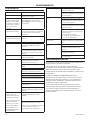
TROUBLESHOOTING
TROUBLE CAUSE ACTION
Valve will not
close.
1. Debris in
solenoid valve
prevents dia-
phragm from
seating.
1. Remove
solenoid valve,
disassemble,
clean and
reassemble.
2. Short in
electrical
component.
2. Check and
replace power
cord or timer as
needed.
Timer will not
activate
1. No electrical
supply.
1. Apply power.
2. Timer
malfunction.
2. Replace timer.
3. Clogged port. 3. Clean valve.
4 Solenoid valve
malfunction.
4. Replace
solenoid valve.
5. Clogged
strainer.
5. Clean strainer.
MAINTENANCE
Periodically clean the screen inside the valve to keep the
drain functioning at maximum capacity. To do this, perform
the following steps:
lose the strainer ball valve completely to isolate it from
the air receiver tank.
Press the TEST button on the timer to vent the pressure
remaining in the valve. Repeat until all pressure is
removed.
CAUTION
High pressure air can cause injury from ying
debris. Ensure the strainer ball valve is completely
closed and pressure is released from the valve prior
to cleaning.
Remove the plug from the strainer with a suitable
wrench. If you hear air escaping from the cleaning port,
STOP IMMEDIATELY and repeat steps I and 2.
Remove the stainless steel lter screen and clean it.
Remove any debris that may be in the strainer body
before replacing the lter screen.
Replace plug and tighten with wrench.
When putting the Electric Drain Valve back into service,
press the TEST button to conrm proper function.
Before accessing live electrical parts, disconnect the power
supply to the dryer using disconnect switch or disconnect
the cable connections.
1)
2)
4)
5)
6)
7)
71113.13.16

80447113 Rev.A 13
MAINTENANCE
PREVENTIVE MAINTENANCE
For optimum performance from your dryer, follow the
periodic maintenance schedule described below.
WEEKLY
CONDENSATE DRAINS
Verify that the condensate drains are
operating correctly.
EVERY 4 MONTHS
CONDENSER
Remove any dust from the con-denser
ns.
COMPRESSOR
Make sure compressor power
consumption complies with data plate
specications.
YEARLY
CONDENSATE DRAINS
Completely disassemble the drains
and clean all their components.
AIR FILTER
Replace air lter element.
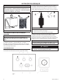
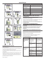
MOISTURE SEPARATOR MAINTENANCE
The moisture separator will operate indenitely under
normal working conditions, however at some time it may be
necessary to replace the seals should the housing leak.
Isolate the housing from the air supply.
Fully depressurize in drain bowl as appropriate.
Unscrew bowl and remove. If pressure has not been
completely released from the housing, air will escape
from the warning hole giving an audible alarm. Screw
back bowl and repeat instruction 2 before attempting
again. Should resistance to unscrewing be experienced,
provision is made for a ’C’ spanner to t onto the ribs of
the bowl.
Check condition of bowl seal and replace if necessary.
Clean screw threads.
Ret bowl with ’O’ ring seal.
Repressurize and check for leaks. If leaks occur they will
most probably be from the bowl ’O’ ring. Depressurize
housing and remove ’O’ ring as stated above and inspect
and clean. Ensure that mating surfaces are clean and
then ret ’O’ ring and repressurize.
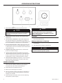
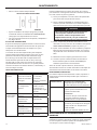
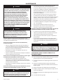
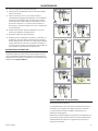
AIR FILTER MAINTENANCE
In order to ensure optimum compressed air quality the lter
element should be replaced as follows. (Used lter elements
must be disposed of in accordance with local regulations.)
1)
2)
3)
4)
5)
6)
Use only genuine Ingersoll Rand replacement elements.
1
2
2
3
> 30s
4
5
0 bar
0 psi
1
2
0 bar
0 psi
7 8
0 bar
0 psi
9 10
2
1
0 bar
0 psi
0 bar
0 psi
1
2
12
5 6
1
71113.13.16

14 80447113 Rev.A
MAINTENANCE
DISASSEMBLING THE UNIT
The unit has been designed and constructed to guarantee
continuous operation.
The long service life of some components such as the fan and
compressor depends on good maintenance.
The unit must only be disassembled by a refrigerant
specialist.
Refrigerant liquid, refrigeration components and lubricating
oil inside the refrigeration circuit must be recovered in
compliance with current norms in the country where the
machine is installed.
RECYCLING DISASSEMBLY
Frame and panels Steel / epoxy resin polyester
Heat exchanger (cooler) Stainless steel
Pipes Copper
Insulation Gum synthetic
Compressor Steel / copper / aluminium / oil
Condenser Aluminium
Refrigerant R134a
Valve Steel
REFRIGERANT LEAKS IN THE REFRIGERATION
CIRCUIT
The unit is despatched in perfect working order, already
charged.
Refrigerant leaks may be identied by tripping of the
refrigeration overload protector .
IF A LEAK IS DETECTED IN THE REFRIGERANT CIRCUIT, SEEK TECHNICAL
ASSISTANCE.
REFRIGERANT CHARGING
This operation must only be performed by a refrigerant
specialist.
WHEN REPAIRING THE REFRIGERANT CIRCUIT, COLLECT ALL
THE REFRIGERANT IN A CONTAINER AND DISPOSE OF IT IN THE
APPROPRIATE MANNER.
CHARACTERISTICS OF REFRIGERANT R134A
In normal temperature and pressure conditions the above
refrigerant is a colorless, class A1/A1 gas with TVL value of
1000ppm (ASHRAE classication).
If a refrigerant leak occurs, thoroughly air the room before
commencing work.
TROUBLESHOOTING
TROUBLE CAUSE ACTION
Solenoid
condensate
valve will not
close
1. Debris in
solenoid valve
prevents
diaphragm from
seating.
1. Remove solenoid
valve, disassemble,
clean and
reassemble.
2. Short in
electrical
components.
2. Check and
replace power cord
or timer as needed.
Drain timer will
not operate
1. No electrical
supply.
1. Apply power.
2. Timer
malfunction.
2. Replace timer.
3. Clogged port. 3. Clean valve.
4. Solenoid valve
malfunction.
4. Replace solenoid
valve.
5. Clogged
strainer.
5. Clean strainer.
MAINTENANCE
Periodically clean the screen inside the valve to keep the
drain functioning at maximum capacity. To do this, perform
the following steps:
Close the strainer ball valve completely to isolate it
from the air receiver tank.
Press the TEST button on the timer to vent the pressure
remaining in the valve. Repeat until all pressure is
removed.
CAUTION
High pressure air can cause injury from ying debris.
Ensure the strainer ball valve is completely closed and
pressure is released from the valve prior to cleaning.
Remove the plug from the strainer with a suitable
wrench. If you hear air escaping from the cleaning port,
STOP IMMEDIATELY and repeat steps I and 2.
Remove the stainless steel lter screen and clean it.
Remove any debris that may be in the strainer body
before replacing the lter screen.
Replace plug and tighten with wrench.
When putting the Electric Drain Valve back into service,
press the TEST button to conrm proper function.
1)
2)
3)
4)
5)
6)
71113.13.16

80447113 Rev.A 15
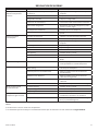
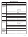
TROUBLE SHOOTING
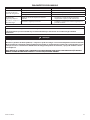
PROBLEM CAUSE REMEDY
Compressor fails to start Mains power or Control voltage not
available.
§ Check incoming power supply.
§ Check the control circuit fuse.
§ Check the transformer secondary windings
for the controlvoltage.
Defective Star / Delta timer. § Change Star / Delta timer.
Machine shuts down
periodically
High airend temperature. Top up coolant.
Motor overload. § Set overload to correct value and switch to
manual reset.
Line voltage variation. § Ensure voltage does not drop below 10%
on start up and 6% running.
High current draw Compressor operating aboverated pressure. Set pressure to correct rating for machine.
Separator cartridge contaminated. Change air lter, and separator element.
Low voltage. § Ensure voltage does not drop below 10%
on start up and 6% running.
Unbalanced voltage. Correct incoming supply voltage.
Damaged airend. † Change Airend.
Low current draw Air lter contaminated. Change air lter.
Compressor operating unloaded. Set pressure to correct rating for machine.
High voltage. Reduce site voltage to correct operating
voltage.
Defectiveinlet valve. † Fit inlet valve service kit.
High discharge pressure Defective or incorrect pressure switch
setting.
Replace or set pressure to correct rating for
machine.
Blowdown valve defective. † Fit blowdown solenoid service kit.
Inlet valvemalfunction. † Fit inlet valve service kit.
Low system air pressure Separator cartridge contaminated. Fit new Separator element.
Incorrect pressure transducer setting Set pressure to correct rating for machine.
Minimum pressure valvemalfunction. † Fit Minimum pressure valve service kit.
Blowdown valve defective. † Fit blowdown solenoid service kit.
Drivebeltslipping. Fit new belt.
Air system leaks. † Fixleaks.
Inlet valvemalfunction. † Fit inlet valve service kit.
System demand exceeds compressor
delivery.
Reduce demand or install additional
compressor.
Compressed air lters contaminated. Replace air lter elements.
High dewpoint Refrigeration compressor not supplied
power.
Check incoming power supply.
Check the dryer protection fuse.
Check auxiliary contact on main motor
contactor.
Condensate system malfunction. Check operation of drain valve.
Check operation of condensate check
valves.
Condenser dirty. Clean condenser and replace panellter
element.
Ice formation in dryer Low evaporator pressure. Check hot gas valve setting.
71113.13.16

16 80447113 Rev.A
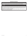
TROUBLE SHOOTING
PROBLEM CAUSE REMEDY
Compressor trips due to over
temperature
Compressor operating above rated
pres-sure.
Set pressure to correct rating for machine.
Package pre–lter blocked. Clean / replace package pre–lter.
Cooler blocked. Clean cooler.
Missing or incorrectly tted enclosure
panels
Ensure that all enclosure panels are
correctly tted.
Low coolant level. Top up coolant and check for leaks.
High ambient temperature. Re–site compressor.
Restricted cooling air ow. Ensure correct air ow to compressor.
Excessive coolant consumption Separator element leak. Fit new Separator element.
Blocked separator element drain. † Remove ttings and clean.
Compressor operating below rated
pres-sure.
Set pressure to correct rating for machine.
Coolant system leak. † Fixleaks.
Excessive noise level Air system leaks. † Fixleaks.
Airend defective. † Change Airend.
Belts Slipping. Replace belt and tensioner.
Motor defective. † Replace motor.
Loose components. † Retighten loose items.
Shaft seal leaking Defective shaft seal. † Fit Airend shaft seal kit.
Pressure relief valve opens Defective switch or incorrect pressure
switch setting.
Replace or set pressure to correct rating for
machine.
Minimum pressure valvemalfunction. † Fit Minimum pressure valve service kit.
Blowdown valve defective. † Fit blowdown solenoid service kit.
Inlet valvemalfunction. † Fit inlet valve service kit.
Pressure relief valve defective. Check the setting of the pressure relief
valve and the rated pressure.
Black residue on belt guard/
cooler box
Drivebeltslipping. Replace belt and tensioner.
Pulleys misaligned. Re–align pulleys.
Worn pulleys. † Replace pulleys and belt.
Safety valve blows when
compressor goes on load
Minimum pressure valve stuck closed. Strip minimum pressure valve, examine
and repair if necessary.
Safety valve faulty Check the setting of the safety valve and
the rated pressure.
NOTE
§ Must be carried out by a competent electrician.
† This work is recommended to be carried out only by an Ingersoll Rand authorized service technician.
CAUTION
LOW DEMAND APPLICATIONS
During periods of low demand, the compressor may not reach its normal operating temperature. Sustained
operation at low demand can result in the build up of condensate in the coolant. If this situation occurs, the
lubricating characteristics of the coolant can be impaired which may lead to damage of the compressor.
THE COMPRESSOR SHOULD BE ALLOWED AMPLE LOADED RUNNING TIME OF AT LEAST 10 MINUTES PER HOUR
DURING NORMAL DAILY USE.
71113.13.16

71113.13.16

71113.13.16

71113.13.16

ingersollrandproducts.com
© 2013 Ingersoll-Rand, plc
71113.13.16
A página está carregando...
A página está carregando...
A página está carregando...
A página está carregando...
A página está carregando...
A página está carregando...
A página está carregando...
A página está carregando...
A página está carregando...
A página está carregando...
A página está carregando...
A página está carregando...
A página está carregando...
A página está carregando...
A página está carregando...
A página está carregando...
A página está carregando...
A página está carregando...
A página está carregando...
A página está carregando...
A página está carregando...
A página está carregando...
A página está carregando...
A página está carregando...
A página está carregando...
A página está carregando...
A página está carregando...
A página está carregando...
A página está carregando...
A página está carregando...
A página está carregando...
A página está carregando...
A página está carregando...
A página está carregando...
A página está carregando...
A página está carregando...
A página está carregando...
A página está carregando...
A página está carregando...
A página está carregando...
A página está carregando...
A página está carregando...
A página está carregando...
A página está carregando...
A página está carregando...
A página está carregando...
A página está carregando...
A página está carregando...
A página está carregando...
A página está carregando...
A página está carregando...
A página está carregando...
A página está carregando...
A página está carregando...
A página está carregando...
A página está carregando...
A página está carregando...
A página está carregando...
A página está carregando...
A página está carregando...
-
 1
1
-
 2
2
-
 3
3
-
 4
4
-
 5
5
-
 6
6
-
 7
7
-
 8
8
-
 9
9
-
 10
10
-
 11
11
-
 12
12
-
 13
13
-
 14
14
-
 15
15
-
 16
16
-
 17
17
-
 18
18
-
 19
19
-
 20
20
-
 21
21
-
 22
22
-
 23
23
-
 24
24
-
 25
25
-
 26
26
-
 27
27
-
 28
28
-
 29
29
-
 30
30
-
 31
31
-
 32
32
-
 33
33
-
 34
34
-
 35
35
-
 36
36
-
 37
37
-
 38
38
-
 39
39
-
 40
40
-
 41
41
-
 42
42
-
 43
43
-
 44
44
-
 45
45
-
 46
46
-
 47
47
-
 48
48
-
 49
49
-
 50
50
-
 51
51
-
 52
52
-
 53
53
-
 54
54
-
 55
55
-
 56
56
-
 57
57
-
 58
58
-
 59
59
-
 60
60
-
 61
61
-
 62
62
-
 63
63
-
 64
64
-
 65
65
-
 66
66
-
 67
67
-
 68
68
-
 69
69
-
 70
70
-
 71
71
-
 72
72
-
 73
73
-
 74
74
-
 75
75
-
 76
76
-
 77
77
-
 78
78
-
 79
79
-
 80
80


Ingersoll-Rand UP6 5 Installation, Operation and Maintenance Manual
- Tipo
- Installation, Operation and Maintenance Manual
em outras línguas
- español: Ingersoll-Rand UP6 5
- français: Ingersoll-Rand UP6 5
- English: Ingersoll-Rand UP6 5
Artigos relacionados
-
Ingersoll-Rand HP50-PE Manual do usuário
-
-
-
-
-
-
-
-
-