
80448418
Revision C
June 2016
Save These Instructions
Contact-Cooled Rotary Screw Air Compressor
Installation, Operation and Maintenance
UP5S 11, UP5S 15, UP5S 18, UP5S 22
UP6S 15, UP6S 20, UP6S 25, UP6S 30
Installation, Operation and Maintenance
EN
RELEASED 20/Jul/2016 17:56:55 GMT

2 80448418 Rev.C
CONTENTS
FOREWORD . . . . . . . . . . . . . . . . . . . . . . . . . . . . . . . . . . 3
SAFETY . . . . . . . . . . . . . . . . . . . . . . . . . . . . . . . . . . . . . . 4
INSTALLATION / Handling . . . . . . . . . . . . . . . . . . . . . 5
LOCATION IN THE PLANT . . . . . . . . . . . . . . . . . . . . . . . . . . . . . .5
DISCHARGE PIPING . . . . . . . . . . . . . . . . . . . . . . . . . . . . . . . . . . . .5
OPERATING INSTRUCTIONS . . . . . . . . . . . . . . . . . . . 7
GENERAL OPERATION . . . . . . . . . . . . . . . . . . . . . . . . . . . 7
OPERATING INSTRUCTIONS (XE-70M
CONTROLLER) . . . . . . . . . . . . . . . . . . . . . . . . . . . . . . . . 8
USER INTERFACE . . . . . . . . . . . . . . . . . . . . . . . . . . . . . . . 8
LED STATUS ICONS . . . . . . . . . . . . . . . . . . . . . . . . . . . . . . . . . . . .8
COMMAND KEYS . . . . . . . . . . . . . . . . . . . . . . . . . . . . . . . . . . . . . .8
NAVIGATION KEYS . . . . . . . . . . . . . . . . . . . . . . . . . . . . . . . . . . . . .8
DISPLAY LAYOUT . . . . . . . . . . . . . . . . . . . . . . . . . . . . . . . . . . . . . .8
FOLDER NAVIGATION AND ICONS . . . . . . . . . . . . . . . . . . . . . .9
PAGE NAVIGATION. . . . . . . . . . . . . . . . . . . . . . . . . . . . . . . . . . . . .9
ACCESSING PARAMETERS . . . . . . . . . . . . . . . . . . . . . . . . . . . . . .9
DASHBOARD ICONS . . . . . . . . . . . . . . . . . . . . . . . . . . . . . . . . . . .9
DASHBOARD STATUS MESSAGES . . . . . . . . . . . . . . . . . . . . . 10
FIXED SPEED COMPRESSOR . . . . . . . . . . . . . . . . . . . .10
HOME FOLDER . . . . . . . . . . . . . . . . . . . . . . . . . . . . . . . . . . . . . . 10
OPERATOR SETTINGS FOLDER . . . . . . . . . . . . . . . . . . . . . . . 11
EVENTS FOLDER . . . . . . . . . . . . . . . . . . . . . . . . . . . . . . . . . . . . . 14
TRIP HISTORY . . . . . . . . . . . . . . . . . . . . . . . . . . . . . . . . . . . . . . . 17
MAINTENANCE FOLDER . . . . . . . . . . . . . . . . . . . . . . . . . . . . . 17
GENERAL SETTINGS FOLDER . . . . . . . . . . . . . . . . . . . . . . . . . 17
INTEGRAL SEQUENCING FOLDER . . . . . . . . . . . . . . . . . . . . . 19
STATUS FOLDER . . . . . . . . . . . . . . . . . . . . . . . . . . . . . . . . . . . . . 20
FACTORY SETTINGS FOLDER . . . . . . . . . . . . . . . . . . . . . . . . . 22
MAINTENANCE . . . . . . . . . . . . . . . . . . . . . . . . . . . . . . 24
TOP UP COOLANT PROCEDURE . . . . . . . . . . . . . . . . . . . . . . 25
COOLANT CHANGE PROCEDURE . . . . . . . . . . . . . . . . . . . . . 25
COOLANT FILTER CHANGE PROCEDURE . . . . . . . . . . . . . . 26
AIR FILTER ELEMENT CHANGE PROCEDURE . . . . . . . . . . . 26
SEPARATOR CARTRIDGE CHANGE PROCEDURE . . . . . . . 26
COOLER CLEANING PROCEDURE . . . . . . . . . . . . . . . . . . . . . 26
BELT CHANGE / GAS STRUT CHANGE PROCEDURE . . . . 27
ELECTRIC DRAIN VALVE - OPERATION AND
MAINTENANCE . . . . . . . . . . . . . . . . . . . . . . . . . . . . . . 28
PRODUCT DESCRIPTION . . . . . . . . . . . . . . . . . . . . . . . . . . . . . 28
OPERATION . . . . . . . . . . . . . . . . . . . . . . . . . . . . . . . . . . . . . . . . . 28
TIMER SETTINGS . . . . . . . . . . . . . . . . . . . . . . . . . . . . . . . . . . . . 28
TROUBLESHOOTING . . . . . . . . . . . . . . . . . . . . . . . . . . . . . . . . . 28
MAINTENANCE . . . . . . . . . . . . . . . . . . . . . . . . . . . . . . . . . . . . . . 28
DRYER OPTION - OPERATION AND
MAINTENANCE . . . . . . . . . . . . . . . . . . . . . . . . . . . . . . 29
INSTALLATION . . . . . . . . . . . . . . . . . . . . . . . . . . . . . . . . . . . . . . . 29
ELECTRICAL CONNECTION . . . . . . . . . . . . . . . . . . . . . . . . . . . 29
CONDENSATE DRAINS . . . . . . . . . . . . . . . . . . . . . . . . . . . . . . . 29
START–UP AND OPERATION . . . . . . . . . . . . . . . . . . . . . . . . . . 29
STOPPING THE DRYER . . . . . . . . . . . . . . . . . . . . . . . . . . . . . . . 29
OPERATION . . . . . . . . . . . . . . . . . . . . . . . . . . . . . . . . . . . . . . . . . 29
MAINTENANCE . . . . . . . . . . . . . . . . . . . . . . . . . . . . . . . . . . . . . . 30
MOISTURE SEPARATOR MAINTENANCE . . . . . . . . . . . . . . . 30
AIR FILTER MAINTENANCE . . . . . . . . . . . . . . . . . . . . . . . . . . . 30
DISASSEMBLING THE UNIT . . . . . . . . . . . . . . . . . . . . . . . . . . . 31
REFRIGERANT LEAKS IN THE REFRIGERATION CIRCUIT . 31
REFRIGERANT CHARGING . . . . . . . . . . . . . . . . . . . . . . . . . . . . 31
CHARACTERISTICS OF REFRIGERANT R134A . . . . . . . . . . 31
TROUBLE SHOOTING . . . . . . . . . . . . . . . . . . . . . . . . . 32
RELEASED 20/Jul/2016 17:56:55 GMT

80448418 Rev.C 3
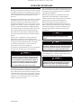
FOREWORD
The contents of this manual are considered to be
proprietary and condential to Ingersoll Rand and
should not be reproduced without the prior written
permission of Ingersoll Rand.
Nothing contained in this document is intended to
extend any promise, warranty or representation,
expressed or implied, regarding the Ingersoll Rand
products described herein. Any such warranties or other
terms and conditions of sale of products shall be in
accordance with the standard terms and conditions of
sale for such products, which are available upon request.
This manual contains instructions and technical data to
cover routine operation and scheduled maintenance tasks
by operation and maintenance sta. Major overhauls are
outside the scope of this manual and should be referred
to an authorized Ingersoll Rand service department.
All components, accessories, pipes and connectors added
to the compressed air system should be:
of good quality, procured from are putable manufac-
turer and, wherever possible, be of a type approved
by Ingersoll Rand.
clearly rated for a pressure atleast equal to the
machine maximum allowable working pressure.
compatible with the compressor lubricant/coolant.
accompanied with instructions for safe installation,
operation and maintenance.
Details of approved equipment are available from
Ingersoll Rand Service departments.
The use of non–genuine spare repair parts other than
those included within the Ingersoll Rand approved
partslist may create hazardous conditions over which
Ingersoll Rand has no control. Therefore
Ingersoll Rand does not accept any liabilitity for losses
caused by equipment in which non–approved repair
parts are installed. Standard warranty conditions may be
aected.
Ingersoll Rand reserves the right to make changes and
improvements to products without notice and without
incurring any obligation to make such changes or add
such improvements to products sold previously.
The intended uses of this machine are outlined below and
examples of unapproved usage are also given, however
Ingersoll Rand cannot anticipate every application or
work situation that may arise.
•
•
•
•
IF IN DOUBT CONSULT SUPERVISION.
This machine has been designed and supplied for
use only in the following specied conditions and
applications:
Compression of normal ambient air containing no
known or detectable additional gases, vapors or
particles.
Operation within the ambient temperature range
specied in the Product specication sheet.
The use of the machine in any of the situation types
listed in
Is not approved by Ingersoll Rand,
May impair the safety of users and other persons,
and
May prejudice any claims made against
Ingersoll Rand.
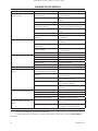
TABLE 1
Use of the machine to produce compressed air for:
direct human consumption
indirect human consumption, without suitable
ltration and purity checks.
a)
b)
Use of the machine outside the ambient temperature
range specied in the Product specication sheet.
Use of the machine where there is any actual or
foreseeable risk of hazardous levels of ammable gases
or vapors.
THIS MACHINE IS NOT INTENDED AND MUST NOT BE
USED IN POTENTIALLY EXPLOSIVE ATMOSPHERES,
INCLUDING SITUATIONS WHERE FLAMMABLE GASES OR
VAPORS MAY BE PRESENT.
Use of the machine tted with non Ingersoll Rand
approved components.
Use of the machine with safety or control components
missing or disabled.
The company accepts no responsibility for errors in
translation of this manual from the original English
version.
•
•
a)
b)
c)
RELEASED 20/Jul/2016 17:56:55 GMT

4 80448418 Rev.C
SAFETY
Locate, read, understand and follow all Danger, Warning,
Caution, and Operating Instructions on the product and
in all Manuals. Failure to comply with safety precautions
described in the manuals supplied with the product,
this manual or any of the labels and tags attached to the
product may result in death, serious injury or property
damage.
Check that all labels, tags and data (name) plates are in
place and legible.
It is your responsibility to make this information available
to others.
If you have any questions about safety or procedures not
included in this manual, ask your supervisor or contact
any Ingersoll Rand oce or qualied Ingersoll Rand
distributor.
RELEASED 20/Jul/2016 17:56:55 GMT

80448418 Rev.C 5
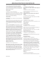
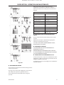
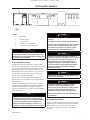
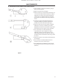
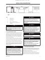
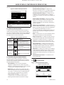
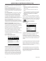
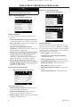
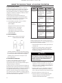
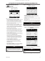
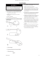
INSTALLATION / HANDLING
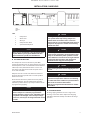
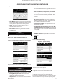
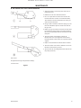
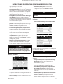
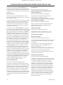
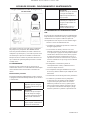
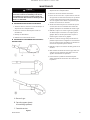
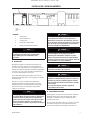
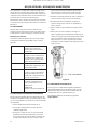
1
KEY
1 Compressor
2 Air Receiver
3 Air Dryer
4 Compressed air lters
5 System demand points
NOTICE
Items [2] to [5] are optional or may be existing items
of plant. Refer to your Ingersoll Rand distributor /
representative for specic recommendations.
LOCATION IN THE PLANT
The compressor can be installed on any level oor
capable of supporting it. A dry, well ventilated area where
the atmosphere is clean is recommended. A minimum of
150 mm (6 inches) should be left at the rear and 1 m
(3 ft) at the sides of the machine for adequate service
access and ventilation.
Adequate clearance needs to be allowed around and
above the machine to permit safe access for specied
maintenance tasks.
Ensure that the machine is positioned securely and on
a stable foundation. Any risk of movement should be
removed by suitable means, especially to avoid strain on
any rigid discharge piping.
NOTICE
The Main Motor Overload Current set point is preset
into the compressor controller program before
leaving the factory and is not user adjustable. If this
is required to be changed, due to an input voltage
conversion, contact your local Ingersoll Rand service
provider.
CAUTION
Screw type compressors [1] should not be installed
in air systems with reciprocating compressors
without means of isolation such as a common
receiver tank. It is recommended that both types of
compressor be piped to a common receiver using
individual air lines.
CAUTION
The use of plastic bowls on line lters and other
plastic air line components can be hazardous. Their
safety can be aected by either synthetic coolants
or the additives used in mineral oils. Ingersoll Rand
recommends that only lters with metal bowls
should be used on any pressurised system.
CAUTION
Before starting machine remove shipping bolt and
discard.
CAUTION
The standard compressor unit is not suitable for
operation in temperatures liable to cause freezing
as condensate water is liable to be produced in the
after cooler and receiver where tted.
Refer to your Ingersoll Rand distributor for further
information.
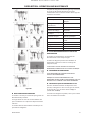
DISCHARGE PIPING
Discharge piping should be at least as large as the
discharge connection of the compressor. All piping
and ttings should be suitably rated for the discharge
pressure.
RELEASED 20/Jul/2016 17:56:55 GMT

6 80448418 Rev.C
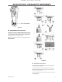
INSTALLATION / HANDLING
It is essential when installing a new compressor [1],
to review the total air system. This is to ensure a safe
and eective total system. One item which should be
considered is liquid carryover. Installation of air
dryers [3] is always good practice since properly selected
and installed they can reduce any liquid carry over to
zero.
It is good practice to locate an isolation valve close to the
compressor and to install line lters [4].
RELEASED 20/Jul/2016 17:56:55 GMT

80448418 Rev.C 7
OPERATING INSTRUCTIONS
GENERAL OPERATION
The compressor is an electric motor driven, single stage
screw compressor, complete with accessories piped,
wired and baseplate mounted. It is a totally self contained
air compressor package.
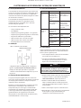
The standard compressor is designed to operate in an
ambient range of 35.6 °F – 104 °F (2 °C to 40 °C) with a
special option package available to operate in ambient
temperatures ranges from 35.6 °F up to124 °F (2 °C up to
50 °C). The maximum temperature is applicable to either
version up to a maximum elevation of 3280 ft (1000 m)
above sea level. Above this altitude signicant reduction
in maximum allowable ambient temperature is required.
Compression in the screw type air compressor is created
by the meshing of two (male & female) helical rotors.
The air/coolant mixture discharges from the compressor
into the separation system. This system removes all but
a few PPM of the coolant from the discharge air. The
coolant is returned to the cooling system and the air
passes through the aftercooler and out of the compressor.
Cooling air is moved through the coolers by the cooling
fan and discharged from the machine.
CAUTION
Cooling air is drawn in at the end of the machine
package passing through the lter and cooler
before being discharged from the top of the
machine. Care should be taken to avoid blocking the
airow, or causing any restriction in excess of the
maximum backpressure allowed for ducting.
Do not direct the airow at face or eyes.
The power transmission from the drive motor to the
airend male rotor is by pulley and belts. The constant
auto tensioning system, using airend mass torque and
gas arm, ensures that the belts are always under the
correct tension, eliminating the need for adjustment and
maximizing the life of the belts.
By cooling the discharge air, much of the water vapor
naturally contained in the air is condensed and may be
drained from the downstream piping and equipment.
The coolant system consists of a sump, cooler,
thermostatic valve and a lter. When the unit is operating,
the coolant is pressurized and forced to the compressor
bearings.The compressor load control system is
automatic on–o line.
The compressor will operate to maintain a set discharge
line pressure and is provided with an auto restart
system for use in plants where the air demand varies
suciently to allow a compressor to shut down and save
power. Signicant system volume will assist this and is
recommended.
NOTICE
Not all Xe-70 Controller options available on this
compressor model (UP Series).
WARNING
When the unit stops running as the result of low air
demand, normally indicated by auto restart light, it
may restart and return to load at any time.
Safety of operation is provided as the compressor will
shut down if excessive temperatures or electrical overload
conditions should occur.
CAUTION
This unit is not designed or intended to operate
when contaminated with silicone. Lubricants,
greases or other items containing silicone should
not be used on this unit.
RELEASED 20/Jul/2016 17:56:55 GMT

8 80448418 Rev.C
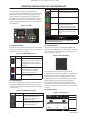
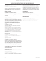
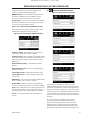
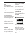
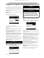
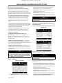
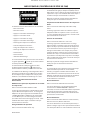
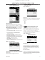
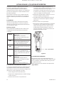
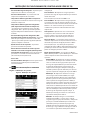
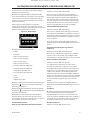
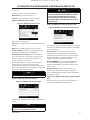
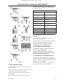
OPERATING INSTRUCTIONS XE70M CONTROLLER
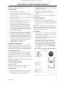
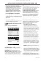
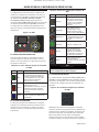
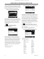
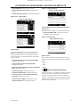
USER INTERFACE
The standard user interface conguration of the
controller consists of the membrane and the LCD display.
The membrane consists of ve command keys (Start,
Stop, Load, Unload, and Reset), four navigation keys
(Up, Right, Left and Down), and an Edit mode selection
key (Enter). These keys, in conjunction with the graphics
display and the LED icons, make up the user interface to
the compressor.
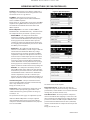
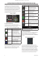
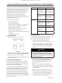
Figure 1: Xe-70M
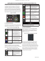
LED STATUS ICONS
Three LED icons are used to indicate the current status of
the control system from a distance and are located on the
upper left side of the user interface.
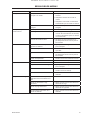
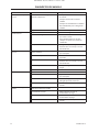
Table 1: Xe-70M LED Status Icons
Icon Name Function
OK Illuminates when no Warnings or
Trips are sensed. Can be in a Ready
or Not Ready state. This icon will
ash when the machine is Running
Unloaded.
Alert Illuminates when a Warning
(ashes) or Trip (constant ON)
is sensed. Can be in a Ready
(Warning) or Tripped state.
Auto Illuminates when the compressor
stops in auto restart.
COMMAND KEYS
These keys command the controller to perform actions as
specied in the following table. When any of these keys
are pressed the action below will be initiated and logged
in the event log.
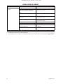
Table 2: Xe-70M Command Keys
Icon Name Function
Load Puts the compressor into the
selected mode of operation.
Unit will load if the pressure
conditions are right.
Unload Puts the compressor into an
unloaded state. Unit will run
unloaded indenitely.
Icon Name Function
Reset Clears Warnings and Trips once
the fault condition is corrected.
Start Starts the compressor.
Stop Stops the compressor. This
button should be pressed
instead of the Emergency Stop
for normal stopping operation.
Enter Toggles the display between the
Navigation mode and the Edit
mode.
NOTICE
The Load and Unload keys are not used on the
variable speed compressors.
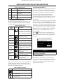
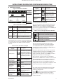
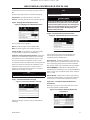
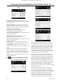
NAVIGATION KEYS
There are four navigation keys (UP, RIGHT, DOWN and
LEFT). While the ENTER key is not considered a navigation
key, it is used in conjunction with the navigation keys to
make or conrm a selection.
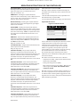
Figure 2 : Navigation Keys
The navigation keys roll over. Pressing one of the
navigation keys will lead the user down a navigation path.
Each time the key is pressed, another step in the path
is taken. Once the end of a navigation path is reached,
pressing the key one more time will bring the user back
to the beginning of the path. Pressing the opposite
key will move the user through the navigation path in
the opposite direction. Once the beginning is reached,
pressing the opposite key will take the user to the end of
the path.
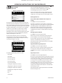
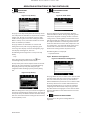
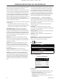
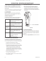
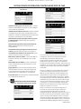
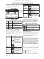
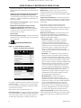
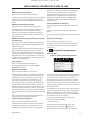
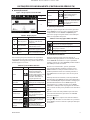
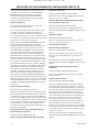
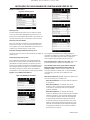
DISPLAY LAYOUT
Figure 3 : Display Layout
A
B
C
D
RELEASED 20/Jul/2016 17:56:55 GMT

80448418 Rev.C 9
Table 3 : Display Layout
Key Name Description
A Folder Bar Uses tabs to graphically identify
each folder.
B Title Bar Identies current folder and page
(underlined).
C Page
Content
Content of the current page.
D Dashboard Displays system status.
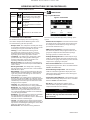
FOLDER NAVIGATION AND ICONS
To move among the tabbed folders shown on the LCD
display, press the RIGHT and LEFT keys. The navigation
rolls over from the last to the rst folder and vice-versa.
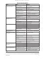
Table 4 : Folder Bar Icons
Folder
Name
Icon Description
Home
System performance and status
main information. The rst page
of this folder is the default page
when the controller rst powers
up.
Operator
Settings
System options and
conguration settings.
Events System events log.
Trip History
Details on the most recent trips.
Maintenance Status and notication setup for
compressor maintenance items.
General
Settings
General settings such as
Language, Time, and Units of
Measure.
Integral
Sequencing
Integral Sequencing
communication status and
conguration.
Status Measurements or status from/of
all analog and digital I/O.
Factory
Settings
Compressor tuning parameters.
Also displays hardware and
software versions.
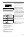
PAGE NAVIGATION
Once the desired folder is selected, press the DOWN key
to move to the page selection area and then use the
RIGHT and LEFT keys to select the desired page. Use the
UP key to get back to the folder tabs.
Table 5 : Title Bar Page Icons
Icon Description
Start of the page selection area.
Indicates that there are more pages available
by navigating right.
Indicates that there are more pages available
by navigating left.
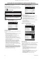
ACCESSING PARAMETERS
After the desired page is selected, the page’s parameters
can be selected by using the DOWN key. The cursor will
move to the next parameter each time the DOWN key is
pressed. Use the UP key to go back to the previous one.
The cursor rolls over, so once the last parameter is
selected, pressing the DOWN key will navigate the
cursor to the Folder Bar. If the rst parameter is selected,
pressing the UP key will move the cursor to the page
selection area.
Once selected, access parameters by pressing the ENTER
key. Make changes using the NAVIGATION keys and then
enter the setting by pressing the ENTER key again. After a
parameter is accessed, pressing the ENTER key will enter
the current setting into the control program and navigate
the cursor back to the selected parameter on the page.
When the cursor is on a parameter that has an enabled/
disabled box, pressing the ENTER key will cause the
setting to toggle.
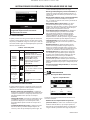
This icon appears on numeric entry windows (see
Figure 69). Placing the cursor on it and then pressing the
ENTER key will cancel the entry and any changes that
were made.
Figure 4 : Numeric Entry Window
NOTICE
Not all pages have adjustable parameters. Some just
have read-only information.
DASHBOARD ICONS
The dashboard is intended to be a quick at-a-glance
view of system status. The following table lists standard
dashboard icons and their denition. Note that the color
of these icons changes based on the state set by the
application while running.
OPERATING INSTRUCTIONS XE70M CONTROLLER
RELEASED 20/Jul/2016 17:56:55 GMT

10 80448418 Rev.C
Table 6 : Dashboard Icons
Name Icon Description
Remote
Control
Remote control is enabled. This
can be Remote Start/Stop, COM
Control, Integral Sequencing or
Web Control.
Service
Required
A service reminder is nearing or
has expired
(i.e.: an air or oil lter needs to be
changed).
Unloaded
or
Loaded
Compressor is in the unloaded
state.
Compressor is in the loaded state.
DASHBOARD STATUS MESSAGES
The dashboard also displays the current operating
state of the compressor. The following states can be
encountered during machine operation:
Ready to Start – The compressor currently has no trip
or start inhibit conditions present. The machine can be
started by pressing the start button at any time.
Starting – A start command has been given to
the compressor and the start sequence is being
performed. The time period for this state can vary
depending on the starter type of the machine.
Load Delay – The compressor is waiting for a small
period of time after starting before allowing the
machine to load. This ensures the machine is at
operating conditions before loading.
Running Loaded – The compressor is operating and
producing air. The inlet valve is open and the blow-o
valve is closed.
Running Unloaded – The compressor is operating,
but not producing air. The inlet valve is closed and the
blow-o valve is open.
Reload Delay – This is a brief period of time after the
compressor has unloaded before it is allowed to load
again. This gives the inlet and bypass valves time to
reach their proper positions.
Auto-Restart – The compressor has stopped due to
pressure rising above the oine or auto-stop setpoints
and auto-restart being enabled. The compressor will
automatically restart when pressure falls to the online
or target pressure setpoint.
Stopping – The compressor has received a stop
command and the stop sequence is being performed.
Blowdown – The compressor must wait for a brief
period of time after stopping its motor before it is
allowed to start again. The compressor will restart at
the end of the blowdown period if a start command is
recieved during blowdown.
Not Ready – The compressor has detected a condition
that will not allow the compressor to start. The
condition must be cleared before a start is allowed, but
does not need to be acknowledged.
Tripped – The compressor has detected an abnormal
operational condition that has stopped the machine. A
trip must be acknowledged by hitting the reset button
before the compressor can start.
Processor Init – The controller is being initialized.
•
•
•
•
•
•
•
•
•
•
•
•
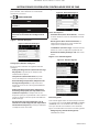
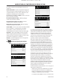
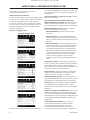
FIXED SPEED COMPRESSOR
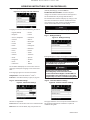
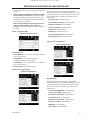
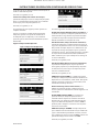
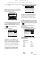
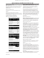
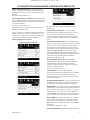
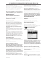
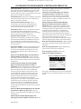
HOME FOLDER
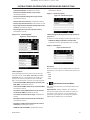
Page 1: System Overview
Figure 5 : Home Folder
This is the factory default display after powering up the
system.
Online Pressure Setpoint - indicated in the black box
and arrow, which is always left of center on the gauge.
The compressor will load when package discharge
pressure falls below this value.
Oine Pressure Setpoint - indicated in the black
box and arrow, which is always right of center on the
gauge. The compressor will unload when package
discharge pressure rises above this value.
Package Discharge Pressure - indicated by the large
numbers centered below the gauge and by the black
arrow below the gauge. This is the air pressure that the
compressor is supplying to the plant.
Pressure Unit of Measure - indicated below the
Package Discharge Pressure. This is selectable from the
GENERAL SETTINGS folder.
Airend Discharge Temperature - indicated by the
numbers in the lower right of the display. This is the
temperature of the air/oil mixture at the discharge of
the compression module.
Temperature Unit of Measure - indicated to the right
of the Airend Discharge Temperature. This is selectable
from the GENERAL SETTINGS folder.
Run Hours – indicated by the numbers in the
lower left of the display. The number of hours the
compressor motor has been running.
NOTICE
The online and oine set points can be selected and
modied on this page. All other information on this
page is read only.
•
•
•
•
•
•
•
OPERATING INSTRUCTIONS XE70M CONTROLLER
RELEASED 20/Jul/2016 17:56:55 GMT

80448418 Rev.C 11
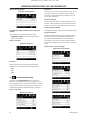
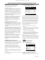
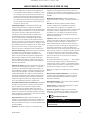
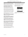
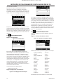
Page 2 : Counters
Figure 6 : Counters
Hour Meters - Indicates the hours that: the controller
has been powered up, the compressor motor has been
running, and the compressor has running loaded.
Starts - Indicates the number of times a start is
attempted on the compressor.
Date & Time – Indicates the current date and time.
This is adjustable and congurable in the GENERAL
SETTINGS folder.
NOTICE
All information on this page is read only.
Pages 3 & 4 – Analog Inputs and Compressor
Information
Figure 7 : Analog Inputs and Compressor Information
Any sensor that is not installed or is reporting a failure will
show a [ - - ] symbol.
NOTICE
All information on this page is read only.
The following analog inputs are displayed in this section.
Package Discharge Pressure – The pressure the
compressor is delivering to the plant.
Sump Pressure – The compressor’s internal pressure at
•
•
•
•
•
the sump tank.
Airend Discharge Temperature – The temperature of
the air/oil mixture at the discharge of the compression
module.
After-cooler Discharge Temperature (Not available
on this compressor model)– The temperature of the
air after passing through the after-cooler. Note – Only
shown when the Low Ambient option is purchased and
installed.
After-cooler Discharge Pressure (Not available on
this compressor model)– Pressure the compressor is
delivering before the dryer. Note – Only shown when
the TAS option is purchased and installed.
Separator Pressure Drop – The pressure drop across
the separator element.
Dryer Run Status (Integrated dryer units only) (Not
available on this compressor model) – Checkbox that
shows whether the dryer is currently running (checked)
or not (blank).
Time and Date
Main Motor Current – Current owing through the
main motor as measured by the installed current
transducers.
OPERATOR SETTINGS FOLDER
Pages 1-2: Operator Settings
Figure 8 : Operator Settings
The below values are all setpoints
Online Pressure – The compressor will load when the
package discharge pressure falls below this value.
Range (in PSI): 65 to Oine Pressure - 10
Oine Pressure – The compressor will unload when
package discharge pressure rises above this value.
Range (in PSI): 75 to Rated Pressure + 10. Please note that
the range will be reduced by 7 psi when operating a TAS
•
•
•
•
•
•
•
OPERATING INSTRUCTIONS XE70M CONTROLLER
RELEASED 20/Jul/2016 17:56:55 GMT

12 80448418 Rev.C
machine.
Lead/Lag – When this box is checked the compressor is
operating as a lead machine. Unchecking the box causes
the machine to run as a lag machine.
Lag Oset – If the machine is running as a lag
compressor, the lag oset will be subtracted from the
online and oine setpoints.
Range (in PSI): 0 – 45, depending on the online and oine
setpoints. The Lag Oset will never allow you to exceed
the minimum or maximum values of the online and
oine setpoints.
Mode of Operation – Selections are Online/Oine,
Modulation/ACS, and Modulation only – determines how
the compressor will try to maintain a specic pressure.
Online/Oine – The compressor will load the
machine by energizing a solenoid that opens the inlet
valve and closes the blowdown valve when package
discharge pressure falls below the online pressure
setpoint. The compressor will unload the machine by
de-energizing the solenoid when pressure rises above
the oine pressure setpoint.
Modulation – The compressor will still load and
unload as in online/oine, but will energize a dierent
solenoid valve for modulation. When the package
discharge pressure is between the online and oine
setpoints the compressor will adjust the inlet valve in
order to achieve a stable output pressure. The output
pressure target needs to be set by a technician at the
inlet valve in order to provide eective modulation
control. Modulation can only work when the package
discharge pressure is above 60 psi. Modulation is an
option and must be enabled in the factory settings tab.
Mod/ACS – The compressor will initially start out in
online oine mode. If the compressor goes through 3
load/unload cycles within 3 minutes, it will switch over
into Modulation mode. It will remain in modulation
until the stop button is pressed or 3 minutes pass
between an unload and load command. Mod/ACS is an
option and must be enabled in the factory settings tab.
Unloaded Stop Time – Time period that the machine
must run unloaded before the motor is allowed to stop
after a stop command is received.
Range (in seconds): 10 - 30
Starter Time – Time period that the compressor needs
in order to come up to operating speed after a start
command before being able to produce air. Range (in
seconds): 5 - 30
The parameters on these pages are adjustable any time.
*Note that Mode of Operation can only be adjusted
if the modulation option has been purchased for the
compressor and the Enable Modulation factory setpoint
has been turned ON.
•
•
•
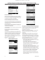
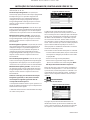
Pages 3-6: Operator Options
Figure 9 : Operator Options
The below values are all setpoints
Enable Auto-Restart – Enabling this will allow the
compressor to stop if it has been running unloaded for a
period of time, and the motor has exceeded its minimum
running time (10 minute in most cases).
Auto-Restart Time – The time period the compressor
must run unloaded before stopping in auto-restart. This
time period begins the moment that package discharge
pressure rises above the oine setpoint. Both this time
period and the minimum motor run timer (10 minutes)
must be satised before the compressor will stop in auto
restart.
Range (in seconds) 2 - 60
OPERATING INSTRUCTIONS XE70M CONTROLLER
RELEASED 20/Jul/2016 17:56:55 GMT

80448418 Rev.C 13
Auto-Restart Delay – The time period after the package
discharge pressure has fallen below the online setpoint
before the compressor can automatically restart.
Range (in seconds): 0 - 60
COM Control – Enabling this setpoint allows the
compressor to be controlled by a serial or Ethernet device,
such as an X8I. This is equivalent to the “Sequencer”
option on older Intellisys controllers.
Remote Start/Stop – Enabling this setpoint allows the
compressor to be started and stopped using the digital
inputs on the controller.
Enable PORO – Enabling this setpoint will allow the
compressor to automatically restart after a power outage
has been restored if the compressor was running loaded
at the time of the outage. PORO is an option which must
be purchased and installed before this feature can be
turned ON.
PORO Time – Time after the controller power has been
restored and controller has nished booting before the
compressor will perform a PORO start. During this time
the PORO Horn will sound.
Range (in seconds): 10 - 600
Low Ambient Temp – Temperature below which the low
ambient option will come into eect.
Range (in deg F): 30 - 60
Scheduled Start Day – Day (or days) of the week
for which a scheduled start will be performed. The
compressor will start when its onboard clock matches the
day, hour, and minute of the scheduled start setpoints.
Scheduled Start/Stop is an option which must be
purchased and installed before this feature can be turned
ON.
Scheduled Start Hour – Hour of the day for which a
scheduled start will be performed. Scheduled Start/Stop
is an option which must be purchased and installed
before this feature can be turned ON.
Scheduled Start Minute – Minute of the hour for which
a scheduled start will be performed. Scheduled Start/
Stop is an option which must be purchased and installed
before this feature can be turned ON.
Scheduled Stop Day – Day (or days) of the week
for which a scheduled stop will be performed. The
compressor will stop when its onboard clock matches the
day, hour, and minute of the scheduled stop setpoints.
Scheduled Start/Stop is an option which must be
purchased and installed before this feature can be turned
ON.
Scheduled Stop Hour – Hour of the day for which a
scheduled stop will be performed. Scheduled Start/Stop
is an option which must be purchased and installed
before this feature can be turned ON.
Scheduled Stop Minute – Minute of the hour for which
a scheduled stop will be performed. Scheduled Start/
Stop is an option which must be purchased and installed
before this feature can be turned ON.
Note that in order to disable Scheduled Start/Stop, the
Scheduled Start and Stop days, hours, and minutes must
match exactly.
* The low ambient temperature is only adjustable if the
low ambient factory set point is ON.
** A value of 0 will disable the lead/lag cycle time feature.
Page 7 Calibrate Sensors
Figure 10 : Calibrate Sensors
Sensor calibration can only take place when the machine
is stopped and there is no pressure on the sensor.
Calibration only needs to take place after a sensor
is replaced, the controller is replaced, the controller
software is upgraded, or the operator suspects the
sensor reading is in error. Calibrate a sensor by selecting
the checkbox beside the sensor name. Note that
the checkbox may appear too quickly to be visible.
Calibration can be conrmed by verifying that the sensor
value now reads zero.
Each of the sensors listed below can be calibrated.
Sump Pressure (3APT) – Only on units with the Enable
3APT factory setpoint ON.
Package Discharge Pressure (4APT)
After-cooler Discharge Pressure (7APT) – Only on units
with integrated dryer. Note : Not available on this
compressor model.
Note that if a sensor is currently reading a value that is +/-
10% of its range from zero, the sensor will not be able to
be calibrated and an warning will be logged in the event
log. Make sure the sensor is being exposed to atmosphere
before attempting calibration.
•
•
•
OPERATING INSTRUCTIONS XE70M CONTROLLER
RELEASED 20/Jul/2016 17:56:55 GMT

14 80448418 Rev.C
EVENTS FOLDER
Pages 1 to a Max of 50
Figure 11: Events folder
The pages in the Events folder document up to the last
250 events that the controller has experienced, with the
time and date of the occurrence. The events are recorded
in sequence, with number one being the newest and 250
being the oldest. When a new event occurs, it becomes
number one and all others are shifted up in number.
The page numbers in the Title Bar are used to scroll
through the events, with each page displaying up to ve.
Page one displays events one through ve, page two
displays six through ten, and so on.
The time and date of the event can be viewed by
navigating to an event and pressing the right arrow
navigation key. The time and date window can then be
exited by pressing the enter key.
Figure 12 : Events folder
The following items will generate an event.
Power ON
Power OFF
Press the Start Key
Press the Stop Key
Press the Load Key
Press the Unload Key
Starting the compressor remotely
Stopping the compressor remotely
Loading the compressor remotely
Unloading the compressor remotely
Warning
Trip
Start Inhibit
•
•
•
•
•
•
•
•
•
•
•
•
•
Active Warnings will show a ashing caution icon
while acknowledged Warnings will a solid icon.
Active Trips will show a ashing trip icon while
acknowledged Trips will have a solid icon.
Active Start Inhibits will be listed in the Event log, but
not have an icon present. The display will indicate the
compressor is not ready to start if a start inhibit is active.
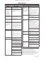
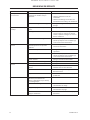
Warning Events List
Sensor Failure (Not available on this compressor
model)
Xe-70M On-Screen Text: 7ATT Failure
This will occur whenever sensor 7ATT is recognized as
missing or broken. The sensor failure message shall follow
the following format: 7ATT FAILURE. The 7ATT sensor
failure will be shown only when the integrated dryer is
installed (accessed in the factory settings menu). This
condition must exist for 3 seconds before the warning is
issued.
Change Separator Element
Xe-70M On-Screen Text: Chg Sep Elem
Will occur if the unit is loaded, the package discharge
pressure (4APT) is at least 90 psi and the separator
pressure drop is greater than 12 psi. This condition must
exist for 3 seconds before the warning is issued.
Note that the Enable 3APT setpoint must be turned ON
for this warning to occur
High Airend Discharge Temperature
Xe-70M On-Screen Text: High A/E Disch T
Will occur if the unit is running and 2ATT is greater than
221 deg F (97% of 228) and the unit is running. This
condition must exist for 3 seconds before the warning is
issued.
High Sump Pressure
Xe-70M On-Screen Text: High Sump Pres
If the unit is running loaded, has been loaded for at least 8
seconds and the sump pressure is more than 25 psi above
the rated pressure for the compressor. If this warning
occurs, the online and oine pressures will be reduced.
For example, a rated pressure of 100 psi would have a
maximum oine pressure of 110 psi. This warning would
occur if the sump pressure goes above 125 psi in this
example. This condition must exist for 3 seconds before
the warning is issued.
Note that the Enable 3APT setpoint must be turned ON
for this warning to occur.
OPERATING INSTRUCTIONS XE70M CONTROLLER
RELEASED 20/Jul/2016 17:56:55 GMT

80448418 Rev.C 15
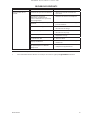
Service
Service warnings occur when the unit has operated
a certain number of hours, based on the total hours.
Service warnings can have multiple levels, depending on
the service level selection. A service level selection of 0
disables service warnings.
Service Level 1
Xe-70M On-Screen Text: SVC Required
If service level 1 has been selected for the unit, a “SERVICE
REQUIRED” warning will be issued on hour intervals equal
to the service time period set point. This warning can be
reset the same as any other warning.
Service Level 2
Xe-70M On-Screen Text: 100 hours to SVC, SVC Required,
Service Alarm
If service level 2 has been selected for the unit, the service
complete factory set point will be used to clear a level 2
service warning and reset the service time or date. The
service complete can be reset before a service warning
occurs.
The initial “SERVICE REQUIRED” warning will occur at total
hour intervals equal to the service time period set point.
However, 100 hours before this a “100 HOURS TO SERVICE”
warning will occur. This warning can be reset the same as
any other warning. One hundred hours later the “SERVICE
REQUIRED” warning will occur. This warning can be reset
the same as any other warning, however this warning
will return in 24 hours if the service complete factory set
point has not be set. If the service complete has not been
set, 100 hours later, the “ALARM – SERVICE REQUIRED”
warning will be issued. This warning can only be cleared
by the service complete factory set point. Once the
service complete factory set point is set, indicating the
service is completed, the time for the next “SERVICE
REQUIRED” warning will be calculated by adding the
service time period to the total hours value, with the “100
HOURS TO SERVICE” warning occurring 100 hours before
and the “ALARM – SERVICE REQUIRED” warning occurring
100 hours after that time.
High Discharge Pressure
Xe-70M On-Screen Text: High Disch Pres
Will occur if the unit is using a remote sensor or is under
the control of an external device, such as an X8I, is loaded,
and the discharge pressure (4APT) is greater than the
maximum oine pressure. This condition must exist for
3 seconds before the warning is issued. If this condition
occurs, the compressor will automatically unload. The unit
will be available to reload once the discharge pressure
falls to the rated pressure value.
Dryer Temp Warning (Not available on this compressor
model)
Xe-70M On-Screen Text: Dryer Temp
Dryer High Pressure (Not available on this compressor
model)
Xe-70M On-Screen Text: Dryer High Pres
Xe-70 Dryer Controls are not linked to UP Series 15-
30HP/11-22kW dryers.
Change HE Filter (Not available on this compressor
model)
Xe-70M On-Screen Text: Change HE Filt
Note that the Enable 7APT setpoint must be turned ON
for this warning to occur.
Invalid Calibration
Xe-70M On-Screen Text: Invalid Cal
Will occur if the sensor zero value is ± 10% of its scale. See
Sensor Calibration.
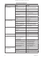
Trip Events List
Low Sump Pressure
Xe-70M On-Screen Text: Low Sump Press
Will occur if the unit is running unloaded or loaded and
3APT is less than 13 psi for 15 seconds.
Note that the Enable 3APT setpoint must be turned ON
for this warning to occur
High Airend Discharge Temperature
Xe-70M On-Screen Text: High A/E Disch T
This will occur if 2ATT is greater than 228 deg F and the
unit is running.
Check Motor Rotation
Xe-70M On-Screen Text: Ck Motor Rot
This will occur if 3APT is less than 1 psi on a unit, 3
seconds after starting (6 seconds if the unit is equipped
with a soft starter or airend discharge temperature is
less than 50 deg F). This condition can be caused by the
motor running in reverse. Once correct motor rotation
is established, this trip will not be checked again unless
power is removed from the controller. However, if correct
motor rotation is not established, this fault will be
checked after each start until correct motor rotation is
established. Correct motor rotation is established when
the controller reads a sump pressure of 1 psi or more
within 3 seconds of starting.
Note that the Enable 3APT setpoint must be turned ON
for this warning to occur.
Overload
Xe-70M On-Screen Text: Overload
This will occur if the fan or motor overload relays opens.
OPERATING INSTRUCTIONS XE70M CONTROLLER
RELEASED 20/Jul/2016 17:56:55 GMT

16 80448418 Rev.C
The contact must be open for at least 3 seconds before
the trip will occur.
Xe-70M On-Screen Text: Main Motor OL
This will occur if the current transducers indicate that
the motor amp draw is excessive. This overload is the
equivalent of a class 10A trip level.
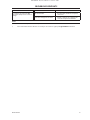
Remote Stop Failure
Xe-70M On-Screen Text: Rem Stop Fail
Will occur if the remote start/stop option is enabled, the
remote stop button remains open and either start button
is pressed.
Remote Start Failure
Xe-70M On-Screen Text: Rem Start Fail
Will occur if the remote start/stop option is enabled, the
unit is started by the remote start button, and the button
stays closed for 7 seconds after the unit starts.
Sensor Failure (Not available on this compressor
model)
Xe-70M On-Screen Text:
3APT Failure, 4APT Failure, 7APT Failure, 2ATT Failure,
Main Motor CT Failure.
This will occur when a sensor is recognized as missing
or broken. The sensors aected by this trip are CT1, CT2,
CT3, 3APT, 4APT, 7APT, and 2ATT. The sensor should be
displayed along with the sensor failure message. The
sensor failure message shall follow the following format:
3APT Failure.
Emergency Stop
Xe-70M On-Screen Text: Emergency Stop
This will occur when the EMERGENCY STOP button is
engaged.
High Sump Pressure
Xe-70M On-Screen Text: High Sump Pres
This will occur if the compressor is running loaded for at
least 8 seconds, and any one of the 3 following conditions
exist. (1) The sump pressure is above the rated pressure
by 35 psi. (2) The separator pressure drop is measured to
be more than 25 psi and the package discharge pressure
at least equal to the minimum online set point value. (3)
The sump pressure is above 165 psi if the rated pressure is
less than 190 psi or the sump pressure is above 220 if the
rated pressure is 190 psi.
Note that the Enable 3APT setpoint must be turned ON
for this warning to occur.
Unit Too Cold To Start
Xe-70M On-Screen Text: Unit Too Cold
This will occur if the unit does not have the low ambient
option, the airend discharge temperature (2ATT) is less
than 35 deg F, and the operator attempts to start the
compressor. This fault can only occur once a day. Once
this fault occurs, the operator can reset it and start the
compressor. This fault will be logged in the trip history
to indicate that the unit is being started in low ambient
conditions.
Start Inhibit List
High Airend Discharge Temperature
Xe-70M On-Screen Text: High A/E Disch T
This will occur if 2ATT is greater than 95% of 228 deg F.
High Sump Pressure
Xe-70M On-Screen Text: High Sump Pres
This will occur if the sump pressure (3APT) is 25 psi or
higher than the rated pressure of the compressor.
OPERATING INSTRUCTIONS XE70M CONTROLLER
RELEASED 20/Jul/2016 17:56:55 GMT

80448418 Rev.C 17
TRIP HISTORY
Pages 1 to a Max of 3
Figure 13 : Trip History
The pages in the Trips History folder document up to the
last 15 trips that the controller has experienced, and time
stamps each. The trips are recorded in sequence, with
number one being the newest and 15 being the oldest.
When a new trip occurs, it becomes number one and all
others are shifted up in number.
The page numbers in the Title Bar are used to scroll
through the events, with each page displaying up to
seven. Page one displays events one through ve, page
two displays six through ten, and so on.
The following items will generate an entry in the trip
history.
Trips
Active Trips will show a ashing trip icon while
acknowledged Trips will have a solid icon.
The trip history also records compressor data at the time
of the trip to assist in diagnostics and troubleshooting.
Navigating to the trip entry and hitting the right
navigation button will bring up the trip history dialog
box.
Figure 14 : Trip History
While the dialog box is active, press the left and right keys
in order to scroll through the displayed data. The name of
the trip will always be shown in the title bar of the dialog
box. Press enter when nished viewing the data to return
to the trip history screen.
•
MAINTENANCE FOLDER
Page 1 – Filter Status
Figure 15 : Filter Status
This page displays the status of the lters. The lter
status will either be “OK” or “Change” depending on the
compressor’s diagnostic readings. If a lter reaches the
“change’ status, a warning will be issued and the service
indicator will light up to notify the user. Please note that
the compressor must be in a “Running Loaded” state to
check these maintenance items. If the compressor is not
in a running state – the status will display “Load,” unless
a maintenance indicator has been issued when the
machine was running and has not yet been reset.
The following lters are displayed:
Separator Element
Page 2 - Maintenance Conguration
Figure 16 : Maintenance Conguration
This page allows the user to set the service interval and to
reset the counter after the service has been performed.
The service interval may be set to any value between
1000 and 8000 hours, but must be set in accordance with
the factory maintenance schedule. After maintenance
has been performed, the user can reset the counter by
navigating to the Reset button and pressing the enter
key. Note that after changing the Service Interval a Reset
must be performed to set the Hours Until Service to the
proper value.
GENERAL SETTINGS FOLDER
All parameters in the general settings folder are
adjustable.
•
OPERATING INSTRUCTIONS XE70M CONTROLLER
RELEASED 20/Jul/2016 17:56:55 GMT

18 80448418 Rev.C
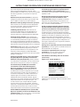
Page 1 – Language and Units Selection
Figure 17 : Language and Units Selection
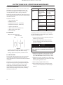
Language is selectable from the following 30 choices:
English (default)• Korean•
Bulgarian• Latvian•
Chinese, simplied• Lithuanian•
Croatian• Maltese•
Czech• Norwegian•
Danish• Polish•
Dutch• Portuguese•
Estonian• Romanian•
Finish• Russian•
French• Slovak•
German• Slovenian•
Greek• Spanish•
Hungarian• Swedish•
Italian• Thai•
Indonesian• Turkish•
The controller will display all screens in the selected
language and only one language can be selected at a
time.
Each language appears in its native translation.
Temperature is selectable between
o
F and
o
C.
Pressure is selectable between psi, kpa, bar, kg/cm
2
.
Page 2 – Time & Date Settings
Figure18 : Time & Date Settings
All items are adjustable.
Time allows the current time to be set in a 24 hour format
Date allows the current month, day, and year to be set
Date Format is selectable between dd/mm/yyyy
(default), mm/dd/yyyy, and YYYY/MM/DD
Conrm New Time and Date is used to verify that
changes to selections are desired. An “x” must appear in
the checkbox before any changes will take aect.
The controller will continue to display any changes, even
when the selections have not been conrmed and the
user exits the page, then returns. Cycling of the power
returns all selections to their current settings.
NOTICE
The controller does not support Daylight Savings
Time.
Page 3 – Backlight Settings
Figure 19 : Backlight Settings
Backlight Brightness adjusts the brightness of the display.
NOTICE
The backlight will be switched ON whenever any of
the controller’s keys are pressed.
WARNING
The start, stop, load, unload, reset, and
acknowledge keys on the controller remain
functional while the backlight is switched OFF. It is
recommended to press the enter key or one of the
navigation keys in order to switch the backlight ON.
Page 4 - Serial Port Address Settings
Figure 20 : Serial Port Address Settings
This page allows the user to set up the network addresses
for the RS-485 networks the controller is capable of
communicating with.
OPERATING INSTRUCTIONS XE70M CONTROLLER
RELEASED 20/Jul/2016 17:56:55 GMT

80448418 Rev.C 19
Active Protocol – Allows the serial port to be congured
to Airbus (used for X-Series system controllers and
integral sequencing) or Modbus protocols.
MODBUS Address – Sets the modbus node ID for the
controller to communicate with a Modbus capable
device, this can be any value between 1 and 254.
RS-485 Address – Sets the airbus address that allows the
controller to communicate over Integral Sequencing or
an X-Series system controller network.
Pages 5 & 6 – Ethernet Settings (ECO Module Only)
Please note that these pages will have no eect unless
the ECO module option has been purchased.
Figure 21 : Ethernet Settings (ECO Module Only)
IP Address Setting – When DHCP is not enabled, this
setpoint sets the IP address of the controller.
IP Address Actual – This will match the IP address setting
when DHCP is not enabled. If DHCP is enabled this will
display the address assigned to the controller by the
DHCP server.
Default Gateway Setting – Setpoint for the default
gateway.
Default Gateway Actual – Current reading/setting for
the default gateway.
Subnet Mask Setting – Setpoint for the subnet mask
Subnet Mask Actual – Current reading/setting for the
subnet mask
MAC Address – This is the unique hardware MAC address
for the controller. This can not be changed.
Enable DHCP – Allow the controller to automatically
receive an IP address from the Local Area Network (LAN)
Apply– After editing the desired setpoint navigate to the
accept setting and press enter in order for the values in
the setting variables to be conrmed by the controller.
Cancel – Discard any changes made to the Ethernet
settings.
INTEGRAL SEQUENCING FOLDER
Figure 22 : Integral Sequencing folder
Integral Sequencing allows the compressor to be
networked with up to three other compressors (xed or
variable speed) to maintain a stable system pressure by
loading and unloading compressors as needed. Integral
sequencing requires no additional hardware other than
a serial two wire connection daisy chained between all
compressors in the system, connected to port X04 on the
controller.
For a compressor to be a member of the integral
sequencing system, the COM control setpoint in
the operator settings tab must be enabled and the
compressor must be started via the local start button.
Additionally, it is recommended that the Auto-Restart
function be enabled as the integral sequencing system
OPERATING INSTRUCTIONS XE70M CONTROLLER
RELEASED 20/Jul/2016 17:56:55 GMT

20 80448418 Rev.C
will never start and stop machines, only load and unload
them. Integral sequencing relies on Auto-Restart to turn
OFF the compressor motor when not needed.
Please note that the compressor’s address in the integral
sequencing system is dened by the RS-485 address that
is set on the general settings folder. Also note that the
pressure signal used to determine when to load or unload
another compressor is based on the pressure reading
from the compressor assigned as the integral sequencing
master. Lastly, note that the Active Protocol on the
general settings tab must be set to Airbus485 for integral
sequencing to operate properly.
Certain functions may interfere with compressors loading
and unloading:
Verify that the Remote Load Enable switch is in the
open position. Having this closed will allow the remote
load/unload switch to dene the load command.
Start Delay Interval – Determines the amount of
time between loading compressors. This prevents all
compressors from loading at once. This setpoint should
be set to the longest starting time of any compressor in
the system. In general, this will be equivalent to the star/
delta transition time for a xed speed machine, or ramp
time for a VSD machine.
Damping – The pressure control “Damping” setting
which is used to tune how quickly the system responds
to pressure deviations. The default is 10 and should not
normally be changed.
Tolerance - The pressure control “Tolerance” setting,
which is used to tell the system how to respond to
changes in pressure above and below the load/unload
pressures. The default is 3.0 psi and should not normally
be changed.
Number of Compressors – Denes how many
compressors are in the system. There is a maximum of 4.
Priority – Each compressor can be assigned a priority
level. Setting a priority for a compressor aects how
the rotation will occur. Compressors with priority 1 will
always be in the lead position(s), followed by priority 2
compressors, and so on. Compressors will only rotate
positions with other compressors of the same priority
level.
•
Sequence – Displays the current load/unload order of
the system. Each compressor in the system is assigned
a letter. The letter indicates whether the machine with
the assigned Airbus address is a lead machine (loads
rst, unloads last) or one of the trim machines. Letter A
is assigned to the lead machine, B to the next machine
to load, C to the third machine to load, and D to the nal
machine to load. Machines will unload in the reverse
order, such that A will be the last machine running.
The rst position in the - - - - sequence on Integral
Sequencing tab, page 3 always refers to the compressor
that is assigned Airbus Address 1. The second position to
Airbus Address 2, and so on. Note that the letter sequence
may change due to rotation.
Note that the sequence will only be displayed on the
master controller.
Rotate Now – Selecting this setpoint will cause the
sequence to shift according to the priorities, regardless of
the rotation interval setpoint.
Rotation Interval – Determines the time period between
automatic sequence rotations.
Time Left – Counts down the time until the sequence
rotation will occur.
System Pressure – Shows the current pressure reading
that the system is using for control. This will only be
shown on the sequence Master controller.
STATUS FOLDER
NOTICE
All information on these pages is read only.
NOTICE
Some values may only be visible when the factory
settings password is entered.
Page 1 – Analog Inputs
Figure 23 : Analog Inputs
Analog Inputs:
The following analog inputs are displayed in this section.
Package Discharge Pressure – The pressure the
compressor is delivering to the plant
Sump Pressure – The compressor’s internal pressure
at the sump tank.
•
•
OPERATING INSTRUCTIONS XE70M CONTROLLER
RELEASED 20/Jul/2016 17:56:55 GMT
A página está carregando...
A página está carregando...
A página está carregando...
A página está carregando...
A página está carregando...
A página está carregando...
A página está carregando...
A página está carregando...
A página está carregando...
A página está carregando...
A página está carregando...
A página está carregando...
A página está carregando...
A página está carregando...
A página está carregando...
A página está carregando...
A página está carregando...
A página está carregando...
A página está carregando...
A página está carregando...
A página está carregando...
A página está carregando...
A página está carregando...
A página está carregando...
A página está carregando...
A página está carregando...
A página está carregando...
A página está carregando...
A página está carregando...
A página está carregando...
A página está carregando...
A página está carregando...
A página está carregando...
A página está carregando...
A página está carregando...
A página está carregando...
A página está carregando...
A página está carregando...
A página está carregando...
A página está carregando...
A página está carregando...
A página está carregando...
A página está carregando...
A página está carregando...
A página está carregando...
A página está carregando...
A página está carregando...
A página está carregando...
A página está carregando...
A página está carregando...
A página está carregando...
A página está carregando...
A página está carregando...
A página está carregando...
A página está carregando...
A página está carregando...
A página está carregando...
A página está carregando...
A página está carregando...
A página está carregando...
A página está carregando...
A página está carregando...
A página está carregando...
A página está carregando...
A página está carregando...
A página está carregando...
A página está carregando...
A página está carregando...
A página está carregando...
A página está carregando...
A página está carregando...
A página está carregando...
A página está carregando...
A página está carregando...
A página está carregando...
A página está carregando...
A página está carregando...
A página está carregando...
A página está carregando...
A página está carregando...
A página está carregando...
A página está carregando...
A página está carregando...
A página está carregando...
A página está carregando...
A página está carregando...
A página está carregando...
A página está carregando...
A página está carregando...
A página está carregando...
A página está carregando...
A página está carregando...
A página está carregando...
A página está carregando...
A página está carregando...
A página está carregando...
A página está carregando...
A página está carregando...
A página está carregando...
A página está carregando...
A página está carregando...
A página está carregando...
A página está carregando...
A página está carregando...
A página está carregando...
A página está carregando...
A página está carregando...
A página está carregando...
A página está carregando...
A página está carregando...
A página está carregando...
A página está carregando...
A página está carregando...
A página está carregando...
A página está carregando...
A página está carregando...
A página está carregando...
A página está carregando...
A página está carregando...
A página está carregando...
A página está carregando...
A página está carregando...
A página está carregando...
A página está carregando...
A página está carregando...
A página está carregando...
A página está carregando...
A página está carregando...
A página está carregando...
A página está carregando...
A página está carregando...
A página está carregando...
A página está carregando...
A página está carregando...
A página está carregando...
A página está carregando...
-
 1
1
-
 2
2
-
 3
3
-
 4
4
-
 5
5
-
 6
6
-
 7
7
-
 8
8
-
 9
9
-
 10
10
-
 11
11
-
 12
12
-
 13
13
-
 14
14
-
 15
15
-
 16
16
-
 17
17
-
 18
18
-
 19
19
-
 20
20
-
 21
21
-
 22
22
-
 23
23
-
 24
24
-
 25
25
-
 26
26
-
 27
27
-
 28
28
-
 29
29
-
 30
30
-
 31
31
-
 32
32
-
 33
33
-
 34
34
-
 35
35
-
 36
36
-
 37
37
-
 38
38
-
 39
39
-
 40
40
-
 41
41
-
 42
42
-
 43
43
-
 44
44
-
 45
45
-
 46
46
-
 47
47
-
 48
48
-
 49
49
-
 50
50
-
 51
51
-
 52
52
-
 53
53
-
 54
54
-
 55
55
-
 56
56
-
 57
57
-
 58
58
-
 59
59
-
 60
60
-
 61
61
-
 62
62
-
 63
63
-
 64
64
-
 65
65
-
 66
66
-
 67
67
-
 68
68
-
 69
69
-
 70
70
-
 71
71
-
 72
72
-
 73
73
-
 74
74
-
 75
75
-
 76
76
-
 77
77
-
 78
78
-
 79
79
-
 80
80
-
 81
81
-
 82
82
-
 83
83
-
 84
84
-
 85
85
-
 86
86
-
 87
87
-
 88
88
-
 89
89
-
 90
90
-
 91
91
-
 92
92
-
 93
93
-
 94
94
-
 95
95
-
 96
96
-
 97
97
-
 98
98
-
 99
99
-
 100
100
-
 101
101
-
 102
102
-
 103
103
-
 104
104
-
 105
105
-
 106
106
-
 107
107
-
 108
108
-
 109
109
-
 110
110
-
 111
111
-
 112
112
-
 113
113
-
 114
114
-
 115
115
-
 116
116
-
 117
117
-
 118
118
-
 119
119
-
 120
120
-
 121
121
-
 122
122
-
 123
123
-
 124
124
-
 125
125
-
 126
126
-
 127
127
-
 128
128
-
 129
129
-
 130
130
-
 131
131
-
 132
132
-
 133
133
-
 134
134
-
 135
135
-
 136
136
-
 137
137
-
 138
138
-
 139
139
-
 140
140
-
 141
141
-
 142
142
-
 143
143
-
 144
144
-
 145
145
-
 146
146
-
 147
147
-
 148
148
-
 149
149
-
 150
150
-
 151
151
-
 152
152
-
 153
153
-
 154
154
-
 155
155
-
 156
156


Ingersoll-Rand UP6S 20 Installation, Operation and Maintenance Manual
- Tipo
- Installation, Operation and Maintenance Manual
em outras línguas
- español: Ingersoll-Rand UP6S 20
- français: Ingersoll-Rand UP6S 20
- English: Ingersoll-Rand UP6S 20
Artigos relacionados
-
Ingersoll-Rand R30 Product Maintenance Information
-
-
-
-
-
-
-
-
-
Ingersoll-Rand Sierra Series Operation and Maintenance Manual
Outros documentos
-
Panasonic CZ02RT11P Instruções de operação
-
Sunstech Fauno CL Guia rápido
-
 dirna Bergstrom SlimFIT RENAULT NET Manual do usuário
-
Full Gauge Controls TO-712B Manual do proprietário
-
Thrustmaster TCA QUADRANT ADD-ON KONTROLLER Manual do usuário
-
 Seeley TBS Manual do proprietário
-
sauter TKP 80, 81 Assembly Instructions
-
dirna Bergstrom SlimFit Manual do usuário
-
Honeywell SV2 Series Instruções de operação
-
Samoa 365657 Instructions Manual

