Ingersoll-Rand ENL 10 Instructions For Installation And Operation Manual
- Tipo
- Instructions For Installation And Operation Manual

Save These Instructions
Instructions for Installation
and Operation
Instruções de instalação e de serviço
PT
Instructions de montage et de service
FR
Instruciones de instalación y de servicio
ES
Instructions for Installation and Operation
EN
80446222
Revision B
October 2014
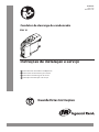
Condensate Drain
ENL 10
PRINT LANGUAGE
ENGLISH
FRENCH
PORTUGUESE
SPANISH
01-2690

EN
2 ingersollrandproducts.com 80446222
CONTENTS
CONTENTS PAGE
1. PICTOGRAMS AND SYMBOLS 3
2. SAFETY INSTRUCTIONS 3
3. PROPER USE 4
4. EXCLUSION FROM THE SCOPE OF
APPLICATION 4
5. TECHNICAL DATA 5
6. ELECTRICAL DATA 6
7. DIMENSION DRAWING 7
CONTENTS PAGE
8. FUNCTION 8
9. INSTALLATION 10
10. ELECTRICAL INSTALLATION 12
11. CONTROL AND MAINTENANCE 15
12. TROUBLESHOOTING AND FAULT
ELIMINATION 19
13. ELEMENTS AND COMPONENTS 20
14. RECOMMENDED SPARE PARTS 21

80446222 ingersollrandproducts.com 3
EN
1. PICTOGRAMS AND SYMBOLS
Observe the installation and operating instructions
Observe the installation and operating instructions
(on the type plate)
General danger symbol (danger, warning, caution)
General danger symbol (danger, warning, caution) for supply voltage and supply voltage carrying
plants components
2. SAFETY INSTRUCTIONS
Please check whether or not these
instructions correspond to the device
type.
Adhere to all advice given in these
operating instructions. They include
essential information which must
be observed during the installation,
operation and maintenance. Therefore it is
imperative for the service technician and
the responsible operator / technical sta
to read these operating instructions prior
to installation, start-up and maintenance.
The operating instructions must be
accessible at any time at the place of
application of the ENL 10.
In addition to these operating instructions,
local or national regulations must be
complied with, if necessary.
Make sure that the ENL 10 is operated
only within the permissible limit values
indicated on the ID plate. Any deviation
involves a risk for persons and materials,
and may result in malfunction and service
failures.
If you have any queries regarding these
installation- and operating instructions,
please contact Ingersoll Rand.
DANGER
Compressed air!
Risk of serious injury or death through contact
with quickly or suddenly escaping compressed air
or through bursting plant components or plant
components which are not secured.
Measures:
Do not exceed the maximum operating pressure (see
type plate).
Only carry out service measures when the system is
pressure less.
Use pressure-resistant installation material only.
The feed pipe must be tubed rmly. Discharge pipe:
short, xed pressure hose onto pressure-resistant pipe.
Make sure that persons or objects cannot be hit by
condensate or escaping compressed air.
DANGER
Supply voltage!
There is the risk of an electric shock involving injury or
death when coming into contact with
non- insulated components carrying supply voltage.
Measures:
During electric installations, all regulations in force
need to be adhered to (e.g. VDE 0100 / IEC 60364).
Service measures must only be undertaken when
the system is deactivated.
The removed control unit has no IP degree of
protection.
All types of electrical works must be carried out by
authorized and qualied personnel only.
•
•
•
•
•
•
•
•
•

4 ingersollrandproducts.com 80446222
EN
Further safety instructions:
For installation and operation, the national regulations
and safety codes in force must also be adhered to.
Do not use the ENL 10 in hazardous areas.
Regarding the inlet screw joints, excessive tightening
forces must be avoided. This applies in particular to
conical screw joints.
The ENL 10 will only function when voltage is applied.
Do not use the test button for permanent drainage.
Use genuine spare parts only. This is imperative to
ensure perfect functioning.
Additional advice:
During installation, use spanner at at the feed pipe
(wrench size SW27) as a back rest.
The service unit must not be dismantled.
•
•
•
•
•
•
•
•
CAUTION
Malfunction during operation!
Through incorrect installation and poor maintenance,
malfunction may occur at the ENL 10.
Condensate which is not discharged may cause damage
to plants and in production processes.
Measures:
Condensate drainage which is reliable in performance
directly optimizes the compressed-air quality.
To prevent damage and breakdowns, it is imperative
to observe the following:
Exact compliance with the specications of use
and with the performance parameters of the
ENL 10, in connection with the case of application
(see “Proper use” section)
Exact compliance with the installation- and
operation instructions in this manual
Regular maintenance and control of the ENL 10 in
accordance with the instructions in this operating
manual.
•
•
a.
b.
c.
3. PROPER USE
The ENL 10 is an electronically level-controlled
condensate drain for compressed-air plants.
The device is employed within the permissible
performance parameters (see “Technical data”).
The ENL 10 is able to drain condensate under
operating pressure from the plant components
virtually without compressed-air loss.
For its function, the ENL 10 requires an supply voltage
and an operating pressure (see “Technical data”).
As far as the employment in plants with increased
demands on compressed air is concerned (food
•
•
•
•
•
industry, medical technology, laboratory equipment,
special processes etc.), the operator must decide on
measures for the monitoring of the compressed-air
quality. These have an eect on the safety of the
subsequent processes and may prevent damage to
persons and plants.
It is the task of the operator to ensure that the
indicated conditions are met during the entire
operating time.
For the employment in CO2 plants, a ENL 10 with a CO
specication must be used.
•
•
4. EXCLUSION FROM THE SCOPE OF APPLICATION
The ENL 10 as a condensate drain alone cannot
guarantee a dened compressed-air quality, for
this purpose, other additional technical devices are
required.
ENL 10 is not suitable for use in plants carrying
vacuum or atmospheric ambient pressure or in ex-
areas.
ENL 10 must not be exposed to permanent direct solar
•
•
•
or thermal radiation.
ENL 10 must not be installed and operated in areas
with an aggressive atmosphere.
The ENL 10 is not heatable and, therefore, not suitable
for the use in areas where frost is likely to occur.
•
•
2. SAFETY INSTRUCTIONS

80446222 ingersollrandproducts.com 5
EN
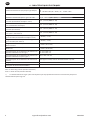
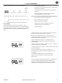
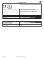
min./max. operating pressure
(see type plate)
0,8...16 bar (12...230 psi) or 1,2...16 bar (17...230 psi)
min./max. temperature
(see type plate)
+1...+60 °C (+34...+140 °F) or +1...+70 °C (+34...+158 °F)
Condensate inow 3 x NPT ½ (½”) internal
Condensate outow G ½ (½”) Ø 13 mm hose connector
Condensate oil-contaminated + oil-free
Housing aluminium + plastic, glass bre-reinforced
Weight (empty) 1,65 kg (3.63 lbs)
This product has been tested to the requirements of CAN/CSA-C22.2 No. 61010-1-12, third edition, including a later version of
the same standard incorporation the same level of testing requirements.
Peak compressor performance 500 scfm
Peak refrig. dryer performance
(only with pre-separation)
1,000 scfm
Peak lter performance
(behind dryer)
5,000 scfm
5. TECHNICAL DATA

6 ingersollrandproducts.com 80446222
EN
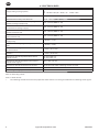
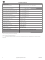
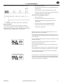
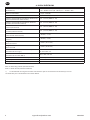
6. ELECTRICAL DATA
Supply voltage (see type plate)
95…240 VAC ±10% (50…60 Hz) /100…125 VDC ±10%
or
24…48 VAC ±10% (50…60 Hz) / 18…72 VDC ±10%
Power consumption P = 0,6 ... 3 VA (W)
Recommended cable-jacket diameter Ø 5,0…10 mm (0,20“…0,39“)
Recommended wire cross section Spring-loaded
terminal (voltage supply/relay)
0,75...1,5 mm² (AWG 16...20)
Recommended wire cross section
Screw terminal (voltage supply)
0,75...2,5 mm² (AWG 14...20)
Recommended wire cross section Spring-loaded
terminal (external test)
0,75...1,0 mm² (AWG 18...20)
Recommended wire cross section Screw terminal
(relay/external test)
0,75...1,5 mm² (AWG 16...20)
Recommended stripping of cable jacket (voltage
supply/relay)
~ 30 mm (~ 1.18”)
Recommended stripping of cable jacket (external
test)
~ 90 mm (~ 3.54”)
Recommended length of the wire end tube Spring-
loaded terminal
~ 8 mm (~ 0.31 inch)
Recommended length of the wire end tube Screw
terminal
~ 6 mm (~ 0.24 inch)
Connection data of the potentialfree contact
Switch to load*
AC: max. 250V / 1A
DC: max. 30V / 1A
Connection data of the potential-free contact
Switch to low signal*)
min. 5 VDC / 10 mA
Connection data of the external test contact on the unit side 5 VDC; switching current ≥ 0,5 mA
Protection class IP 67
Overvoltage category (IEC 61010-1) II
VAC = V alternating current
VDC = V direct current
* The switching of loads means that the properties of the contact are no longer suitable for the switching of low signals.

80446222 ingersollrandproducts.com 7
EN
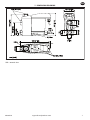
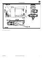
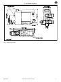
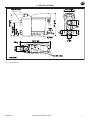
7. DIMENSION DRAWING
SW = wrench size

8 ingersollrandproducts.com 80446222
EN
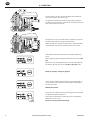
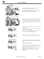
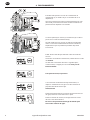
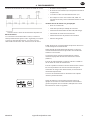
8. FUNCTION
Via the inlet line (1) the condensate ows into the ENL 10
and accumulates in the housing (2).
A capacitive functioning sensor (3) continuously registers
the lling level and relays a signal to the electronic control as
soon as the container is lled.
The pilot valve (4) is activated and the membrane (5) opens
the outlet line to discharge the condensate (6).
When the ENL 10 is empty, the outlet line is reclosed tightly
in time before unnecessary compressedair losses occur.
At the ENL 10, two LEDs indicate the individual operating
states.
When applying supply voltage, the ENL 10 carries out a self-
test.
Both LEDs are lit for approximately 1 second, subsequently,
the device changes over to the “ready-to-operate” state.
Ready to operate, voltage is applied.
In the event that the condensate discharge is disturbed, an
alarm mode will start which is indicated by the ashing of
the red alarm LED.
Malfunction/alarm
Test of the valve function (manual drainage): press and hold
the button for approximately 2 s.
Test of the alarm function (see below): press and hold the
button for at least 1 min.
Do not use for permanent drainage.

80446222 ingersollrandproducts.com 9
EN
Switching sequence of the valve in the alarm mode.
Trouble indication via a potential-free contact
Alarm mode:
In the event that the condensate discharge is disturbed, the
valve opens after a time cycle (approx. every three seconds)
to eliminate the malfunction automatically. If the malfunction
is not eliminated after one minute, a trouble indication is
released:
The alarm LED ashes
The alarm relay switches over (the signal can be picked
o potential-freely).
The valve opens every four minutes for 7.5 seconds.
When the malfunction has been eliminated, the ENL
10 will switch back automatically into the normal
mode.
Possible trouble sources include:
Mistakes during installation
Dropping below the minimum pressure
Excessive accumulation of condensate (excess load)
Blocked / obstructed outlet line
Extreme amount of dirt particles
Frozen pipe work
•
•
•
•
•
•
•
•
•
•
8. FUNCTION
The ENL 10 releases a maintenance message for a service
that is to be carried out.
Depending on the operating mode, a visual maintenance
message (service) is activated which signalizes the
replacement of the service unit.
The maintenance message is indicated by the ashing
supply voltage-LED “Power”.
The maintenance message is released after 2 x 8,760 h or
one million switching cycles.
The maintenance signal is released when one of these two
values is reached.
In the event of a power outage or when the energy supply is
deactivated, the status of the timer will be maintained.
The activities to be carried out regarding maintenance are
described in the chapter entitled “Check and maintenance”.
Prior to the replacement of the service unit, a reset needs to
be carried out. The control unit is released by actuating the
arresting hook. When removed, the TEST button must be
pressed and held for at least ve seconds.

10 ingersollrandproducts.com
380446222
EN
DANGER
Compressed air!
Risk of serious injury or death through contact
with quickly or suddenly escaping compressed air
or through bursting plant components or plant
components which are not secured.
Measures:
Do not exceed the maximum operating pressure (see
type plate).
Only carry out service measures when the system is
pressure less.
Use pressure-resistant installation material only.
The feed pipe must be tubed rmly. Discharge pipe:
short, xed pressure hose onto pressure-resistant pipe.
Make sure that persons or objects cannot be hit by
condensate or escaping compressed air.
CAUTION
Malfunction during operation!
Through incorrect installation and poor maintenance,
malfunction may occur at the ENL 10.
Condensate which is not discharged may cause
damage to plants and in production processes.
Measures:
Condensate drainage which is reliable in performance
directly optimizes the compressed-air quality.
To prevent damage and breakdowns, it is imperative
to observe the following:
Exact compliance with the specications of use
and with the performance parameters of the
ENL 10, in connection with the case of application
(see “Proper use” section)
Exact compliance with the installation- and
operation instructions in this manual
Regular maintenance and control of the ENL 10 in
accordance with the instructions in this operating
manual.
•
•
•
•
•
•
•
a.
b.
c.
NOTE
It is imperative to observe all hazard statements and
warnings listed here.
Please also observe all regulations and notes regarding
industrial safety and re prevention at the place of
installation.
As a matter of principle, only use suitable and appropriate
tools and materials in a proper condition.
Do not use aggressive cleaners and improper devices such
as high-pressure cleaners.
Please note that condensates may contain aggressive or
harmful components. Therefore, skin contact should be
avoided.
Condensate is subject to mandatory waste disposal. As
such, it must be collected in suitable containers, and
disposed of or processed properly.
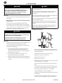
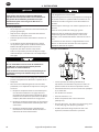
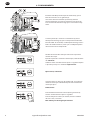
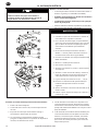
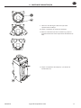
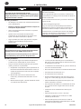
Installation instructions:
Only the displayed installation position of the ENL 10
(3) is permissible. Never install in a horizontal or any
other tilted position.
Feed pipe (1) and ball valve (2) at least G½.
No lter or screen in the inlet line.
Slope in the inlet line >1%.
Use ball valves (2) only.
Operating pressure: min. 0,8/1,2 bar (12/17 psig), max.
16 bar (230 psig). See type plate.
Short pressure hose (4) xed on a pressureresistant
pipe.
The required minimum pressure increases by 0,1 bar
(1,4 psi) per metre gradient in the discharge pipe (5).
Discharge pipe (5) rising by max. 5 m (16,4ft).
Install manifold (6) ¾” with a slope of 1%.
Introduce the discharge pipe (5) from the top into the
manifold (6).
Prior to the start-up, always carry out a leak test and
verify the correct engagement of the control unit.
•
•
•
•
•
•
•
•
•
•
•
•
9. INSTALLATION

80446222 ingersollrandproducts.com 11
EN
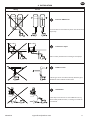
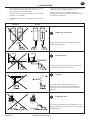
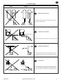
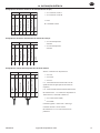
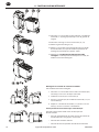
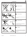
Wrong Correct
Pressure dierences!
Each condensate accumulation point must be drained
separately.
Continuous slope!
Avoid a water pocket when installing the feed pipe
Deector area!
If drainage is to be carried out directly from the pipe,
deection of the air ow will be useful.
Ventilation!
If the slope in the inlet line is not sucient or if any
other inow problems occur, a venting line needs to
be installed.
9. INSTALLATION

12 ingersollrandproducts.com 80446222
EN
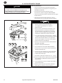
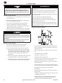
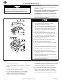
10. ELECTRICAL INSTALLATION
DANGER
Supply voltage!
There is the risk of an electric shock involving injury or
death when coming into contact with non-insulated
components carrying supply voltage.
Measures:
During electric installations, all regulations in force
need to be adhered to (e.g. VDE 0100 / IEC 60364).
Service measures must only be undertaken when
the system is deactivated.
The removed control unit has no IP degree of
protection.
All types of electrical works must be carried out by
authorized and qualied personnel only.
•
•
•
•
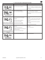
NOTE
Power supply connection:
Read the permissible supply voltage on the type
plate and make sure this voltage is observed.
For the supply voltage, a reliably accessible
separator must be provided close-by (e.g. power
plug or switch), which separates all current-
carrying conductors.
At a low voltage supply (< 50 VAC / < 75
VDC), only
use a protective extra- low-voltage (SELV).
Carry out installation in accordance with VDE 0100
/ IEC 60364.
Observe the terminal assignment.
D
o not install when the device is energized.
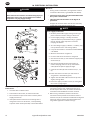
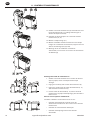
Unscrew the screws (1) and remove the upper part
of the cover (2).
Unscrew the threaded cable connection (3),
remove the plug (if ther
e is one), and lead the
cable (4) for the power supply through.
Connect the cable (4) with terminals X1 (1.1, 1.2)
(5).
Install the cables as shown (see also terminal
assignment in the follo
wing text).
Tighten the threaded cable connection (3) with a
slightly sealing e
ect.
Put on the upper part of the cover (2) and tighten
the screws (1) ngertight.
1.
2.
3.
4.
5.
6.
7.
8.
9.
10.
11.
12.
Connection of the potential-free contact and of the
external test:
Selection of the suitable cable.
Connection to X2 and X3, as shown on the left.
The installation steps are the same as for the power
supply connection.
If the potential-free contact carries voltage that is
dangerous in the case of contact, a corresponding
separator must also be provided, as described above.
1.
2.
3.
4.
When using the potential-free contacts and the
connection external test, sucient clearance to
the other parts of the unit, or suitable insulation in
accordance with EN 60664-1 must be ensured.
When using a multiwire, common line for the
connection of the potential-free contact and the
external test, this line must be suitable for the highest
occurring voltage and the intended temperature
range with regard to its nominal ratings.
5.
6.

80446222 ingersollrandproducts.com 13
EN
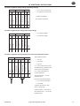
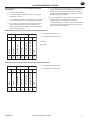
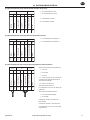
Terminal assignment supply voltage (operating voltage)
X 1
X 2 X 3
1
2 1 2 3
1 2
phase
neutral
normally open
common
normally closed
external test (IN1)
GND
1.1
1.2
2.1
2.2
2.3
3.1
3.2
X 1.1 L mains connection
X 1.2 N mains connection
L = Outer conductor
N = Neutral conductor
•
•
Terminal assignment low voltage (operating voltage)
X 1
X 2 X 3
1
2 1 2 3
1 2
phase
neutral
normally open
common
normally closed
external test (IN1)
GND
1.1
1.2
2.1
2.2
2.3
3.1
3.2
X 1.1 Power supply
X 1.2 Power supply
•
•
Terminal assignment of the potential-free contact and of the external test
X 1
X 2 X 3
1
2 1 2 3
1 2
power
power
normally open
common
normally closed
external t est (IN1)
GND
1.1
1.2
2.1
2.2
2.3
3.1
3.2
Alarm/potential-free:
X 2.1 n.o.
X 2.2 com.
X 2.3 n.c.
n.c. - com. Closed in the event
of malfunction or power failure
(closed-current principle).
n.o. - com. Closed during
normal operation.
The contacts X2.1 - 2.3 are
potential-free.
External test/remote control:
X 3.1 externer Test (IN1)
X 3.2 GND
Contacts connected = test
active = discharge
Contacts open = test inactive
The contacts X 3.1 -3.2 are not
potential-free.
•
•
•
•
•
10. ELECTRICAL INSTALLATION

14 ingersollrandproducts.com 80446222
EN
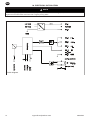
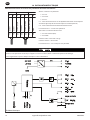
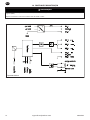
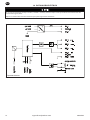
NOTE
At a low voltage supply (< 50 VAC / < 75 VDC), only use a protective extra-low-voltage (PELV).
Tighten the threaded cable connection with a slightly sealing eect.
Electric diagram
10. ELECTRICAL INSTALLATION

80446222 ingersollrandproducts.com 15
EN
DANGER
Compressed air!
Risk of serious injury or death through contact
with quickly or suddenly escaping compressed air
or through bursting plant components or plant
components which are not secured.
Measures:
Do not exceed the maximum operating pressure (see
type plate).
Only carry out service measures when the system is
pressure less.
Use pressure-resistant installation material only.
The feed pipe must be tubed rmly. Discharge pipe:
short, xed pressure hose onto pressure-resistant pipe.
Make sure that persons or objects cannot be hit by
condensate or escaping compressed air.
DANGER
Supply voltage!
There is the risk of an electric shock involving injury or
death when coming into contact with non-insulated
components carrying supply voltage.
Measures:
During electric installations, all regulations in force
need to be adhered to (e.g. VDE 0100 / IEC 60364).
Service measures must only be undertaken when
the system is deactivated.
The removed control unit has no IP degree of
protection.
All types of electrical works must be carried out by
authorized and qualied personnel only.
•
•
•
•
•
•
•
•
•
CAUTION
Malfunction during operation!
Through incorrect installation and poor maintenance,
malfunction may occur at the ENL 10.
Condensate which is not discharged may cause damage
to plants and in production processes.
Measures:
Condensate drainage which is reliable in performance
directly optimizes the compressed-air quality.
To prevent damage and breakdowns, it is imperative
to observe the following:
Exact compliance with the specications of use
and with the performance parameters of the ENL
10, in connection with the case of application (see
“Proper use” section)
Exact compliance with the installation- and
operation instructions in this manual
Regular maintenance and control of the ENL 10 in
accordance with the instructions in this operating
manual.
NOTE
It is imperative to observe all hazard statements and
warnings listed here.
Please also observe all regulations and notes regarding
industrial safety and re prevention at the place of
installation.
As a matter of principle, only use suitable and appropriate
tools and materials in a proper condition.
Do not use aggressive cleaners and improper devices such
as high-pressure cleaners.
Please note that condensates may contain aggressive or
harmful components. Therefore, skin contact should be
avoided.
Condensate is subject to mandatory waste disposal. As
such, it must be collected in suitable containers, and
disposed of or processed properly.
•
•
a.
b.
c.
11. CONTROL AND MAINTENANCE

16 ingersollrandproducts.com 80446222
EN
Maintenance recommendation:
After 2 x 8,760 operating hours or one million switching
cycles, a maintenance message is released.
The green power LED ashes. Afterwards, or at the latest
after two years (2 x 8,760 operating hours), the service unit
(5) needs to be replaced.
Prior to the replacement of the service unit, a reset
needs to be carried out. The control unit is released
by actuating the arresting hook. When removed, the
TEST button below the LED must be pressed and held
for at least ve seconds.
1.
It is recommended to clean the condensate receiver tank
after two years at the latest, when maintenance works are
carried out:
2. Remove the control unit (1) by pressing the arresting
hook (23).
3. Unfasten the ENL 10 from the outlet.
4. Detach from the tubing at the inlet.
5. Unscrew both M6 erection bolts (22) and remove the
service unit (9) by slightly pulling and lifting it.
6. Remove the design shell (11) using a screwdriver.
7. Unscrew the four cover screws (16) and remove the
cover (17).
8. Clean the condensate receiver tank (19).
11. CONTROL AND MAINTENANCE

80446222 ingersollrandproducts.com 17
EN
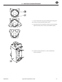
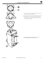
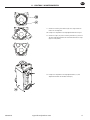
9. Insert new cover O-ring (18) according to the diagram.
10. Clean the sealing surfaces of the cover.
11. Put on the cover (17) with the new O-ring and carefully
tighten the four cover screws (16) crosswise (8 Nm).
12. Clean the sealing surfaces () at the condensate
receiver tank (19).
11. CONTROL AND MAINTENANCE

18 ingersollrandproducts.com 80446222
EN
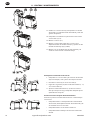
13. Check whether or not the service unit (9) goes with the
control unit (1...8) (model designation and color of the
arresting hook).
14. Check the O-rings at the new service unit (12, 13).
15. Mount the design shell (11).
16. Mount the service unit along with the design shell at
the condensate receiver tank (19) and tighten both
erection bolts (22) (2,5 Nm).
17. Re-install the ENL 10 at the inlet tubing and outlet, in
reverse order to disassembly.
Installation of the control unit on the ENL 10:
Check whether or not the service unit with contact
springs (28) is clean, dry, and free from impurities.
Introduce the sensor (5) into the service unit (9).
Hang the hook (29) of the control unit (1...8) in the
service unit (9).
Press the control unit (1...8) against the service unit (9),
snap into place and make sure it is securely mounted.
1.
2.
3.
4.
Start-up subsequent to maintenance measures:
Always carry out prior to the start-up:
Leak test of the screwed connector of the condensate
receiver tank and of the connection of this tank to the
service unit.
Check of the electrical connections.
Check of the correct engagement of the control unit.
•
•
•
11. CONTROL AND MAINTENANCE

80446222 ingersollrandproducts.com 19
EN
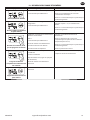
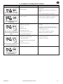
12. TROUBLESHOOTING AND FAULT ELIMINATION
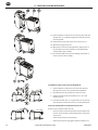
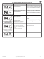
Symptoms Possible reasons Measures
No LED lights up
Supply voltage incorrect.
Circuit board defective.
Check the voltage on the type plate.
Check the connections and the supply voltage.
Check the circuit boards for possible damage.
All LEDs are continuously on
Failure during the start of the program.
Circuit board defective.
Separate the device from the supply voltage
and reactivate after > 5 s.
Check the circuit boards for possible damage.
Test button pressed, but no
condensate discharge
Feed pipe and/or discharge pipe
blocked or obstructed.
Wear and tear.
Circuit board defective.
Service unit defective.
Minimum pressure not reached.
Maximum pressure exceeded.
Check feed and discharge pipe.
Check whether or not the valve opens audibly
(press the test button several times for >2
seconds).
Check the circuit board for possible damage.
Check the operating pressure.
Condensate discharge only
when the test button is
pressed
Feed pipe without sucient slope.
Cross section not large enough.
Condensate accumulation too high
(surge).
Service unit extremely dirty.
Install feed pipe with a slope.
Replace the service unit.
Device blows o continuously
Service unit defective or dirty. Replace the service unit.

20 ingersollrandproducts.com 80446222
EN
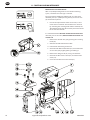
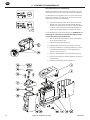
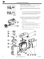
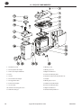
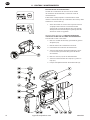
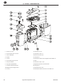
13. ELEMENTS AND COMPONENTS
Screw 3.5 x 10
Upper part of the cover
Molded gasket
Circuit board
Sensor
Lower part of the cover
Cable bushing
Sealing mat
Service unit
Hose connector G ½
Design shell
1.
2.
3.
4.
5.
6.
7.
8.
9.
10.
11.
O-ring 8 x 4
O-ring 18.5 x 2
Locking screw G ½
Flat gasket
Hexagon socket head screw M6 x 16
Lid
O-ring 48.9 x 2.62
Condensate receiver tank
Flat gasket
Locking screw G ½
Cross recessed head screw M6 x 16
12.
13.
14.
15.
16.
17.
18.
19.
20.
21.
22.
A página está carregando...
A página está carregando...
A página está carregando...
A página está carregando...
A página está carregando...
A página está carregando...
A página está carregando...
A página está carregando...
A página está carregando...
A página está carregando...
A página está carregando...
A página está carregando...
A página está carregando...
A página está carregando...
A página está carregando...
A página está carregando...
A página está carregando...
A página está carregando...
A página está carregando...
A página está carregando...
A página está carregando...
A página está carregando...
A página está carregando...
A página está carregando...
A página está carregando...
A página está carregando...
A página está carregando...
A página está carregando...
A página está carregando...
A página está carregando...
A página está carregando...
A página está carregando...
A página está carregando...
A página está carregando...
A página está carregando...
A página está carregando...
A página está carregando...
A página está carregando...
A página está carregando...
A página está carregando...
A página está carregando...
A página está carregando...
A página está carregando...
A página está carregando...
A página está carregando...
A página está carregando...
A página está carregando...
A página está carregando...
A página está carregando...
A página está carregando...
A página está carregando...
A página está carregando...
A página está carregando...
A página está carregando...
A página está carregando...
A página está carregando...
A página está carregando...
A página está carregando...
A página está carregando...
A página está carregando...
A página está carregando...
A página está carregando...
A página está carregando...
A página está carregando...
A página está carregando...
A página está carregando...
A página está carregando...
A página está carregando...
A página está carregando...
A página está carregando...
A página está carregando...
A página está carregando...
A página está carregando...
A página está carregando...
A página está carregando...
A página está carregando...
-
 1
1
-
 2
2
-
 3
3
-
 4
4
-
 5
5
-
 6
6
-
 7
7
-
 8
8
-
 9
9
-
 10
10
-
 11
11
-
 12
12
-
 13
13
-
 14
14
-
 15
15
-
 16
16
-
 17
17
-
 18
18
-
 19
19
-
 20
20
-
 21
21
-
 22
22
-
 23
23
-
 24
24
-
 25
25
-
 26
26
-
 27
27
-
 28
28
-
 29
29
-
 30
30
-
 31
31
-
 32
32
-
 33
33
-
 34
34
-
 35
35
-
 36
36
-
 37
37
-
 38
38
-
 39
39
-
 40
40
-
 41
41
-
 42
42
-
 43
43
-
 44
44
-
 45
45
-
 46
46
-
 47
47
-
 48
48
-
 49
49
-
 50
50
-
 51
51
-
 52
52
-
 53
53
-
 54
54
-
 55
55
-
 56
56
-
 57
57
-
 58
58
-
 59
59
-
 60
60
-
 61
61
-
 62
62
-
 63
63
-
 64
64
-
 65
65
-
 66
66
-
 67
67
-
 68
68
-
 69
69
-
 70
70
-
 71
71
-
 72
72
-
 73
73
-
 74
74
-
 75
75
-
 76
76
-
 77
77
-
 78
78
-
 79
79
-
 80
80
-
 81
81
-
 82
82
-
 83
83
-
 84
84
-
 85
85
-
 86
86
-
 87
87
-
 88
88
-
 89
89
-
 90
90
-
 91
91
-
 92
92
-
 93
93
-
 94
94
-
 95
95
-
 96
96


Ingersoll-Rand ENL 10 Instructions For Installation And Operation Manual
- Tipo
- Instructions For Installation And Operation Manual
em outras línguas
- español: Ingersoll-Rand ENL 10
- français: Ingersoll-Rand ENL 10
- English: Ingersoll-Rand ENL 10
Artigos relacionados
-
Ingersoll-Rand ENL 2 Instructions For Installation And Operation Manual
-
Ingersoll-Rand ENL 6 HP Instructions For Installation And Operation Manual
-
-
-
-
-