Sub-Zero DO30CM/B Guia de instalação
- Categoria
- Microondas
- Tipo
- Guia de instalação
Este manual também é adequado para

M SERIES OVEN
INSTALLATION GUIDE
SPECIFICATIONS, INSTALLATION, AND MORE

M SERIES OVEN
Contents
3 M Series Oven
4 Specications
12 Installation
14 Troubleshooting
Features and specications are subject to change at any
time without notice. Visit wolfappliance.com/specs for the
most up-to-date information.
2
|
Wolf Customer Care 800.222.7820
Important Note
To ensure this product is installed and operated as safely
and efciently as possible, take note of the following types
of highlighted information throughout this guide:
IMPORTANT NOTE highlights information that is especially
important.
CAUTION indicates a situation where minor injury or product
damage may occur if instructions are not followed.
WARNING states a hazard that may cause serious injury or
death if precautions are not followed.
IMPORTANT NOTE: Throughout this guide, dimensions in
parentheses are millimeters unless otherwise specied.
IMPORTANT NOTE: Save these instructions for the local
electrical inspector.

wolfappliance.com
|
3
M SERIES OVEN
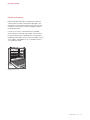
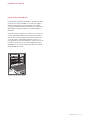
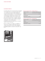
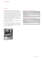
Product Information
Important product information, including the model and
serial number, are listed on the product rating plate. The
rating plate is located near the bottom trim on the left. The
oven door must be open to view the rating plate. Refer to
the illustration below.
If service is necessary, contact Wolf Factory Certied
Service with the model and serial number. For the name of
the nearest Wolf Factory Certied Service or for questions
regarding the installation, visit the contact & support section
of our website, wolfappliance.com, or call Wolf customer
care at 800-222-7820.
Rating plate location
RATING
PLATE

4
|
Wolf Customer Care 800.222.7820
SPECIFICATIONS
Installation Requirements
The M series oven can be installed in a standard or ush
inset application. If a cooktop is being installed above an
oven, a minimum of
1
/4" (6) is required between units. Loca-
tion of the electrical supply within the oven opening may
require additional cabinet depth.
Finish the edges of the opening. They may be visible when
the door is open.
For standard installations, the face trim overlaps stiles and
rails. Refer to the chart below.
For ush inset installations, a minimum
1
/8" (3) reveal is
required on all sides. To ensure consistent reveals, each
corner of the opening must be exactly 90°.
INSTALLATION REQUIREMENTS
BASE SUPPORT MIN
Single Oven 250 lb (115 kg)
Double Oven 400 lb (181 kg)
TRIM OVERLAP
Top 1" (25)
Bottom 0" (0)
Sides
11
/16" (18)
DUAL INSTALLATION
Two 30" single M series ovens can be installed side by side
in a standard or ush inset application. A dual installation kit
is required. To maintain appropriate airow, the ovens must
be installed into one opening. Any cosmetic or structural
material placed between the ovens will impede airow and
is not recommended. Refer to illustrations on the following
pages.
The dual installation kit is available through an authorized
Wolf dealer. For local dealer information, visit the nd a
showroom section of our website, wolfappliance.com.

wolfappliance.com
|
5
Electrical Requirements
Installation must comply with all applicable electrical codes.
Locate the electrical supply ush with the back wall and
within the shaded area shown in the illustrations on the
following pages. For ease of installation, the electrical
supply for the oven can be placed in an adjacent cabinet
within reach of the conduit.
Performance may be compromised if the electrical supply is
less than 240 volts.
The oven is supplied with a conduit consisting of two
insulated hot lead conductors and a bare ground conductor.
The wiring diagram covering the control circuit is provided
with the oven.
Rating plate location
RATING
PLATE
SPECIFICATIONS
ELECTRICAL REQUIREMENTS—SINGLE OVEN
Electrical Supply grounded, 240/208 VAC, 60 Hz
Service 30 amp dedicated circuit
Conduit 4'
(1.2 m)
Total Amps 22
Max Connected Load 5.4 kW
ELECTRICAL REQUIREMENTS —DOUBLE OVEN
Electrical Supply grounded, 240/208 VAC, 60 Hz
Service 50 amp dedicated circuit
Conduit 5'
(1.5 m)
Total Amps 45
Max Connected Load 10.8 kW

6
|
Wolf Customer Care 800.222.7820
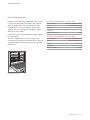
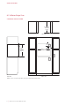
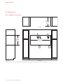
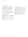
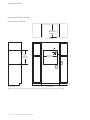
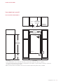
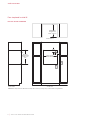
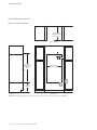
SPECIFICATIONS
30" M Series Single Oven
STANDARD INSTALLATION
28
1
/2" (724)
OPENING WIDTH
E
5"
(127)
E
E
4"
(102)
FRONT VIEW
SIDE
VIEW
NOTE: Location of electrical supply within opening may require additional cabinet depth.
23
1
/4" (591)
OPENING
DEPTH
TOP VIEW
27
1
/2"
(699)
OPENING
HEIGHT

wolfappliance.com
|
7
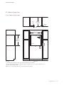
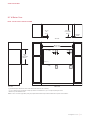
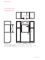
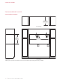
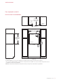
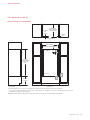
SPECIFICATIONS
30" M Series Single Oven
FLUSH INSET INSTALLATION
30
1
/8" (765)
FLUSH INSET WIDTH***
*1
" (25) minimum depth. Shaded areas will be visible and should be finished to match cabinetry.
**
7
/8" (22) for transitional, professional and contemporary stainless steel models and 1" (25) for contemporary black glass model.
**
*Dimension provides minimum reveals.
NOTE: Location of electrical supply within opening may require additional cabinet depth.
28
3
/4"
(730)
FLUSH INSET
HEIGHT***
E
5"
(127)
4"
(102)
FRONT VIEW
SIDE
VIEW
1
1
/8" (29)
1
/8" (3)
13
/16" (21)
24" (610)
FLUSH INSET
DEPTH
7
/
8
"
(22)
OR
1"
(25)**
TOP VIEW
E
E
FINISHED
CLEATS*

8
|
Wolf Customer Care 800.222.7820
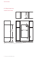
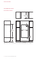
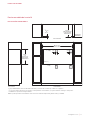
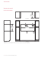
SPECIFICATIONS
30" M Series Double Oven
STANDARD INSTALLATION
28
1
/2" (724)
OPENING WIDTH
E
5"
(127)
4"
(102)
E
E
FRONT VIEW
SIDE
VIEW
NOTE: Location of electrical supply within opening may require additional cabinet depth.
49
7
/
8
"
(1267)
OPENING
HEIGHT
23
1
/4" (591)
OPENING
DEPTH
17" (432)
TYPICAL
TOP VIEW

wolfappliance.com
|
9
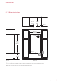
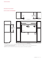
SPECIFICATIONS
30" M Series Double Oven
FLUSH INSET INSTALLATION
30
1
/8" (765)
FLUSH INSET WIDTH***
*1
" (25) minimum depth. Shaded areas will be visible and should be finished to match cabinetry.
**
7
/8" (22) for transitional, professional and contemporary stainless steel models and 1" (25) for contemporary black glass model.
**
*Dimension provides minimum reveals.
NOTE: Location of electrical supply within opening may require additional cabinet depth.
E
5"
(127)
4"
(102)
FRONT VIEW
SIDE
VIEW
51
1
/
8
"
(1299)
FLUSH INSET
HEIGHT***
1
1
/8" (29)
1
/8" (3)
13
/16" (21)
24" (610)
FLUSH INSET
DEPTH
7
/
8
"
(22)
OR
1"
(25)**
17"
(432)
TYPICAL
TOP VIEW
E
E
FINISHED
CLEATS*

10
|
Wolf Customer Care 800.222.7820
E
5"
(127)
E E
4"
(102)
E
5"
(127)
4"
(102)
FRONT VIEW
SIDE
VIEW
NOTE: Location of electrical supply within opening may require additional cabinet depth. A dual installation kit is required fo
r this installation.
23
1
/4" (591)
OPENING
DEPTH
TOP VIEW
27
1
/2"
(699)
OPENING
HEIGHT
58
1
/2" (1486)
OPENING WIDTH
30" M Series Oven
DUAL STANDARD INSTALLATION
SPECIFICATIONS

wolfappliance.com
|
11
E
5"
(127)
4"
(102)
E
5"
(127)
4"
(102)
FRONT VIEW
SIDE
VIEW
*1
" (25) minimum depth. Shaded areas will be visible and should be finished to match cabinetry.
**
7
/8" (22) for transitional, professional and contemporary stainless steel models and 1" (25) for contemporary black glass model.
**
*Dimension provides minimum reveals.
NOTE: Location of electrical supply within opening may require additional cabinet depth. A dual installation kit is required fo
r this installation.
28
3
/4"
(730)
FLUSH INSET
HEIGHT***
1
1
/8" (29)
1
/8" (3)
13
/16" (21)
24" (610)
FLUSH INSET
DEPTH
7
/
8
"
(22)
OR
1"
(25)**
60
1
/8" (1527)
FLUSH INSET WIDTH***
TOP VIEW
EE
FINISHED
CLEATS*
30" M Series Oven
DUAL FLUSH INSET INSTALLATION
SPECIFICATIONS

12
|
Wolf Customer Care 800.222.7820
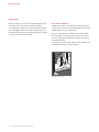
OVEN DOOR REMOVAL
To lighten the load, the oven door(s) can be removed. Only
remove if necessary. Door removal should only be done by a
certied installer or service technician.
To remove, open the door completely. Rotate both hinge
latches forward to the open position, remove each screw
closest to the hinge, then lift the door up and out. Refer to
the illustration below.
To reinstall, insert door hinges into the frame openings, then
rotate hinge latches to the closed position.
Preparation
Before moving the oven, protect any nished ooring and
secure the oven door(s) closed to prevent damage.
Use an appliance dolly to move the oven near the opening.
Place the appliance dolly on the side or back to prevent
damage. Remove and recycle packing materials. Do not lift
or carry the oven by the door handle.
INSTALLATION
CLOSED
OPEN
SCREW
Oven door removal

wolfappliance.com
|
13
Electrical Connection
WARNING
Verify power is disconnected from the electrical box
before proceeding.
If the electrical supply is located in the opening, electrical
connection must be made prior to placing the oven in the
opening. If the electrical supply is in an adjacent cabinet,
electrical connection can be made after placing the oven in
the opening. The conduit on the back of the unit allows for
a 3-wire or 4-wire installation.
1 Connect the black appliance wire to the black (L1)
power supply.
2 Connect the red appliance wire to the red (L2) power
supply.
3 Connect the bare appliance wire to the green/ground
wire.
4 For a four-wire system, seal the white/neutral wire with
a wire cap.
INSTALLATION
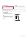
Installation
Place the oven in the opening and slide into position. To
ensure adequate depth for proper installation, the conduit
must t into the recessed area along the rear edge of the
oven.
Locate the mounting hole in each side trim. Drill
1
/16" (2) pilot
holes and install #6 x
3
/4" screws. Refer to the illustration
below.
Remove and recycle packing materials including the white
protective material behind each rack guide mounting
location.
MOUNTING
HOLE
Mounting hole

14
|
Wolf Customer Care 800.222.7820
Troubleshooting
IMPORTANT NOTE: If the oven does not operate properly,
follow these troubleshooting steps:
• Verify electrical power is supplied to the oven.
• Verify proper electrical connections.
• If the oven does not operate properly, contact Wolf Fac-
tory Certied Service. Do not attempt to repair the oven.
Wolf is not responsible for service required to correct a
faulty installation.
TROUBLESHOOTING

Sub-Zero, Sub-Zero & Design, Sub-Zero & Snowake Design, Dual Refrigeration, The Living Kitchen, Great American Kitchens The Fine Art of Kitchen Design, Wolf, Wolf &
Design, Wolf Gourmet, W & Design, red colored knobs, Cove, and Cove & Design are registered trademarks and service marks of Sub-Zero Group, Inc. and its subsidiaries.
All other trademarks are property of their respective owners in the United States and other countries.

2
|
Atención al cliente de Wolf 800.222.7820
HORNO DE LA SERIE M
Contenido
3 Horno de la serie M
4 Especicaciones
12 Instalación
14 Resolución de problemas
Las características y especicaciones están sujetas a cam-
bios sin previo aviso. Visite wolfappliance.com/specs para
obtener la información más actualizada.
Aviso importante
Para garantizar que este producto se instale y opere de
la forma más segura y eciente posible, tome nota de los
siguientes tipos de información resaltada en esta guía:
AVISO IMPORTANTE señala la información que es especial-
mente importante.
PRECAUCIÓN indica una situación en la que se pueden
sufrir heridas leves o provocar daños al producto si no se
siguen las instrucciones.
ADVERTENCIA indica peligro de que se produzcan heridas
graves o incluso la muerte si no se siguen las precauciones.
AVISO IMPORTANTE: en toda esta guía, las dimensiones
entre paréntesis son milímetros, a menos que se especi-
que lo contrario.
AVISO IMPORTANTE: guarde estas instrucciones para el
inspector eléctrico local.

wolfappliance.com
|
3
HORNO DE LA SERIE M
Información del producto
La información importante del producto, incluido el modelo
y número de serie de la unidad, se encuentra en la placa
de datos del producto. La placa de datos se encuentra
cerca de la moldura inferior. La puerta del horno debe estar
abierta para ver la placa de datos. Consulte la siguiente
ilustración.
Si necesita servicio, póngase en contacto con el centro de
servicio autorizado de Wolf y tenga a la mano el modelo y
número de serie de la unidad. Para obtener los datos del
centro de servicio autorizado de Wolf más cercano o si
tiene preguntas acerca de la instalación, visite la sección de
contacto y soporte técnico en nuestra página de Internet
wolfappliance.com o llame a la línea de atención al cliente
de Wolf al 800-222-7820.
Ubicación de la placa de datos
PLACA DE
DATOS

4
|
Atención al cliente de Wolf 800.222.7820
ESPECIFICACIONES
Requisitos de instalación
El horno se puede instalar en una aplicación estándar o
empotrable. Si se instala una estufa sobre el horno, se
requiere un espacio mínimo de
1
/4" (6) entre las unidades.
Es posible que la ubicación del suministro eléctrico al inte-
rior de la abertura del horno requiera de un gabinete
de mayor profundidad. Consulte la tabla siguiente.
Dé el acabado a los bordes de la abertura. Pueden ser visi-
bles cuando la puerta está abierta.
Para las instalaciones empotrables se requiere un margen
mínimo de
1
/8" (3) en todos los lados. Para asegurarse de
tener un margen uniforme de
1
/8" (3), cada esquina de la
abertura debe tener exactamente 90°.
REQUISITOS DE INSTALACIÓN
SOPORTE DE LA BASE MIN
Horno sencillo 250 lb (115 kg)
Horno doble 400 lb (181 kg)
SUPERPOSICIÓN DEL RIBETE
Parte superior 1" (25)
Parte inferior 0" (0)
Laterales
11
/16" (18)
INSTALACIÓN DOBLE
Se pueden instalar dos hornos 30" sencillo de la serie M,
uno junto al otro, en una aplicación estándar o empotrable.
Se requiere kit de instalación doble. Para mantener un ujo
de aire adecuado, los hornos se deben instalar en una sola
abertura. Cualquier elemento cosmético o estructural que
se coloque entre los hornos obstruirá el ujo de aire y, por
lo tanto, no se recomienda. Consulte las ilustraciones de las
páginas siguientes.
El kit de instalación doble está disponible a través de un
distribuidor autorizado de Wolf. Para obtener más infor-
mación acerca de los distribuidores locales, visite la
sección de salas de exposiciones de nuestro sitio web,
wolfappliance.com.

wolfappliance.com
|
5
Instalación eléctrica
La instalación debe tener una conexión a tierra de conformidad
con los códigos locales o, en ausencia de códigos locales,
con el Código Nacional de Electricidad, ANSI/NFPA 70.
Coloque el suministro eléctrico a ras con la pared posterior
y dentro del área sombreada que se muestra en la ilustra-
ción de las páginas siguientes para su instalación espe-
cíca. Para facilitar la instalación, el suministro eléctrico
para el horno se puede colocar en un gabinete adyacente
al alcance del conducto. Utilice únicamente el conducto
suministrado con este electrodoméstico.
El rendimiento puede verse comprometido si el suministro
eléctrico es menor a 240 voltios.
El horno se entrega con un conducto con cableado con-
sistente en dos conductores aislados para energía y un
conductor desnudo para conexión a tierra. El diagrama
de cableado que abarca el circuito de control viene con el
horno.
Ubicación de la placa de datos
PLACA DE
DATOS
ESPECIFICACIONES
REQUISITOS ELÉCTRICOS—HORNO SENCILLO
Suministro eléctrico Aterrizado, 240/208 VAC, 60 Hz
Servicio Circuito dedicado de 30 amperes
Conducto 4'
(1.2 m)
Total de amperes 22
Carga máxima conectada 5.4 kW
REQUISITOS ELÉCTRICOS—HORNO DOBLE
Suministro eléctrico Aterrizado, 240/208 VAC, 60 Hz
Servicio Circuito dedicado de 50 amperes
Conducto 5'
(1.5 m)
Total de amperes 45
Carga máxima conectada 10.8 kW

6
|
Atención al cliente de Wolf 800.222.7820
E
E
E
VISTA FRONTAL
VIST
A LATERAL
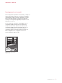
NOTA: es posible que la ubicación del suministro eléctrico al interior de la abertura requiera de un gabinete de mayor profundi
dad.
27
1
/2"
(699)
ALTURA DE
LA ABERTURA
23
1
/4" (591)
PROFUNDIDAD DE
LA ABERTURA
VISTA SUPERIOR
28
1
/
2
"
(724)
ANCHURA DE LA ABERTURA
5"
(127)
4"
(102)
ESPECIFICACIONES
Horno sencillo de la serie M
INSTALACIÓN ESTÁNDAR
A página está carregando ...
A página está carregando ...
A página está carregando ...
A página está carregando ...
A página está carregando ...
A página está carregando ...
A página está carregando ...
A página está carregando ...
A página está carregando ...
A página está carregando ...
A página está carregando ...
A página está carregando ...
A página está carregando ...
A página está carregando ...
A página está carregando ...
A página está carregando ...
A página está carregando ...
A página está carregando ...
A página está carregando ...
A página está carregando ...
A página está carregando ...
A página está carregando ...
A página está carregando ...
A página está carregando ...
-
 1
1
-
 2
2
-
 3
3
-
 4
4
-
 5
5
-
 6
6
-
 7
7
-
 8
8
-
 9
9
-
 10
10
-
 11
11
-
 12
12
-
 13
13
-
 14
14
-
 15
15
-
 16
16
-
 17
17
-
 18
18
-
 19
19
-
 20
20
-
 21
21
-
 22
22
-
 23
23
-
 24
24
-
 25
25
-
 26
26
-
 27
27
-
 28
28
-
 29
29
-
 30
30
-
 31
31
-
 32
32
-
 33
33
-
 34
34
-
 35
35
-
 36
36
-
 37
37
-
 38
38
-
 39
39
-
 40
40
-
 41
41
-
 42
42
-
 43
43
-
 44
44


Sub-Zero DO30CM/B Guia de instalação
- Categoria
- Microondas
- Tipo
- Guia de instalação
- Este manual também é adequado para
em outros idiomas
- español: Sub-Zero DO30CM/B Guía de instalación
- français: Sub-Zero DO30CM/B Guide d'installation