
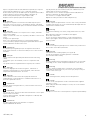
Symbols
To allow quick and easy consultation, this manual uses graphic
symbols to highlight situations in which maximum care is required,
as well as practical advice or information.
Pay attention to the meaning of the symbols since they serve to
avoid repeating technical concepts or safety warnings throughout
the text. The symbols should therefore be seen as real reminders.
Please refer to this page whenever in doubt as to their meaning.
Warning
Failure to follow these instructions might give raise to a dangerous
situation and provoke severe personal injuries or even death.
Caution
Failure to follow these instructions might cause damages to the
vehicle and/or its components.
Notes
Useful information on the procedure being described.
References
Parts highlighted in grey and with a numeric reference
(Example
1
) are the accessory to be installed and any assembly
components supplied with the kit.
Parts with an alphabetic reference (Example
A
) are the original
components fitted on the vehicle.
Any right- or left-hand indication refers to the vehicle direction of
travel.
General notes
Warning
Carefully perform the operations on the following pages since they
might negatively affect rider safety.
Warning
Carefully perform the operations on the following pages since they
might negatively affect rider safety.
Notes
The following documents are necessary for assembling the Kit:
WORKSHOP MANUAL of your bike model.
Notes
Should it be necessary to change any kit parts, please refer to the
attached spare part table.
Simbologia
Per una lettura rapida e razionale sono stati impiegati simboli che
evidenziano situazioni di massima attenzione, consigli pratici o
semplici informazioni.
Prestare molta attenzione al significato dei simboli, in quanto la
loro funzione è quella di non dovere ripetere concetti tecnici o
avvertenze di sicurezza. Sono da considerare, quindi, dei veri e
propri “promemoria”.
Consultare questa pagina ogni volta che sorgeranno dubbi sul loro
significato.
Attenzione
La non osservanza delle istruzioni riportate può creare una
situazione di pericolo e causare gravi lesioni personali e anche la
morte.
Importante
Indica la possibilità di arrecare danno al veicolo e/o ai suoi
componenti se le istruzioni riportate non vengono eseguite.
Note
Fornisce utili informazioni sull’operazione in corso.
Riferimenti
I particolari evidenziati in grigio e riferimento numerico (Es.
1
)
rappresentano l’accessorio da installare e gli eventuali componenti
di montaggio forniti a kit.
I particolari con riferimento alfabetico (Es.
A
) rappresentano i
componenti originali presenti sul motoveicolo.
Tutte le indicazioni destro o sinistro si riferiscono al senso di marcia
del motociclo.
Avvertenze generali
Attenzione
Le operazioni riportate nelle pagine seguenti devono essere
eseguite da un tecnico specializzato o da un’officina autorizzata
DUCATI.
Attenzione
Le operazioni riportate nelle pagine seguenti se non eseguite a
regola d’arte possono pregiudicare la sicurezza del pilota.
Note
Documentazione necessaria per eseguire il montaggio del Kit
è il MANUALE OFFICINA, relativo al modello di moto in vostro
possesso.
Note
Nel caso fosse necessaria la sostituzione di un componente del kit
consultare la tavola ricambi allegata.
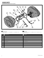
Kit borse laterali
96781131A (Red) - 96781141A (Star white silk)
Side pannier kit
96781131A (Red) - 96781141A (Star white silk)
1
ISTR - 867 / 00

Warning
The side panniers kit is not compatible with the complete racing
exhaust assembly kit.
Attenzione
Il kit borse laterali non è compatibile con il kit gruppo scarico
completo racing.
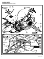
Pos. Denominazione Description
1
Borsa destra RH side pannier
2
Borsa sinistra LH side pannier
3
Telaietto Sub-frame
4
Puntone sinistro LH linkage
5
Puntone destro RH linkage
6
Vite speciale Special screw
7
Distanziale con collare Spacer with collar
8
Vite TCEIF M8X45 TCEIF screw M8x45
9
Vite TCEIF M6x18 TCEIF screw M6x18
10
Rosetta Washer
11
Vite TCEIF M8X25 TCEIF screw M8X25
2
ISTR 867 / 00
8 5
7676
910
93
11 4
1
11 2

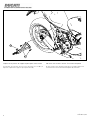
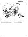
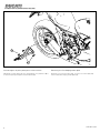
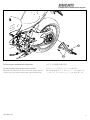
Removing the original components
Removing rear LH footpeg holder plate
Working on motorcycle's LH side, loosen no.2 screws (A1) and
remove rear LH footpeg holder plate (A).
Smontaggio componenti originali
Smontaggio piastra portapedana posteriore sinistra
Operando sul lato sinistro del motoveicolo, svitare le n.2 viti (A1) e
rimuovere la piastra portapedana posteriore sinistra (A).
3
ISTR 867 / 00
A1
A

Removing rear RH footpeg holder plate
Working on motorcycle's RH side, loosen no.2 screws (B1) and
remove rear RH footpeg holder plate (B).
Smontaggio piastra portapedana posteriore destra
Operando sul lato destro del motoveicolo, svitare le n.2 viti (B1) e
rimuovere la piastra portapedana posteriore destra (B).
4
ISTR 867 / 00
B1
B

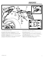
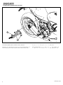
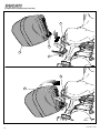
Removing the number plate holder unit
Remove plug (C1) on the lower part of number plate holder unit
(C), as shown in box (X).
Loosen no.4 screws (C2) with no.4 washers (C3) and release
number plate holder unit (C), without removing it, paying attention
not to damage wiring (C4).
Remove no.2 spacers (C5) installed on no.2 front vibration
dampers (C6) of number plate holder (C), as shown in box (Y).
Collect no.2 screws (C2) and no.2 washers (C3).
Smontaggio gruppo portatarga
Rimuovere il tappo (C1) posto nel parte inferiore del gruppo
portatarga (C), come mostrato nel riquadro (X).
Svitare le n.4 viti (C2) con n.4 rosette (C3) e svincolare il gruppo
portatarga (C), senza rimuoverlo, prestando attenzione a non
danneggiare il cablaggio (C4).
Rimuovere i n.2 distanziali (C5) inseriti sui n.2 gommini antivibranti
(C6) anteriori del portatarga (C), come mostrato nel riquadro (Y).
Recuperare le n.2 viti (C2) e le n.2 rosette (C3).
5
ISTR 867 / 00
C
C5
C6
C5
C1
X
Y
C1
C3
C3
C2
C3C4
C2
C3
C2

Kit installation
Caution
Check that all components are clean and in perfect condition
before installation.
Adopt any precaution necessary to avoid damages to any part of
the motorcycle you are working on.
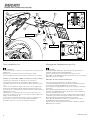
Refitting the number plate holder unit
Fit no.2 spacers with collar (7) on no.2 front vibration dampers (C6)
of number plate holder unit (C), aiming them as shown in figure (J).
Insert no.2 original washers (C3) on no.2 original screws (C2).
Position number plate holder unit (C) under rear subframe (D)
having care not to squeeze rear wiring (C4).
Start no.2 special screws (6) on the front holes and no.2 screws
(C2) with no.2 washers (C3) on the rear holes of number plate
holder unit (C).
Tighten no.2 special screws (6) and no.2 screws (C2) to the
specified torque.
Fit plug (C1) on number plate holder unit (C) as shown in box (K).
Montaggio componenti kit
Importante
Verificare, prima del montaggio, che tutti i componenti risultino
puliti e in perfetto stato.
Adottare tutte le precauzioni necessarie per evitare di danneggiare
qualsiasi parte nella quale ci si trova ad operare.
Rimontaggio gruppo portatarga
Montare i n.2 distanziali con collare (7) sui n.2 gommini antivibranti
(C6) anteriori del gruppo portatarga (C), orientandoli come mostrato
in figura (J).
Inserire le n.2 rosette originali (C3) sulle n.2 viti originali (C2).
Posizionare il gruppo portatarga (C) al di sotto del telaietto
posteriore (D) prestando attenzione a non schiacciare il cablaggio
posteriore (C4).
Impuntare le n.2 viti speciali (6) sui fori anteriori e le n.2 viti (C2)
con n.2 rosette (C3) sui fori posteriori del gruppo portatarga (C).
Serrare le n.2 viti speciali (6) e le n.2 viti (C2) alla coppia indicata.
Montare il tappo (C1) sul gruppo portatarga (C) come mostrato nel
riquadro (K)
6
ISTR 867 / 00
C
D
7
C1
K
J
C1
C3
C3
7
C6
6
C2
C4
6
20 Nm ± 10%
20 Nm ± 5%

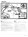
Fitting subframe
Position subframe (3) on number plate holder unit (C), aiming it as
shown in the figure, and start no.2 screws (8) without tightening.
Montaggio telaietto
Posizionare il telaietto (3) sul gruppo portatarga (C), orientandolo
come mostrato in figura e impuntare senza serrare le n.2 viti (8).
7
ISTR 867 / 00
3
C
8

8
ISTR 867 / 00
A
10
3
5
4
9
10
B 5
4
3
11
11
8
9
10 Nm ± 10%
D
10 Nm ± 10%
30 Nm ± 5%
20 Nm ± 10%
30 Nm ± 5%
2
1
4
3
5
7
6
8
Z

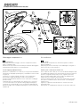
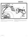
Refitting rear LH footpeg holder plate
Apply LOCTITE 243 on the thread of no. 2 screws (11).
Working on motorcycle’s LH side, position rear LH plate (A) on rear
subframe (D), placing LH linkage (4) in-between, as shown in the
figure, and start no.2 screws (11).
Refitting rear RH footpeg holder plate
Apply LOCTITE 243 on the thread of no. 2 screws (11).
Working on motorcycle’s RH side, position rear RH plate (B) on rear
subframe (D), placing RH linkage (5) in-between, as shown in the
figure, and start no.2 screws (11).
Fitting subframe unit
Fasten LH linkage (4) and RH linkage (5) to subframe (3) starting
no.2 screws (9) with no.2 washers (10), as shown in box (Z).
Tightening subframe unit
Tighten screws (8), (9) and (11) to the specified torque, following
the sequence shown in the figure.
Rimontaggio piastra portapedana posteriore sinistra
Applicare LOCTITE 243 sul filetto delle n.2 viti (11).
Operando sul lato sinistro del motoveicolo, posizionare la piastra
posteriore sinistra (A) sul telaietto posteriore (D), interponendo il
puntone sinistro (4), come mostrato in figura e impuntare le n.2 viti
(11).
Rimontaggio piastra portapedana posteriore destra
Applicare LOCTITE 243 sul filetto delle n.2 viti (11).
Operando sul lato destro del motoveicolo, posizionare la piastra
posteriore destra (B) sul telaietto posteriore (D), interponendo il
puntone destro (5), come mostrato in figura e impuntare le n.2 viti
(11).
Assemblaggio gruppo telaietto
Fissare il puntone sinistro (4) e il puntone destro (5) al telaietto (3)
impuntando le n.2 viti (9) con le n.2 rosette (10), come mostrato
nel riquadro (Z).
Serraggio gruppo telaietto
Serrare le viti (8), (9) e (11) alla coppia indicata, rispettando la
sequenza mostrata in figura.
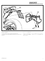
9
ISTR 867 / 00

10
ISTR 867 / 00
2
3A
2A
3
3B
2B

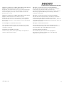
Lay left pannier (2) lower retainers (2A) onto subframe (3) lower
support (3A), as shown in the figure.
Turn wrench so as to release the upper retainer (2B) and hook
pannier to subframe (3) upper support (3B).
Turn wrench to lock upper retainer (2B).
Repeat the same procedure for RH side pannier (1).
Warning
Always respect the speed limits in force in the country where bike
is ridden and, anyway, do not exceed 130 Km/h (80 mph) with the
side panniers installed on bike.
Warning
To clean the side bags, use warm, soapy water and a soft, clean
cloth.
Bar soap and a soft brush is suitable for the zippers.
Rinse with clean water.
Do not use strong cleaning agent or rough cleaningutensils.
Hard to open zipper can be loosened whit a small amount of
talcum powder.
Caution
Continuous and prolonged exposure to weather may create minor
discoloration in the fabrics/materials.
Warning
Side pannier max. loading capacity is 5 Kg (11 lb).
Should this weight be exceeded, panniers could break.
This can affect rider's safety.
Warning
Arrange luggage evenly and keep the heaviest items to the inside
of the bag, so as to avoid unexpected unbalance of the vehicle.
Warning
Failure to observe weight limits could result in poor handling
and impair the performance of your motorcycle, and you may los
control of the motorcycle.
Caution
When washing the bike, always remove side panniers.
Caution
In case of rain, side panniers can be covered with the supplied
waterproof covers.
When riding the bike with waterproof covers, do not exceed 110
Km/h (68 mph).
Caution
Waterproof covers do not ensure pannier complete impermeability.
Appoggiare gli agganci inferiori (2A) della borsa sinistra (2) al
supporto inferiore (3A) del telaietto (3), come indicato in figura.
Ruotare la chiave in posizione di sblocco dell'aggancio superiore
(2B) e agganciare la borsa al supporto superiore (3B) del telaietto
(3).
Ruotare la chiave per bloccare l'aggancio superiore (3B).
Ripetere la stessa operazione per la borsa destra (1).
Attenzione
È fatto obbligo di rispettare i limiti di velocità imposti dal paese in
cui ci si trova a circolare e comunque è vietato oltrepassare
i 130 Km/h (80 mph) con le borse laterali montate sulla moto.
Attenzione
Pulire le borse laterali con uno straccio morbido e pulito utilizzando
acqua tiepida e sapone.
Pulire le chiusure lampo con una saponetta e una spazzola
morbida.
Risciacquare con acqua pulita.
Evitare l'uso di agenti aggressivi o attrezzi ruvidi.
Se necessario, applicare una piccola quantità di talco per facilitare
l'apertura delle chiusure lampo.
Importante
La continua e prolungata esposizione agli agenti atmosferici
potrebbe determinare dei minimi o sensibili cambiamenti nel
colore dei tessuti/materiali.
Attenzione
Il peso massimo trasportabile dalle borse laterali è di 5 Kg (11 lb).
Nel caso si ecceda il peso consigliato si rischia la rottura delle
borse stesse.
Questo puo’ influire negativamente sulla sicurezza del pilota.
Attenzione
Sistemare i bagagli in modo omogeneo, tenendo gli elementi
più pesanti verso l'interno della borsa, onde evitare imprevedibili
sbilanciamenti del veicolo.
Attenzione
Il mancato rispetto dei limiti di carico potrebbe influenzare
negativamente la maneggevolezza e la resa del vostro motoveicolo
e potrebbe causarne la perdita di controllo.
Importante
Quando si effettua il lavaggio della moto è necessario rimuovere le
borse laterali.
Importante
In caso di pioggia è possibile ricoprire le borse laterali con le cuffie
impermeabili in dotazione.
Con la cuffie montate è vietato oltrepassare i 110 Km/h (68 mph) di
velocità.
Importante
Le cuffie impermeabili non garantiscono la completa
impermeabilità delle borse.
11
ISTR 867 / 00

NOTE / NOTES
1 P/N 商品名
2 P/N 商品名
3 P/N 商品名
4 P/N 商品名
5 P/N 商品名
ご注文商品
レース専用部品 ご注文書
DUCATI PERFORMANCE
accessories
モデル名
ご注文日
販売日 年 月 日
1.
上記
ご
記入
の
上
、
弊社
アフターセールス
部
まで
FAX
してください
。
FAX
:
03
-
6692
-
1317
お客様ご記入欄
私は上記レース専用部品を下記車両に装着し、サーキット走行のみに
利用し、一般公道には利用しません。
販売店署名
販売店様へお願い
車台番号 ZDM
お客様署名
ドゥカティ正規ネットワーク店記入欄
お客様に上記レース専用部品を販売し、レース専用部品のご利用方法を
説明いたしました。
1.
上記
ご
記入
の
上
、
弊社
アフターセールス
部
まで
FAX
してください
。
FAX
:
03
-
6692
-
1317
2.
取
り
付
け
車両
1
台
に
1
枚
でご
使用
ください
。
ISTR 867 / 00

Symbole
Zum schnellen und übersichtlichen Lesen werden Symbole
verwendet, die außerordentlich wichtige Situationen, praktische
Ratschläge oder auch nur einfache Informationen hervorheben.
Der Bedeutung dieser Symbole ist besondere Aufmerksamkeit
zu schenken, da sich hierdurch das ständige Wiederholen von
technischen Konzepten oder Sicherheitshinweisen erübrigt. Sie
stellen daher regelrechte „Merker“ dar. Diese Seite ist immer dann
zur Hand zu nehmen, wenn Zweifel über die Bedeutung eines
Symbols bestehen sollten.
Achtung
Eine Nichtbeachtung der hier wiedergegebenen Anweisungen
kann Gefahrensituationen schaffen und zu schweren Verletzungen
und auch zum Tod führen.
Wichtig
Weist darauf hin, dass bei Nichteinhaltung der hier
wiedergegebenen Anweisungen die Möglichkeit für Schäden am
Fahrzeug und/oder seiner Komponenten besteht.
Hinweis
Übermittelt nützliche Informationen zum betreffenden
Arbeitseingriff.
Bezugsangaben
Die grau gekennzeichneten Bestandteile mit numerischem
Bezug (Bsp.
1
) geben das zu installierende Bestandteil und die
eventuellen, im Kit enthaltenen Montagekomponenten wieder.
Die Bestandteile mit alphabetischem Bezug (Bsp.
A
) geben die
Original-Bestandteile wieder, die am Motorrad verbaut wurden.
Alle Angaben wie „rechts” oder „links” beziehen sich auf die
Fahrtrichtung des Motorrads.
Allgemeine Warnhinweise
Achtung
Werden die auf den folgenden Seiten beschriebenen
Arbeitsmaßnahmen nicht fachgerecht ausgeführt, kann sich dies
auf die Sicherheit des Fahrers auswirken.
Achtung
Werden die auf den folgenden Seiten beschriebenen
Arbeitsmaßnahmen nicht fachgerecht ausgeführt, kann sich dies
auf die Sicherheit des Fahrers auswirken.
Hinweis
Für die Montage des Kits sind folgende Unterlagen erforderlich:
WERKSTATTHANDBUCH, des sich in Ihrem Besitz befindlichen
Motorrads.
Hinweis
Sollte sich der Austausch eines Bestandteils des Kits als
erforderlich erweisen, ist dazu Bezug auf die beiliegende
Ersatzteiltafel zu nehmen.
Symboles
Pour faciliter la consultation de ce manuel, des symboles signalent
des situations exigeant le maximum d'attention, des conseils
pratiques ou de simples informations. Lire attentivement la
signification de ces symboles car ils renvoient à des concepts
techniques ou des consignes de sécurité de la plus grande
importance. Ils doivent être considérés comme de véritables «
aide-mémoire ». Toujours consulter cette page en cas de doute
concernant leur signification.
Attention
La non-observance des instructions reportées ci-dessous peut
créer une situation dangereuse et provoquer de graves lésions
personnelles voire la mort.
Important
Indique la possibilité d'endommager le véhicule et/ou ses
composants si les instructions reportées ci-dessous ne sont pas
suivies.
Remarques
Fournit des informations utiles sur l'opération en cours.
Références
Les pièces surlignées en gris et la référence numérique
(Ex.
1
) représentent l'accessoire à installer et les composants de
montage éventuels fournis en kit.
Les pièces avec référence alphabétique (Ex.
A
) représentent les
composants d'origine présents sur le motocycle.
Toutes les indications droite ou gauche se réfèrent au sens de
marche la moto.
Avertissements généraux
Attention
Les opérations indiquées dans les pages suivantes, au cas où
elles ne seraient pas effectuées selon les règles de l'art pourraient
compromettre la sécurité du pilote.
Attention
Les opérations indiquées dans les pages suivantes, au cas où
elles ne seraient pas effectuées selon les règles de l'art pourraient
compromettre la sécurité du pilote.
Remarques
La documentation nécessaire pour effectuer la pose du Kit est
le : MANUEL D'ATELIER, relatif au modèle de moto en votre
possession.
Remarques
Au cas où il serait nécessaire d'effectuer le remplacement d'un
composant du kit, il faudra consulter la planche relative aux pièces
détachées ci-jointe.
Kit valises latérales
96781131A (Red) - 96781141A (Star white silk)
Kit Seitenkoffer
96781131A (Red) - 96781141A (Star white silk)
1
ISTR - 867 / 00

Achtung
Das Kit Seitenkoffer ist nicht mit dem Kit komplette Racing-
Auspuffeinheit kompatibel.
Attention
Le kit valises latérales n’est pas compatible avec le kit système
d’échappement complet racing.
Pos. Designation Bezeichnung
1
Valise droite Koffer, rechts
2
Valise gauche Koffer, links
3
Sous-cadre Heckrahmen
4
Bras de support gauche Linke Abstützung
5
Bras de support droit Rechte Abstützung
6
Vis spéciale Spezialschraube
7
Entretoise à collerette Distanzstück mit Bund
8
Vis TCHCB M8X45 Geflanschte Zylinderschraube mit Innensechskant M8x45
9
Vis TCHCF M6x18 Geflanschte Zylinderschraube mit Innensechskant M6x18
10
Rondelle Unterlegscheibe
11
Vis TCHCF M8X25 Geflanschte Zylinderschraube mit Innensechskant M8x25
2
ISTR 867 / 00
8 5
7676
910
93
11 4
1
11 2

Ausbau der Original-Bestandteile
Abnahme der hinteren linken Fußrastenhalterplatte
An der linken Seite des Motorrads die 2 Schrauben (A1) lösen und
die hintere linke Fußrastenhalterplatte (A) entfernen.
Dépose composants d'origine
Dépose de la platine de support repose-pied arrière gauche
En agissant du côté gauche du motocycle, desserrer les 2 vis (A1)
et déposer la platine de support repose-pied gauche (A).
3
ISTR 867 / 00
A1
A

Abnahme der hinteren rechten Fußrastenhalterplatte
An der rechten Seite des Motorrads die 2 Schrauben (B1) lösen
und die hintere linke Fußrastenhalterplatte (B) entfernen.
Dépose de la platine de support repose-pied arrière droite
En agissant du côté droit du motocycle, desserrer les 2 vis (B1) et
déposer la platine de support repose-pied droit (B).
4
ISTR 867 / 00
B1
B

Abnahme der Kennzeichenhaltereinheit
Den Verschluss (C1) am unteren Teil der Kennzeichenhaltereinheit
(C) gemäß Abbildung (X) entfernen.
Die 4 Schrauben (C2) mit 4 Unterlegscheiben (C3) lösen und die
Kennzeichenhaltereinheit (C) trennen, ohne sie zu entfernen und
dabei darauf achten, dass die Verkabelung (C4) nicht beschädigt
wird.
Die 2 Distanzstücke (C5), die am 2 vorderen
Schwingungsdämpfergummis (C6) des Kennzeichenhalters (C)
angefügt sind, gemäß Abbildung (Y) entfernen.
Die 2 Schrauben (C2) und die 2 Unterlegscheiben (C3) aufnehmen.
Dépose de l'ensemble support de plaque d'immatriculation
Déposer le bouchon (C1) situé dans la partie inférieure de
l'ensemble support de plaque d'immatriculation (C), comme
l’encadré le montre (X).
Desserrer les 4 vis (C2) avec 4 rondelles (C3) et dégager
l'ensemble support de plaque d'immatriculation (C), sans le
déposer, en veillant à ne pas endommager le câblage (C4).
Déposer les 2 entretoises (C5) insérées sur les 2 plots
antivibratoires (C6) avant du support de plaque d'immatriculation
(C), comme l’encadré le montre (Y).
Récupérer les 2 vis (C2) et les 2 rondelles (C3).
5
ISTR 867 / 00
C
C5
C6
C5
C1
X
Y
C1
C3
C3
C2
C3C4
C2
C3
C2

Montage der Komponenten des Kits
Wichtig
Vor der Montage überprüfen, dass sich alle Komponenten im
sauberen und perfekten Zustand befinden.
Alle erforderlichen Vorsichtsmaßnahmen treffen, um eine
Beschädigung der Oberflächen der Komponenten, die vom Eingriff
betroffen sind, zu vermeiden.
Montage der Kennzeichenhaltereinheit
Die 2 Distanzstücke mit Bund (7) an den 2 vorderen
Schwingungsdämpfergummis (C6) der Kennzeichenhaltereinheit
(C) montieren und gemäß Abbildung (J) ausrichten.
Die 2 Original-Unterlegscheiben (C3) auf die 2 Original-Schrauben
(C2) fügen.
Die Kennzeichenhaltereinheit (C) unter dem Heckrahmen (D)
anordnen und dabei darauf achten, dass die hintere Verkabelung
(C4) nicht eingequetscht wird.
Die 2 Spezialschrauben (6) an den vorderen Bohrungen und die 2
Schrauben (C2) mit den 2 Unterlegscheiben (C3) an den hinteren
Bohrungen der Kennzeichenhaltereinheit (C) ansetzen.
Die 2 Spezialschrauben (6) und die 2 Schrauben (C2) mit dem
angegebenen Anzugsmoment anziehen.
Den Verschluss (C1) an der Kennzeichenhaltereinheit (C) gemäß
Abbildung (K) montieren.
Pose composants kit
Important
Vérifier, avant la pose, que tous les composants sont propres et en
parfait état.
Adopter toutes les précautions nécessaires pour éviter
d'endommager la surface externe des composants où on opère.
Repose de l'ensemble support de plaque d'immatriculation
Installer les 2 entretoises à collerette (7) sur les 2 plots
antivibratoires (C6) avant de l'ensemble support de plaque
d'immatriculation (C), en les orientant comme la figure le montre
(J).
Insérer les 2 rondelles d'origine (C3) sur les 2 vis d'origine (C2).
Positionner l'ensemble support de plaque d'immatriculation (C)
au-dessous du sous-cadre arrière (D) en veillant à ne pas écraser le
câblage arrière (C4).
Présenter les 2 vis spéciales (6) sur les trous avant et les 2 vis
(C2) avec 2 rondelles (C3) sur les trous de l'ensemble support de
plaque d'immatriculation (C).
Serrer les 2 vis spéciales (6) et les 2 vis (C2) au couple prescrit.
Poser le bouchon (C1) sur l'ensemble support de plaque
d'immatriculation (C) comme l'encadré le montre (K).
6
ISTR 867 / 00
C
D
7
C1
K
J
C1
C3
C3
7
C6
6
C2
C4
6
20 Nm ± 10%
20 Nm ± 5%

Montage des Heckrahmens
Den Heckrahmen (3) an der Kennzeichenhaltereinheit (C) anordnen,
gemäß Abbildung ausrichten und die 2 Schrauben (8) ansetzen,
ohne sie anzuziehen.
Pose sous-cadre
Positionner le sous-cadre (3) sur le l'ensemble support de plaque
d'immatriculation (C), en l'orientant comme la figure le montre et
présenter les 2 vis (8) sans serrer.
7
ISTR 867 / 00
3
C
8

8
ISTR 867 / 00
A
10
3
5
4
9
10
B 5
4
3
11
11
8
9
10 Nm ± 10%
D
10 Nm ± 10%
30 Nm ± 5%
20 Nm ± 10%
30 Nm ± 5%
2
1
4
3
5
7
6
8
Z
A página está carregando...
A página está carregando...
A página está carregando...
A página está carregando...
A página está carregando...
A página está carregando...
A página está carregando...
A página está carregando...
A página está carregando...
A página está carregando...
A página está carregando...
A página está carregando...
A página está carregando...
A página está carregando...
A página está carregando...
A página está carregando...
A página está carregando...
A página está carregando...
A página está carregando...
A página está carregando...
A página está carregando...
A página está carregando...
A página está carregando...
A página está carregando...
A página está carregando...
A página está carregando...
A página está carregando...
A página está carregando...
A página está carregando...
A página está carregando...
A página está carregando...
-
 1
1
-
 2
2
-
 3
3
-
 4
4
-
 5
5
-
 6
6
-
 7
7
-
 8
8
-
 9
9
-
 10
10
-
 11
11
-
 12
12
-
 13
13
-
 14
14
-
 15
15
-
 16
16
-
 17
17
-
 18
18
-
 19
19
-
 20
20
-
 21
21
-
 22
22
-
 23
23
-
 24
24
-
 25
25
-
 26
26
-
 27
27
-
 28
28
-
 29
29
-
 30
30
-
 31
31
-
 32
32
-
 33
33
-
 34
34
-
 35
35
-
 36
36
-
 37
37
-
 38
38
-
 39
39
-
 40
40
-
 41
41
-
 42
42
-
 43
43
-
 44
44
-
 45
45
-
 46
46
-
 47
47
-
 48
48
-
 49
49
-
 50
50
-
 51
51


Ducati 96781131A Manual do usuário
- Tipo
- Manual do usuário
- Este manual também é adequado para
em outras línguas
- español: Ducati 96781131A Manual de usuario
- français: Ducati 96781131A Manuel utilisateur
- italiano: Ducati 96781131A Manuale utente
- English: Ducati 96781131A User manual
- Deutsch: Ducati 96781131A Benutzerhandbuch
- 日本語: Ducati 96781131A ユーザーマニュアル
Artigos relacionados
-
Ducati 96780571A Manual do usuário
-
-
-
-
-
-
-
-
-