
Symbols
To allow quick and easy consultation, this manual uses graphic
symbols to highlight situations in which maximum care is required,
as well as practical advice or information.
Pay attention to the meaning of the symbols since they serve to
avoid repeating technical concepts or safety warnings throughout
the text. The symbols should therefore be seen as real reminders.
Please refer to this page whenever in doubt as to their meaning.
Warning
Failure to follow these instructions might give raise to a dangerous
situation and provoke severe personal injuries or even death.
Caution
Failure to follow these instructions might cause damages to the
vehicle and/or its components.
Notes
Useful information on the procedure being described.
References
Parts highlighted in grey and with a numeric reference
(Example
1
) are the accessory to be installed and any assembly
components supplied with the kit.
Parts with an alphabetic reference (Example
A
) are the original
components fitted on the vehicle.
Any right- or left-hand indication refers to the vehicle direction of
travel.
General notes
Warning
Carefully perform the operations on the following pages since they
might negatively affect rider safety.
Warning
Carefully perform the operations on the following pages since they
might negatively affect rider safety.
Notes
The following documents are necessary for assembling the Kit:
WORKSHOP MANUAL of your bike model.
Notes
Should it be necessary to change any kit parts, please refer to the
attached spare part table.
Simbologia
Per una lettura rapida e razionale sono stati impiegati simboli che
evidenziano situazioni di massima attenzione, consigli pratici o
semplici informazioni.
Prestare molta attenzione al significato dei simboli, in quanto la
loro funzione è quella di non dovere ripetere concetti tecnici o
avvertenze di sicurezza. Sono da considerare, quindi, dei veri e
propri “promemoria”.
Consultare questa pagina ogni volta che sorgeranno dubbi sul loro
significato.
Attenzione
La non osservanza delle istruzioni riportate può creare una
situazione di pericolo e causare gravi lesioni personali e anche la
morte.
Importante
Indica la possibilità di arrecare danno al veicolo e/o ai suoi
componenti se le istruzioni riportate non vengono eseguite.
Note
Fornisce utili informazioni sull’operazione in corso.
Riferimenti
I particolari evidenziati in grigio e riferimento numerico (Es.
1
)
rappresentano l’accessorio da installare e gli eventuali componenti
di montaggio forniti a kit.
I particolari con riferimento alfabetico (Es.
A
) rappresentano i
componenti originali presenti sul motoveicolo.
Tutte le indicazioni destro o sinistro si riferiscono al senso di marcia
del motociclo.
Avvertenze generali
Attenzione
Le operazioni riportate nelle pagine seguenti devono essere
eseguite da un tecnico specializzato o da un’officina autorizzata
DUCATI.
Attenzione
Le operazioni riportate nelle pagine seguenti se non eseguite a
regola d’arte possono pregiudicare la sicurezza del pilota.
Note
Documentazione necessaria per eseguire il montaggio del Kit
è il MANUALE OFFICINA, relativo al modello di moto in vostro
possesso.
Note
Nel caso fosse necessaria la sostituzione di un componente del kit
consultare la tavola ricambi allegata.
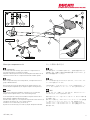
Kit piastra allargamento base cavalletto
Stand extension plate kit
1
Multistrada 1200 ISTR - 661 / 00 97380331A

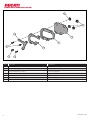
Pos. Denominazione Description
1 Piastra inferiore Lower plate
2 Piastra distanziale Spacer plate
3 Piastra di chiusura inferiore Lower closing plate
4 Piastra di chiusura superiore Upper closing plate
5 Dado speciale Special nut
6 Vite TBEI M5x12 TBEI screw M5x12
7 Vite TBEI M5x10 TBEI screw M5x10
2
ISTR 661 / 00
4
5
6
67
1
2
3
5

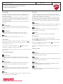
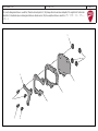
Kit installation
Caution
Check that all components are clean and in perfect condition
before installation.
Adopt any precaution necessary to avoid damages to any part of
the motorcycle you are working on.
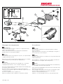
Notes
To better understand how to install the kit, only the side stand unit
will be represented.
Pre-assemble no. 4 special nuts (5) on lower plate (1) and fix the
spacer plate (2) on the upper side of the plate (1) .
Notes
The special nuts (5) must be positioned with the collar (5A) facing
the lower plate, as shown in the figure (X).
Drive the pre-assembled plates fully home in the lower side of the
base (A1) of the stand (A).
From the upper side, position first the lower closing plate (3) and
then the upper closing plate (4), as shown in the figure.
Start no. 3 screws (6) and screw (7).
Tighten no. 3 screws (6) and screw (7) to the specified torque.
Montaggio componenti kit
Importante
Verificare, prima del montaggio, che tutti i componenti risultino
puliti e in perfetto stato.
Adottare tutte le precauzioni necessarie per evitare di danneggiare
qualsiasi parte nella quale ci si trova ad operare.
Note
Per comprendere meglio il montaggio del kit, viene rappresentato
solo il gruppo cavalletto laterale.
Premontare i n.4 dadi speciali (5) sulla piastra inferiore (1) e sulla
parte superiore della piastra (1) montare la piastra distanziale (2).
Note
I dadi speciali (5) devono essere orientati con il collare (5A) rivolto
verso la piastra inferiore, come mostrato in figura (X).
Posizionare le piastre appena premontate nella parte inferiore della
base (A1) del cavalletto (A) fino a battuta.
Dal lato superiore, posizionare prima la piastra di chiusura inferiore
(3) e di seguito quella superiore (4), come mostrato in figura.
Impuntare le n.3 viti (6) e la vite (7).
Serrare le n.3 viti (6) e la vite (7) alla coppia indicata.
3
ISTR 661 / 00
3
6
4
6
7
6
1
2
A
A1
5
5
5
5A12
X
5 Nm ± 10%
5 Nm ± 10%

NOTE / NOTES
1 P/N 商品名
2 P/N 商品名
3 P/N 商品名
4 P/N 商品名
5 P/N 商品名
ご注文商品
レース専用部品 ご注文書
DUCATI PERFORMANCE
accessories
モデル名
ご注文日
販売日 年 月 日
1.
上記
ご
記入
の
上
、
弊社
アフターセールス
部
まで
FAX
してください
。
FAX
:
03
-
6692
-
1317
お客様ご記入欄
私は上記レース専用部品を下記車両に装着し、サーキット走行のみに
利用し、一般公道には利用しません。
販売店署名
販売店様へお願い
車台番号 ZDM
お客様署名
ドゥカティ正規ネットワーク店記入欄
お客様に上記レース専用部品を販売し、レース専用部品のご利用方法を
説明いたしました。
1.
上記
ご
記入
の
上
、
弊社
アフターセールス
部
まで
FAX
してください
。
FAX
:
03
-
6692
-
1317
2.
取
り
付
け
車両
1
台
に
1
枚
でご
使用
ください
。
ISTR 661 / 00

Symbole
Zum schnellen und übersichtlichen Lesen werden Symbole
verwendet, die außerordentlich wichtige Situationen, praktische
Ratschläge oder auch nur einfache Informationen hervorheben.
Der Bedeutung dieser Symbole ist besondere Aufmerksamkeit
zu schenken, da sich hierdurch das ständige Wiederholen von
technischen Konzepten oder Sicherheitshinweisen erübrigt. Sie
stellen daher regelrechte „Merker“ dar. Diese Seite ist immer dann
zur Hand zu nehmen, wenn Zweifel über die Bedeutung eines
Symbols bestehen sollten.
Achtung
Eine Nichtbeachtung der hier wiedergegebenen Anweisungen
kann Gefahrensituationen schaffen und zu schweren Verletzungen
und auch zum Tod führen.
Wichtig
Weist darauf hin, dass bei Nichteinhaltung der hier
wiedergegebenen Anweisungen die Möglichkeit für Schäden am
Fahrzeug und/oder seiner Komponenten besteht.
Hinweis
Übermittelt nützliche Informationen zum betreffenden
Arbeitseingriff.
Bezugsangaben
Die grau gekennzeichneten Bestandteile mit numerischem
Bezug (Bsp.
1
) geben das zu installierende Bestandteil und die
eventuellen, im Kit enthaltenen Montagekomponenten wieder.
Die Bestandteile mit alphabetischem Bezug (Bsp.
A
) geben die
Original-Bestandteile wieder, die am Motorrad verbaut wurden.
Alle Angaben wie „rechts” oder „links” beziehen sich auf die
Fahrtrichtung des Motorrads.
Allgemeine Warnhinweise
Achtung
Werden die auf den folgenden Seiten beschriebenen
Arbeitsmaßnahmen nicht fachgerecht ausgeführt, kann sich dies
auf die Sicherheit des Fahrers auswirken.
Achtung
Werden die auf den folgenden Seiten beschriebenen
Arbeitsmaßnahmen nicht fachgerecht ausgeführt, kann sich dies
auf die Sicherheit des Fahrers auswirken.
Hinweis
Für die Montage des Kits sind folgende Unterlagen erforderlich:
WERKSTATTHANDBUCH, des sich in Ihrem Besitz befindlichen
Motorrads.
Hinweis
Sollte sich der Austausch eines Bestandteils des Kits als
erforderlich erweisen, ist dazu Bezug auf die beiliegende
Ersatzteiltafel zu nehmen.
Symboles
Pour faciliter la consultation de ce manuel, des symboles signalent
des situations exigeant le maximum d'attention, des conseils
pratiques ou de simples informations. Lire attentivement la
signification de ces symboles car ils renvoient à des concepts
techniques ou des consignes de sécurité de la plus grande
importance. Ils doivent être considérés comme de véritables «
aide-mémoire ». Toujours consulter cette page en cas de doute
concernant leur signification.
Attention
La non-observance des instructions reportées ci-dessous peut
créer une situation dangereuse et provoquer de graves lésions
personnelles voire la mort.
Important
Indique la possibilité d'endommager le véhicule et/ou ses
composants si les instructions reportées ci-dessous ne sont pas
suivies.
Remarques
Fournit des informations utiles sur l'opération en cours.
Références
Les pièces surlignées en gris et la référence numérique
(Ex.
1
) représentent l'accessoire à installer et les composants de
montage éventuels fournis en kit.
Les pièces avec référence alphabétique (Ex.
A
) représentent les
composants d'origine présents sur le motocycle.
Toutes les indications droite ou gauche se réfèrent au sens de
marche la moto.
Avertissements généraux
Attention
Les opérations indiquées dans les pages suivantes, au cas où
elles ne seraient pas effectuées selon les règles de l'art pourraient
compromettre la sécurité du pilote.
Attention
Les opérations indiquées dans les pages suivantes, au cas où
elles ne seraient pas effectuées selon les règles de l'art pourraient
compromettre la sécurité du pilote.
Remarques
La documentation nécessaire pour effectuer la pose du Kit est
le : MANUEL D'ATELIER, relatif au modèle de moto en votre
possession.
Remarques
Au cas où il serait nécessaire d'effectuer le remplacement d'un
composant du kit, il faudra consulter la planche relative aux pièces
détachées ci-jointe.
Kit plaque d’extension base béquille
Kit vergrößerte Seitenständerplatte
1
Multistrada 1200 ISTR - 661 / 00 97380331A

Pos. Designation Bezeichnung
1 Plaque inférieure Untere Platte
2 Plaque entretoise Distanzstückplatte
3 Plaque de fermeture inférieure Untere Schließplatte
4 Plaque de fermeture supérieure Obere Schließplatte
5 Écrou spécial Spezialmutter
6 Vis TBHC M5x12 Linseninnensechskantschraube M5x12
7 Vis TBHC M5x10 Linseninnensechskantschraube M5x10
2
ISTR 661 / 00
4
5
6
67
1
2
3
5

Montage der Komponenten des Kits
Wichtig
Vor der Montage überprüfen, dass sich alle Komponenten im
sauberen und perfekten Zustand befinden.
Alle erforderlichen Vorsichtsmaßnahmen treffen, um eine
Beschädigung der Oberflächen der Komponenten, die vom Eingriff
betroffen sind, zu vermeiden.
Hinweis
Zum besseren Verständnis des Kits wird nur die
Seitenständergruppe dargestellt.
Die 4 Spezialmuttern (5) auf der unteren Platte (1) vormontieren
und die Distanzstückplatte (2) auf der oberen Plattenseite (1)
montieren.
Hinweis
Die Spezialmuttern (5) müssen dabei mit dem Bund (5A) zur
unteren Platte gerichtet sein; siehe dazu Abbildung (X).
Die soeben vormontierten Platten an der unteren Fußseite (A1) des
Ständers (A) bis auf Anschlag anordnen.
An der oberen Seite zuerst die untere Schließplatte (3), dann die
obere (4) gemäß Abbildung anordnen.
Die 3 Schrauben (6) und die Schraube (7) ansetzen.
Die 3 Schrauben (6) und die Schraube (7) mit dem angegebenen
Anzugsmoment anziehen.
Pose composants kit
Important
Vérifier, avant la pose, que tous les composants sont propres et en
parfait état.
Adopter toutes les précautions nécessaires pour éviter
d'endommager la surface externe des composants où on opère.
Remarques
Afin de mieux comprendre la pose du kit, on a représenté
uniquement l'ensemble béquille latérale.
Pré-monter les 4 écrous spéciaux (5) sur la plaque inférieure (1) et
sur la partie supérieure de la plaque (1) poser la plaque entretoise
(2).
Remarques
Les écrous spéciaux (5) doivent être orientés avec la collerette (5A)
tournée vers la plaque inférieure, comme la figure (X) le montre.
Positionner les plaques qui viennent d'être pré-montées dans la
partie inférieure de la base (A1) de la béquille (A) jusqu'en butée.
Du côté supérieur, positionner d'abord la plaque de fermeture
inférieure (3) et ensuite celle supérieure (4), comme la figure le
montre.
Présenter les 3 vis (6) et la vis (7).
Serrer les 3 vis (6) et la vis (7) au couple prescrit.
3
ISTR 661 / 00
3
6
4
6
7
6
1
2
A
A1
5
5
5
5A12
X
5 Nm ± 10%
5 Nm ± 10%

REMARQUES / HINWEIS
1 P/N 商品名
2 P/N 商品名
3 P/N 商品名
4 P/N 商品名
5 P/N 商品名
ご注文商品
レース専用部品 ご注文書
DUCATI PERFORMANCE
accessories
モデル名
ご注文日
販売日 年 月 日
1.
上記
ご
記入
の
上
、
弊社
アフターセールス
部
まで
FAX
してください
。
FAX
:
03
-
6692
-
1317
お客様ご記入欄
私は上記レース専用部品を下記車両に装着し、サーキット走行のみに
利用し、一般公道には利用しません。
販売店署名
販売店様へお願い
車台番号 ZDM
お客様署名
ドゥカティ正規ネットワーク店記入欄
お客様に上記レース専用部品を販売し、レース専用部品のご利用方法を
説明いたしました。
1.
上記
ご
記入
の
上
、
弊社
アフターセールス
部
まで
FAX
してください
。
FAX
:
03
-
6692
-
1317
2.
取
り
付
け
車両
1
台
に
1
枚
でご
使用
ください
。
ISTR 661 / 00

Símbolos
Para uma leitura rápida e racional, foram utilizados símbolos que
evidenciam situações de máxima atenção, conselhos práticos ou
simples informações. Preste muita atenção ao significado dos
símbolos, pois a sua função é a de evitar a repetição de conceitos
técnicos ou de avisos de segurança. Portanto, os símbolos devem
ser considerados como verdadeiros "lembretes". Consulte esta
página sempre que tiver dúvidas acerca do seu significado.
Atenção
O não cumprimento das instruções mostradas pode criar uma
situação de perigo e causar graves lesões pessois e até mesmo a
morte.
Importante
Indica a possibilidade de causar danos ao veículo e/ou aos seus
componentes se as instruções mostradas não forem executadas.
Notas
Fornece informações úteis sobre a operação em curso.
Referências
Os detalhes evidenciados em cinza e com referência numérica
(Ex.
1
) representam o acessório a ser instalado e os eventuais
componentes de montagem fornecidos como kit.
Os detalhes com referência alfabética (Ex.
A
) representam os
componentes originais presentes
na moto.
Todas as indicações direita ou esquerda, referem-se ao sentido de
marcha da moto.
Advertências gerais
Atenção
As operações mostradas nas páginas a seguir, se não forem
executadas com boa técnica, podem prejudicar a segurança do
condutor.
Atenção
As operações mostradas nas páginas a seguir, se não forem
executadas com boa técnica, podem prejudicar a segurança do
condutor.
Notas
Documentação necessária para executar a montagem do
Conjunto: MANUAL DE OFICINA, relativo ao modelo de moto em
sua posse.
Notas
Caso seja necessária a substituição de um componente do
conjunto, consulte o quadro de peças de reposição em anexo.
Conjunto de placa de alargamento base do descanso
Stand extension plate kit
Symbols
To allow quick and easy consultation, this manual uses graphic
symbols to highlight situations in which maximum care is required,
as well as practical advice or information.
Pay attention to the meaning of the symbols since they serve to
avoid repeating technical concepts or safety warnings throughout
the text. The symbols should therefore be seen as real reminders.
Please refer to this page whenever in doubt as to their meaning.
Warning
Failure to follow these instructions might give raise to a dangerous
situation and provoke severe personal injuries or even death.
Caution
Failure to follow these instructions might cause damages to the
vehicle and/or its components.
Notes
Useful information on the procedure being described.
References
Parts highlighted in grey and with a numeric reference
(Example
1
) are the accessory to be installed and any assembly
components supplied with the kit.
Parts with an alphabetic reference (Example
A
) are the original
components fitted on the vehicle.
Any right- or left-hand indication refers to the vehicle direction of
travel.
General notes
Warning
Carefully perform the operations on the following pages since they
might negatively affect rider safety.
Warning
Carefully perform the operations on the following pages since they
might negatively affect rider safety.
Notes
The following documents are necessary for assembling the Kit:
WORKSHOP MANUAL of your bike model.
Notes
Should it be necessary to change any kit parts, please refer to the
attached spare part table.
1
Multistrada 1200 ISTR - 661 / 00 97380331A

Pos. Descrição Description
1 Placa inferior Lower plate
2 Placa do espaçador Spacer plate
3 Placa de fechamento inferior Lower closing plate
4 Placa de fechamento superior Upper closing plate
5 Porca especial Special nut
6 Parafuso de cabeça abaulada com sextavado interno M5x12 TBEI screw M5x12
7 Parafuso de cabeça abaulada com sextavado interno M5x10 TBEI screw M5x10
2
ISTR 661 / 00
4
5
6
67
1
2
3
5

Montagem dos componentes
Importante
Verifique, antes da montagem, se todos os componentes estão
limpos e em perfeito estado.
Adote todas as precauções necessárias para evitar danificar
qualquer peça com a qual deve trabalhar.
Notas
Para entender melhor a montagem do conjunto, só é representado
o grupo do descanso lateral.
Pré-monte as 4 porcas especiais (5) na placa inferior (1) e, na parte
superior da placa (1), monte a placa do espaçador (2).
Notas
As porcas especiais (5) devem ser orientadas com o colar (5A)
virado para a placa inferior, como o indicado na figura (X).
Posicione as placas apenas montadas na parte inferior da base (A1)
do descanso (A) até encostar.
Pelo lado superior, posicione primeiro a placa de fechamento
inferior (3) e, em seguida, a placa de fechamento superior (4) como
o indicado na figura.
Encoste os 3 parafusos (6) e o parafuso (7).
Aperte os 3 parafusos (6) e o parafuso (7) ao binário indicado.
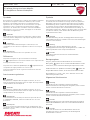
Kit installation
Caution
Check that all components are clean and in perfect condition
before installation.
Adopt any precaution necessary to avoid damages to any part of
the motorcycle you are working on.
Notes
To better understand how to install the kit, only the side stand unit
will be represented.
Pre-assemble no. 4 special nuts (5) on lower plate (1) and fix the
spacer plate (2) on the upper side of the plate (1) .
Notes
The special nuts (5) must be positioned with the collar (5A) facing
the lower plate, as shown in the figure (X).
Drive the pre-assembled plates fully home in the lower side of the
base (A1) of the stand (A).
From the upper side, position first the lower closing plate (3) and
then the upper closing plate (4), as shown in the figure.
Start no. 3 screws (6) and screw (7).
Tighten no. 3 screws (6) and screw (7) to the specified torque.
3
ISTR 661 / 00
3
6
4
6
7
6
1
2
A
A1
5
5
5
5A12
X
5 Nm ± 10%
5 Nm ± 10%

NOTAS / NOTES
1 P/N 商品名
2 P/N 商品名
3 P/N 商品名
4 P/N 商品名
5 P/N 商品名
ご注文商品
レース専用部品 ご注文書
DUCATI PERFORMANCE
accessories
モデル名
ご注文日
販売日 年 月 日
1.
上記
ご
記入
の
上
、
弊社
アフターセールス
部
まで
FAX
してください
。
FAX
:
03
-
6692
-
1317
お客様ご記入欄
私は上記レース専用部品を下記車両に装着し、サーキット走行のみに
利用し、一般公道には利用しません。
販売店署名
販売店様へお願い
車台番号 ZDM
お客様署名
ドゥカティ正規ネットワーク店記入欄
お客様に上記レース専用部品を販売し、レース専用部品のご利用方法を
説明いたしました。
1.
上記
ご
記入
の
上
、
弊社
アフターセールス
部
まで
FAX
してください
。
FAX
:
03
-
6692
-
1317
2.
取
り
付
け
車両
1
台
に
1
枚
でご
使用
ください
。
ISTR 661 / 00

シンボル
素早くかつ合理的に読み進めることができるように、本マニュア
ルではいくつかのシンボルを導入し、最大限の注意を払う必要が
ある状況や、推奨事項、または一般情報を明確にしてあります。
技術的概念や安全に関する警告を繰り返し記載する必要がないよ
うに機能しているので、各シンボルの意味に十分注意してくださ
い。シンボルは、実際上の“覚え書き” であると考えてくださ
い。シンボルなどの意味がわからなくなったり疑問に思う場合
は、必ずこのページで調べるようにしてください。
注記
この説明書に従わずに使用すると危険な状況を招き、重大なけ
が、あるいは死をももたらす原因となることがあります。
重要
この説明書に従わずに使用すると、車体及び/ 又はその部品に損
害を招く可能性があります
参考
操作中の内容に関する有用な情報を掲載しています。
参照
灰色で表示する部品、および参照番号 (Es.
1
) で表示する部品
は、キットに付属する取り付け部品および組み立て部品を示しま
す。
参照アルファベット (Es.
A
) で表示する部品は、車両に付属す
るオリジナル部品を示します。
すべての右及び左の指示は車体の進行方向を向いたものです。
一般警告事項
警告
以下のページに記載されている作業が規定通りに実施されない
と、ライダーの安全性を脅かすおそれがあります。
警告
以下のページに記載されている作業が規定通りに実施されない
と、ライダーの安全性を脅かすおそれがあります。
参考
キットの取り付けに必要な資料:お手持ちの車両モデルに対応す
るワークショップマニュアル 。
参考
キットの部品を交換する必要がある場合は、添付のスペアパーツ
表を参照してください。
Símbolos
Para una lectura rápida y racional se han empleado símbolos que
evidencian situaciones de máxima atención, consejos prácticos o
simples informaciones. Prestar mucha atención al significado de
los símbolos porque su función consiste en omitir la repetición de
conceptos técnicos o advertencias de seguridad. Los símbolos
deben considerarse como verdaderos “apuntes”. Consultar esta
página cada vez que se tengan dudas sobre su significado.
Atención
El incumplimiento de las instrucciones indicadas puede crear
una situación de peligro y ocasionar graves lesiones e incluso la
muerte.
Importante
Indica la posibilidad de provocar un daño al vehículo y/o a sus
componentes si no se siguen las instrucciones indicadas.
Notas
Suministra útiles informaciones sobre la operación en curso.
Referencias
Las partes resaltadas en gris y la referencia numérica
(Por ej.
1
) representan el accesorio que se debe instalar y los
eventuales componentes de montaje suministrados en el kit.
Las partes con referencia alfabética (Por ej.
A
) representan los
componentes originales presentes en la motocicleta.
Todas las indicaciones derecha o izquierda se refieren al sentido de
marcha de la motocicleta.
Advertencias generales
Atención
Las operaciones descritas en las siguientes páginas deben
realizarse correctamente para no perjudicar la seguridad del piloto.
Atención
Las operaciones descritas en las siguientes páginas deben
realizarse correctamente para no perjudicar la seguridad del
piloto.
Notas
La documentación necesaria para realizar el montaje del Kit es
el: MANUAL DE TALLER, relativo al modelo de moto en vuestro
poder.
Notas
Si fuera necesario sustituir un componente del kit, consultar la
tabla de recambios adjunta.
Kit placa ampliación base caballete
サイドスタンドエンドプレートキット
1
Multistrada 1200 ISTR - 661 / 00 97380331A

Pos. Descripciòn
説明
1 Placa inferior
ロアプレート
2 Placa separador
スペーサープレート
3 Placa de cierre inferior
ロアクロージングプレート
4 Placa de cierre superior
アッパークロージングプレート
5 Tuerca especial
専用ナット
6 Tornillo especial TBEI M5x12
スクリュー TBEI M5x12
7 Tornillo TBEI M5x10
スクリュー TBEI M5X10
2
ISTR 661 / 00
4
5
6
67
1
2
3
5

キット部品の取り付け
重要
取り付け前にすべての部品に汚れがなく、完璧な状態であること
を確認します。作業する部品の外側表面を傷つけないために、必
要な予防措置を取ってください
参考
キットの取り付けを分かりやすくするために、サイドスタンドユ
ニットだけを表示しています。
4 個の専用ナット (5) をロアプレート (1) に仮取り付けし、プ
レート (1) の上部にスペーサープレート (2) を取り付けます。
参考
図 (X) のように、専用ナット (5) はカラー (5A) がロアプレー
トの方に向くようにする必要があります。
仮取り付けしたプレートをスタンド (A) エンド (A1) の下部に奥
まで配置します。
図のように上側から、まずロアクロージングプレート (3) を配置
し、次にアッパークロージングプレート (4) を配置します。
3 本のスクリュー (6) およびスクリュー (7) を差し込みます。
3 本のスクリュー (6) およびスクリュー (7) を規定のトルクで
締め付けます。
Montaje componentes kit
Importante
Controlar, antes del montaje, que todos los componentes se
encuentren limpios y en perfecto estado.
Adoptar todas las precauciones necesarias para evitar daños en la
superficie exterior de los componentes donde se debe operar.
Notas
Para comprender mejor el montaje del kit, se representa sólo el
grupo caballete lateral.
Pre-montar las 4 tuercas especiales (5) en la placa inferior (1) y
montar la placa separador (2) en la parte superior de la placa (1).
Notas
Las tuercas especiales (5) deben orientarse con el collar (5A)
dirigido hacia la placa inferior, como ilustra la figura (X).
Colocar las placas recién pre-montadas en la parte inferior de la
base (A1) del caballete (A) hasta el tope.
Desde el lado superior, colocar primero la placa de cierre inferior (3)
y después la superior (4), como ilustra la figura.
Introducir los 3 tornillos (6) y el tornillo (7).
Ajustar los 3 tornillos (6) y el tornillo (7) al par de apriete indicado.
3
ISTR 661 / 00
3
6
4
6
7
6
1
2
A
A1
5
5
5
5A12
X
5 Nm ± 10%
5 Nm ± 10%

NOTAS / 参考
1 P/N 商品名
2 P/N 商品名
3 P/N 商品名
4 P/N 商品名
5 P/N 商品名
ご注文商品
レース専用部品 ご注文書
DUCATI PERFORMANCE
accessories
モデル名
ご注文日
販売日 年 月 日
1.
上記
ご
記入
の
上
、
弊社
アフターセールス
部
まで
FAX
してください
。
FAX
:
03
-
6692
-
1317
お客様ご記入欄
私は上記レース専用部品を下記車両に装着し、サーキット走行のみに
利用し、一般公道には利用しません。
販売店署名
販売店様へお願い
車台番号 ZDM
お客様署名
ドゥカティ正規ネットワーク店記入欄
お客様に上記レース専用部品を販売し、レース専用部品のご利用方法を
説明いたしました。
1.
上記
ご
記入
の
上
、
弊社
アフターセールス
部
まで
FAX
してください
。
FAX
:
03
-
6692
-
1317
2.
取
り
付
け
車両
1
台
に
1
枚
でご
使用
ください
。
ISTR 661 / 00

1 P/N 商品名
2 P/N 商品名
3 P/N 商品名
4 P/N 商品名
5 P/N 商品名
ご注文商品
レース専用部品 ご注文書
DUCATI PERFORMANCE
accessories
モデル名
ご注文日
販売日 年 月 日
1.
上記
ご
記入
の
上
、
弊社
アフターセールス
部
まで
FAX
してください
。
FAX
:
03
-
6692
-
1317
お客様ご記入欄
私は上記レース専用部品を下記車両に装着し、サーキット走行のみに
利用し、一般公道には利用しません。
販売店署名
販売店様へお願い
車台番号 ZDM
お客様署名
ドゥカティ正規ネットワーク店記入欄
お客様に上記レース専用部品を販売し、レース専用部品のご利用方法を
説明いたしました。
1.
上記
ご
記入
の
上
、
弊社
アフターセールス
部
まで
FAX
してください
。
FAX
:
03
-
6692
-
1317
2.
取
り
付
け
車両
1
台
に
1
枚
でご
使用
ください
。

4
5
6
67
1
2
3
5
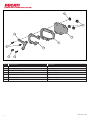
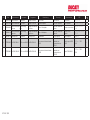
Multistrada 1200 ISTR - 661 / 00 97380331A
Kit piastra allargamento base cavalletto / Stand extension plate kit / Kit plaque d’extension base béquille / Kit vergrößerte Seitenstän-
derplatte / Conjunto de placa de alargamento base do descanso / Kit placa ampliación base caballete / サイドスタンドエンドプレー
トキット

Pos. Cod. Denominazione Description Designation Bezeichnung Descrição Denominacion
説明
Q.ty
1 97310781A Piastra inferiore Lower plate Plaque inférieure Untere Platte Placa inferior Placa inferior
ロアプレート
1
2 97310791A Piastra distanziale Spacer plate Plaque entretoise Distanzstückplatte Placa do espaçador Placa separador
スペーサープレート
1
3 97310801A
Piastra di chiusura
inferiore
Lower closing
plate
Plaque de fermeture
inférieure
Untere Schließplatte
Placa de fechamento
inferior
Placa de cierre inferior
ロアクロージングプ
レート
1
4 97310811A
Piastra di chiusura
superiore
Upper closing
plate
Plaque de fermeture
supérieure
Obere Schließplatte
Placa de fechamento
superior
Placa de cierre
superior
アッパークロージング
プレート
1
5 97610421A Dado speciale Special nut Écrou spécial Spezialmutter Porca especial Tuerca especial
専用ナット
4
6 77550329E Vite TBEI M5x12 TBEI screw M5x12 Vis TBHC M5x12
Linseninnensechskantschraube
M5x12
Parafuso de cabeça
abaulada com
sextavado interno
M5x12
Tornillo especial TBEI
M5x12
スクリュー TBEI
M5x12
3
7 77550389E Vite TBEI M5x10 TBEI screw M5x10 Vis TBHC M5x10
Linseninnensechskantschraube
M5x10
Parafuso de cabeça
abaulada com
sextavado interno
M5x10
Tornillo TBEI M5x10
スクリュー TBEI
M5X10
1
ISTR 661 / 00
-
 1
1
-
 2
2
-
 3
3
-
 4
4
-
 5
5
-
 6
6
-
 7
7
-
 8
8
-
 9
9
-
 10
10
-
 11
11
-
 12
12
-
 13
13
-
 14
14
-
 15
15
-
 16
16
-
 17
17
-
 18
18
-
 19
19


em outras línguas
- español: Ducati 97380331A
- français: Ducati 97380331A
- italiano: Ducati 97380331A
- English: Ducati 97380331A
- Deutsch: Ducati 97380331A
- 日本語: Ducati 97380331A
Artigos relacionados
-
Ducati 96981061A Installation Instructions Manual
-
-
-
-
-
-
-
-
-