
Symbols
To allow quick and easy consultation, this manual uses graphic
symbols to highlight situations in which maximum care is required,
as well as practical advice or information.
Pay attention to the meaning of the symbols since they serve to
avoid repeating technical concepts or safety warnings throughout
the text. The symbols should therefore be seen as real reminders.
Please refer to this page whenever in doubt as to their meaning.
Warning
Failure to follow these instructions might give raise to a dangerous
situation and provoke severe personal injuries or even death.
Caution
Failure to follow these instructions might cause damages to the
vehicle and/or its components.
Notes
Useful information on the procedure being described.
References
Parts highlighted in grey and with a numeric reference
(Example
1
) are the accessory to be installed and any assembly
components supplied with the kit.
Parts with an alphabetic reference (Example
A
) are the original
components fitted on the vehicle.
Any right- or left-hand indication refers to the vehicle direction of
travel.
General notes
Warning
Carefully perform the operations on the following pages since they
might negatively affect rider safety.
Warning
Carefully perform the operations on the following pages since they
might negatively affect rider safety.
Notes
The following documents are necessary for assembling the Kit:
WORKSHOP MANUAL of your bike model.
Notes
Should it be necessary to change any kit parts, please refer to the
attached spare part table.
Simbologia
Per una lettura rapida e razionale sono stati impiegati simboli che
evidenziano situazioni di massima attenzione, consigli pratici o
semplici informazioni.
Prestare molta attenzione al significato dei simboli, in quanto la
loro funzione è quella di non dovere ripetere concetti tecnici o
avvertenze di sicurezza. Sono da considerare, quindi, dei veri e
propri “promemoria”.
Consultare questa pagina ogni volta che sorgeranno dubbi sul loro
significato.
Attenzione
La non osservanza delle istruzioni riportate può creare una
situazione di pericolo e causare gravi lesioni personali e anche la
morte.
Importante
Indica la possibilità di arrecare danno al veicolo e/o ai suoi
componenti se le istruzioni riportate non vengono eseguite.
Note
Fornisce utili informazioni sull’operazione in corso.
Riferimenti
I particolari evidenziati in grigio e riferimento numerico (Es.
1
)
rappresentano l’accessorio da installare e gli eventuali componenti
di montaggio forniti a kit.
I particolari con riferimento alfabetico (Es.
A
) rappresentano i
componenti originali presenti sul motoveicolo.
Tutte le indicazioni destro o sinistro si riferiscono al senso di marcia
del motociclo.
Avvertenze generali
Attenzione
Le operazioni riportate nelle pagine seguenti devono essere
eseguite da un tecnico specializzato o da un’officina autorizzata
DUCATI.
Attenzione
Le operazioni riportate nelle pagine seguenti se non eseguite a
regola d’arte possono pregiudicare la sicurezza del pilota.
Note
Documentazione necessaria per eseguire il montaggio del Kit
è il MANUALE OFFICINA, relativo al modello di moto in vostro
possesso.
Note
Nel caso fosse necessaria la sostituzione di un componente del kit
consultare la tavola ricambi allegata.
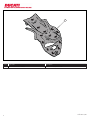
Kit portatarga in carbonio
Carbon number plate holder kit
1
Multistrada 1200 ISTR - 681 / 00 96980731A

Pos. Denominazione Description
1 Portatarga in carbonio Carbon number plate holder
2
ISTR 681 / 00
1

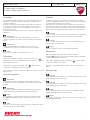
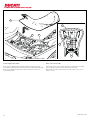
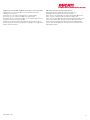
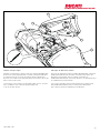
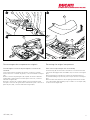
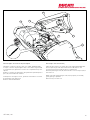
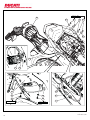
Removing the original components
Rider seat and passenger seat disassembly
Insert the key (A) into the seat lock and turn it clockwise until the
seat catch disengages with an audible click, as shown in the figure
(X1).
Remove passenger seat (A1) from the front retainer pushing it
forward and lifting it up until fully removed, as shown in the figure
(X2).
Remove rider seat (A2) from vehicle pulling it backward to slide it
out of the guides (A3) and lifting it up to slide it out of the pin (A4),
as shown in the figure (X3).
Smontaggio componenti originali
Smontaggio sella passeggero e sella pilota
Inserire la chiave (A) nella serratura sella e ruotarla in senso orario
fino a sentire lo scatto del gancio, come indicato in figura (X1).
Sfilare la sella passeggero (A1) dal fermo anteriore spingendola in
avanti e sollevarla fino ad estrarla, come indicato in figura (X2).
Rimuovere la sella conducente (A2) dal veicolo tirandola all’indietro
per sfilarla dalle guide (A3) e sollevandola per sfilarla dal perno (A4),
come indicato in figura (X3).
3
ISTR 681 / 00
OPEN
X1
X2
X3
A4
A2
A3
A
A1

4
ISTR 681 / 00
B5
B4
B1
C
B5
B
B
B2B2B3 B3
B3
B4

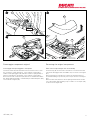
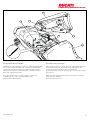
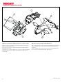
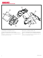
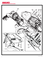
Removing the number plate holder unit
Disconnect the rear light cable connector (B1) from rear light
wiring branch (C).
Loosen no. 4 upper screws (B2) with washers (B3).
Loosen no. 2 lower screws (B4) with bushings (B5).
Collect no. 4 upper screws (B2), no. 4 washers (B3), no. 2 lower
screws (B4) and no. 2 bushings (B5).
Remove the number plate holder unit (B) paying attention not to
damage the wiring and not to ruin the number plate holder.
Smontaggio gruppo portatarga
Scollegare il connettore cavo luci posteriori (B1) dal ramo cablaggio
luci posteriori (C).
Svitare le n.4 viti superiori (B2) con rondelle (B3).
Svitare le n.2 viti inferiori (B4) con boccole (B5).
Recuperare le n.4 viti superiori (B2), le n.4 rondelle (B3), le n.2 viti
inferiori (B4) e le n.2 boccole (B5).
Rimuovere il gruppo portatarga (B) prestando attenzione a non
danneggiare il cablaggio e a non rovinare il portatarga.
5
ISTR 681 / 00

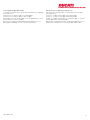
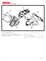
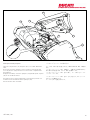
Removing the number plate holder cover
Remove the number plate (F) from number plate holder plate (E).
Loosen no. 3 screws (E1) and remove number plate holder plate
(E).
Loosen no. 4 screws (D1) and remove number plate holder cover
(D) from lower number plate holder (B).
Smontaggio coperchio portatarga
Rimuovere la targa (F) dal piatto portatarga (E).
Svitare le n.3 viti (E1) e rimuovere il piatto portatarga (E).
Svitare le n.4 viti (D1) e rimuovere il coperchio portatarga (D) dal
portatarga inferiore (B).
6
ISTR 681 / 00
F
D
E
D1
D1
B
E1

Remove no. 2 clips (D2), no. 4 clips (D3) and no. 2 rubber blocks
(D4) from number plate holder cover (D).
Collect all removed components.
Rimuovere le n.2 clip (D2), le n.4 clip (D3) e i n.2 tamponi in
gomma (D4) dal coperchio portatarga (D).
Recuperare tutti i componenti rimossi.
7
ISTR 681 / 00
D4
D4
D2
D3
D3
D

8
ISTR 681 / 00
D3
1
D2
D4
D3
D4
D3
F
1
E1
6 Nm ± 10%
E
D1
D1
3 Nm ± 10%
3 Nm ± 10%
B

Kit installation
Caution
Check that all components are clean and in perfect condition
before installation.
Adopt any precaution necessary to avoid damages to any part of
the motorcycle you are working on.
Warning
When fitting carbon parts, take special care when tightening
fastening screws.
Tighten fasteners without forcing too much to prevent carbon parts
from being damaged.
Number plate holder cover pre-assembly
Fit no. 4 original clips (D3) and no. 2 original clips (D2) in the
indicated areas of the number plate holder cover (1), aiming them
as shown in the figure.
Fit no. 2 original rubber blocks (D4) on the brackets of the number
plate holder cover (1), inserting them from the side shown.
Refitting the number plate holder cover
Match the number plate holder cover (1) to the lower number plate
holder (B) and start no. 4 original screws (D1).
Warning
During the operation, make sure that cables are not squeezed
between number plate holder cover (1) and lower number plate
holder (B).
Tighten the no. 4 original screws (D1) to the specified torque.
Position number plate holder plate (E) on number plate holder
cover and start no. 3 original screws (E1).
Tighten the no. 3 original screws (E1) to the specified torque.
Refit number plate (F) on number plate holder plate (E).
Montaggio componenti kit
Importante
Verificare, prima del montaggio, che tutti i componenti risultino
puliti e in perfetto stato.
Adottare tutte le precauzioni necessarie per evitare di danneggiare
qualsiasi parte nella quale ci si trova ad operare.
Attenzione
Durante il montaggio di componenti in carbonio porre particolare
attenzione al serraggio delle viti di fissaggio.
Serrare gli elementi di fissaggio senza forzare eccessivamente per
evitare che il carbonio si danneggi.
Preassemblaggio coperchio portatarga
Inserire le n.4 clips originali (D3) e le n.2 clips originali (D2)
nelle zone indicate del coperchio portatarga (1), rispettando
l’orientamento mostrato in figura.
Montare i n.2 tamponi in gomma originali (D4) sulle staffe del
coperchio portatarga (1), inserendoli dal lato indicato.
Montaggio coperchio portatarga
Accoppiare il coperchio portatarga (1) al portatarga inferiore (B) e
impuntare le n.4 viti originali (D1).
Attenzione
Durante l’operazione, assicurarsi che i cavi non rimangano
schiacciati tra il coperchio portatarga (1) e il portatarga inferiore (B).
Serrare le n.4 viti originali (D1) alla coppia indicata.
Posizionare il piatto portatarga (E) sul coperchio portatarga e
impuntare le n.3 viti originali (E1).
Serrare le n.3 viti originali (E1) alla coppia indicata.
Rimontare la targa (F) sul piatto portatarga (E).
9
ISTR 681 / 00

10
ISTR 681 / 00
B5
B4
B1
B6
C
B
B6
B2B2B3
G1 B6
B3
B3
6 Nm ± 10%
6 Nm ± 10%
B5
B
B4
6 Nm ± 10%

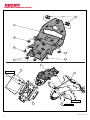
Fitting the number plate holder unit
Insert the rear light wiring cable (B6) in the opening (G1) on the
electrical components compartment, as shown in the figure.
Connect the rear light cable connector (B1) to rear light wiring
branch (C).
Position number plate holder unit (B) on grab handle and start no. 4
upper original screws (B2) with original washers (B3).
Start no. 2 lower original screws (B4) with relevant original
bushings (B5).
Warning
During the operation, make sure that rear light wiring cable (B6) is
not squeezed between grab handle and number plate holder unit
(B).
Tighten no. 4 upper original screws (B2) and no. 2 lower original
screws (B4) to the specified torque.
Montaggio gruppo portatarga
Inserire il cavo cablaggio luci posteriori (B6) nell’apertura (G1)
presente sulla vasca componenti elettrici, come mostrato nel
riquadro.
Collegare il connettore cavo luci posteriori (B1) dal ramo cablaggio
luci posteriori (C).
Posizionare il gruppo portatarga (B) sul maniglione e impuntare le
n.4 viti superiore originali (B2) con rondelle originali (B3).
Impuntare le n.2 viti inferiori originali (B4) con relative boccole
originali (B5).
Attenzione
Durante l’operazione, assicurarsi che il cavo cablaggio luci
posteriori (B6) non rimanga schiacciato tra il maniglione e il gruppo
portatarga (B).
Serrare le n.4 viti superiori originali (B2) e le n.2 viti inferiori originali
(B4) alla coppia indicata.
11
ISTR 681 / 00

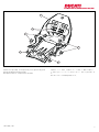
Rider seat reassembly
Position the front side of rider seat (A), provided with slots (A6),
into guides (A3) and insert pin (A4) into its seat (A5).
Press rider seat (A) towards the front side of the motorcycle in
order to lock it.
Rimontaggio sella pilota
Posizionare la parte anteriore della sella pilota (A), provvista di
asole (A6), nelle guide (A3) ed inserire il perno (A4) nella sede (A5).
Premere la sella pilota (A) verso l’anteriore del motoveicolo in
modo da bloccarla.
12
ISTR 681 / 00
A2
A
A6
A5
A3 A4

Passenger seat reassembly
Lubricate the seat (T1) of the pin (A7) with SHELL RETINAX HD2.
Position passenger seat (A1) and insert the tab (A8) into the
housing (T2) present inside the glove compartment.
Push the passenger seat (A1) downwards to secure the pin (A7) in
the seat lock.
Make sure that the passenger seat (A1) is properly secured by
gently pulling it upwards.
Remove key from the lock.
Rimontaggio sella passeggero
Lubrificare la sede (T1) del perno (A7) con SHELL RETINAX HD2.
Posizionare la sella passeggero (A1) e inserire la linguetta (A8)
nell’alloggio (T2) presente all’interno della vasca portaoggetti.
Spingere verso il basso la sella passeggero (A1) per bloccare il
perno (A7) nella serratura sella.
Accertarsi dell’avvenuto e corretto aggancio, tirando con
moderazione verso l’alto la sella passeggero (A1).
Sfilare la chiave dalla serratura.
13
ISTR 681 / 00
A1
T1
T2
A7
A
A8

NOTE / NOTES
1 P/N 商品名
2 P/N 商品名
3 P/N 商品名
4 P/N 商品名
5 P/N 商品名
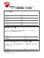
ご注文商品
レース専用部品 ご注文書
DUCATI PERFORMANCE
accessories
モデル名
ご注文日
販売日 年 月 日
1.
上記
ご
記入
の
上
、
弊社
アフターセールス
部
まで
FAX
してください
。
FAX
:
03
-
6692
-
1317
お客様ご記入欄
私は上記レース専用部品を下記車両に装着し、サーキット走行のみに
利用し、一般公道には利用しません。
販売店署名
販売店様へお願い
車台番号 ZDM
お客様署名
ドゥカティ正規ネットワーク店記入欄
お客様に上記レース専用部品を販売し、レース専用部品のご利用方法を
説明いたしました。
1.
上記
ご
記入
の
上
、
弊社
アフターセールス
部
まで
FAX
してください
。
FAX
:
03
-
6692
-
1317
2.
取
り
付
け
車両
1
台
に
1
枚
でご
使用
ください
。
ISTR 681 / 00

Symbole
Zum schnellen und übersichtlichen Lesen werden Symbole
verwendet, die außerordentlich wichtige Situationen, praktische
Ratschläge oder auch nur einfache Informationen hervorheben.
Der Bedeutung dieser Symbole ist besondere Aufmerksamkeit
zu schenken, da sich hierdurch das ständige Wiederholen von
technischen Konzepten oder Sicherheitshinweisen erübrigt. Sie
stellen daher regelrechte „Merker“ dar. Diese Seite ist immer dann
zur Hand zu nehmen, wenn Zweifel über die Bedeutung eines
Symbols bestehen sollten.
Achtung
Eine Nichtbeachtung der hier wiedergegebenen Anweisungen
kann Gefahrensituationen schaffen und zu schweren Verletzungen
und auch zum Tod führen.
Wichtig
Weist darauf hin, dass bei Nichteinhaltung der hier
wiedergegebenen Anweisungen die Möglichkeit für Schäden am
Fahrzeug und/oder seiner Komponenten besteht.
Hinweis
Übermittelt nützliche Informationen zum betreffenden
Arbeitseingriff.
Bezugsangaben
Die grau gekennzeichneten Bestandteile mit numerischem
Bezug (Bsp.
1
) geben das zu installierende Bestandteil und die
eventuellen, im Kit enthaltenen Montagekomponenten wieder.
Die Bestandteile mit alphabetischem Bezug (Bsp.
A
) geben die
Original-Bestandteile wieder, die am Motorrad verbaut wurden.
Alle Angaben wie „rechts” oder „links” beziehen sich auf die
Fahrtrichtung des Motorrads.
Allgemeine Warnhinweise
Achtung
Werden die auf den folgenden Seiten beschriebenen
Arbeitsmaßnahmen nicht fachgerecht ausgeführt, kann sich dies
auf die Sicherheit des Fahrers auswirken.
Achtung
Werden die auf den folgenden Seiten beschriebenen
Arbeitsmaßnahmen nicht fachgerecht ausgeführt, kann sich dies
auf die Sicherheit des Fahrers auswirken.
Hinweis
Für die Montage des Kits sind folgende Unterlagen erforderlich:
WERKSTATTHANDBUCH, des sich in Ihrem Besitz befindlichen
Motorrads.
Hinweis
Sollte sich der Austausch eines Bestandteils des Kits als
erforderlich erweisen, ist dazu Bezug auf die beiliegende
Ersatzteiltafel zu nehmen.
Symboles
Pour faciliter la consultation de ce manuel, des symboles signalent
des situations exigeant le maximum d'attention, des conseils
pratiques ou de simples informations. Lire attentivement la
signification de ces symboles car ils renvoient à des concepts
techniques ou des consignes de sécurité de la plus grande
importance. Ils doivent être considérés comme de véritables «
aide-mémoire ». Toujours consulter cette page en cas de doute
concernant leur signification.
Attention
La non-observance des instructions reportées ci-dessous peut
créer une situation dangereuse et provoquer de graves lésions
personnelles voire la mort.
Important
Indique la possibilité d'endommager le véhicule et/ou ses
composants si les instructions reportées ci-dessous ne sont pas
suivies.
Remarques
Fournit des informations utiles sur l'opération en cours.
Références
Les pièces surlignées en gris et la référence numérique
(Ex.
1
) représentent l'accessoire à installer et les composants de
montage éventuels fournis en kit.
Les pièces avec référence alphabétique (Ex.
A
) représentent les
composants d'origine présents sur le motocycle.
Toutes les indications droite ou gauche se réfèrent au sens de
marche la moto.
Avertissements généraux
Attention
Les opérations indiquées dans les pages suivantes, au cas où
elles ne seraient pas effectuées selon les règles de l'art pourraient
compromettre la sécurité du pilote.
Attention
Les opérations indiquées dans les pages suivantes, au cas où
elles ne seraient pas effectuées selon les règles de l'art pourraient
compromettre la sécurité du pilote.
Remarques
La documentation nécessaire pour effectuer la pose du Kit est
le : MANUEL D'ATELIER, relatif au modèle de moto en votre
possession.
Remarques
Au cas où il serait nécessaire d'effectuer le remplacement d'un
composant du kit, il faudra consulter la planche relative aux pièces
détachées ci-jointe.
Kit support de plaque d’immatriculation en carbone
Kit Kennzeichenhalter aus Kohlefaser
1
Multistrada 1200 ISTR - 681 / 00 96980731A

Pos. Designation Bezeichnung
1 Support de plaque d'immatriculation en carbone Kennzeichenhalter aus Kohlefaser
2
ISTR 681 / 00
1

Ausbau der Original-Bestandteile
Abnahme von Beifahrer- und Fahrersitzbank
Den Schlüssel (A) in das Sitzbankschloss einstecken und so lange
im Uhrzeigersinn drehen, bis das Lösen der Verriegelung zu hören
ist; siehe Abbildung (X1).
Die Beifahrersitzbank (A1) von der vorderen Befestigung lösen,
dabei nach vorne drücken und so weit anheben, bis sie sich
abziehen lässt; siehe Abbildung (X2).
Die Fahrersitzbank (A2) vom Fahrzeug entfernen, sie dazu nach
hinten ziehen, um sie von den Führungen (A3) zu lösen, dann
anheben, um sie vom Bolzen (A4) abzuziehen; siehe Abbildung
(X3).
Dépose composants d'origine
Dépose selle passager et selle pilote
Insérer la clé (A) dans la serrure de la selle et la tourner dans le
sens des aiguilles d'une montre jusqu'à entendre le déclic du
crochet, comme indiqué dans la figure (X1).
Sortir la selle passager (A1) de l'arrêtoir avant en la poussant en
avant et la soulever jusqu'à l'extraire, comme indiqué dans la figure
(X2).
Déposer la selle pilote (A2) du motocycle en la tirant en arrière
pour la sortir des guides (A3) et la soulever pour la sortir du pivot
(A4), comme indiqué dans la figure (X3).
3
ISTR 681 / 00
OPEN
X1
X2
X3
A4
A2
A3
A
A1

4
ISTR 681 / 00
B5
B4
B1
C
B5
B
B
B2B2B3 B3
B3
B4

Abnahme der Kennzeichenhaltereinheit
Den Verbinder des Kabels der Rücklichter (B1) vom
Verkabelungszweig der Rücklichter (C) trennen.
Die 4 oberen Schrauben (B2) mit Unterlegscheiben (B3) lösen.
Die 2 unteren Schrauben (B4) mit Buchsen (B5) lösen.
Die 4 oberen Schrauben (B2), die 4 Unterlegscheiben (B3), die 2
unteren Schrauben (B4) und die 2 Buchsen (B5) aufnehmen.
Die Kennzeichenhaltereinheit (B) entfernen und dabei darauf
achten, dass die Verkabelung und der Kennzeichenhalter nicht
beschädigt werden.
Dépose de l'ensemble support de plaque d'immatriculation
Débrancher le connecteur câble feux arrière (B1) du brin de
câblage feux arrière (C).
Desserrer les 4 vis supérieures (B2) avec rondelles (B3).
Desserrer les 2 vis inférieures (B4) avec bagues (B5).
Récupérer les 4 vis supérieures (B2), les 4 rondelles (B3), les 2 vis
inférieures (B4) et les 2 bagues (B5).
Déposer l'ensemble support de plaque d'immatriculation (B) en
prenant garde de ne pas endommager le câblage et le support de
plaque d'immatriculation.
5
ISTR 681 / 00

Abnahme der Kennzeichenhalterabdeckung
Das Kennzeichen (F) von der Kennzeichenhalterplatte (E) entfernen.
Die 3 Schrauben (E1) lösen und die Kennzeichenhalterplatte (E)
entfernen.
Die 4 Schrauben (D1) lösen und die Kennzeichenhalterabdeckung
(D) vom unteren Kennzeichenhalter (B) entfernen.
Dépose du couvercle support de plaque d'immatriculation
Déposer la plaque d'immatriculation (F) de la platine de support
plaque d'immatriculation (E).
Desserrer les 3 vis (E1) et déposer la platine de support plaque
d'immatriculation (E).
Desserrer les 4 vis (D1) et déposer le couvercle support de plaque
d'immatriculation (D) du support de plaque d'immatriculation
inférieur (B).
6
ISTR 681 / 00
F
D
E
D1
D1
B
E1
A página está carregando...
A página está carregando...
A página está carregando...
A página está carregando...
A página está carregando...
A página está carregando...
A página está carregando...
A página está carregando...
A página está carregando...
A página está carregando...
A página está carregando...
A página está carregando...
A página está carregando...
A página está carregando...
A página está carregando...
A página está carregando...
A página está carregando...
A página está carregando...
A página está carregando...
A página está carregando...
A página está carregando...
A página está carregando...
A página está carregando...
A página está carregando...
A página está carregando...
A página está carregando...
A página está carregando...
A página está carregando...
A página está carregando...
A página está carregando...
A página está carregando...
A página está carregando...
A página está carregando...
A página está carregando...
A página está carregando...
A página está carregando...
A página está carregando...
-
 1
1
-
 2
2
-
 3
3
-
 4
4
-
 5
5
-
 6
6
-
 7
7
-
 8
8
-
 9
9
-
 10
10
-
 11
11
-
 12
12
-
 13
13
-
 14
14
-
 15
15
-
 16
16
-
 17
17
-
 18
18
-
 19
19
-
 20
20
-
 21
21
-
 22
22
-
 23
23
-
 24
24
-
 25
25
-
 26
26
-
 27
27
-
 28
28
-
 29
29
-
 30
30
-
 31
31
-
 32
32
-
 33
33
-
 34
34
-
 35
35
-
 36
36
-
 37
37
-
 38
38
-
 39
39
-
 40
40
-
 41
41
-
 42
42
-
 43
43
-
 44
44
-
 45
45
-
 46
46
-
 47
47
-
 48
48
-
 49
49
-
 50
50
-
 51
51
-
 52
52
-
 53
53
-
 54
54
-
 55
55
-
 56
56
-
 57
57


em outras línguas
- español: Ducati 96980731A Manual de usuario
- français: Ducati 96980731A Manuel utilisateur
- italiano: Ducati 96980731A Manuale utente
- English: Ducati 96980731A User manual
- Deutsch: Ducati 96980731A Benutzerhandbuch
- 日本語: Ducati 96980731A ユーザーマニュアル
Artigos relacionados
-
Ducati 96380031A Instructions Manual
-
-
-
-
-
-
-
-
-