A página está carregando...

Modelli di riferimento: / Reference Ducati Motorcycles:
Cod. ISTR - 508 Pag. - Page 1/17ED./ED. 01
ISTR - 508 ED./ED. 01
I particolari evidenziati in grigio e riferimento numerico (Es. ) rappresentano l’accessorio da
installare e gli eventuali componenti di montaggio forniti a kit. I particolari con riferimento
alfabetico (Es. ) rappresentano i componenti originali presenti sul motoveicolo.
Per una lettura rapida e razionale sono stati impiegati simboli che evidenziano situazioni di
massima attenzione, consigli pratici o semplici informazioni.
Tutte le indicazioni destro o sinistro si riferiscono al senso di marcia del motociclo.
Parts highlighted in grey and with a numeric reference (Example ) are the accessory to be
installed and any assembly components supplied with the kit. Parts with an alphabetic reference
(Example ) are the original components fitted on the vehicle.
For easy and rational reading, this document uses graphic symbols for
highlighting situations in which maximum care is required, practical advice or simple information.
Any right- or left-hand indication refers to the vehicle direction of travel.
Attenzione / Warning
La non osservanza delle istruzioni riportate può creare una situazione di pericolo e causare
gravi lesioni personali e anche la morte. / Failure to follow these instructions might give raise to
a dangerous situation and provoke severe personal injuries or even death.
Importante / Caution
Indica la possibilità di arrecare danno al veicolo e/o ai suoi componenti se le istruzioni
riportate non vengono eseguite. / Failure to follow these instructions might cause damages to the
vehicle and/or its components.
Note / Note
Fornisce utili informazioni sull'operazione in corso. / Useful information on the procedure
being described.
2
A
2
A
Diavel
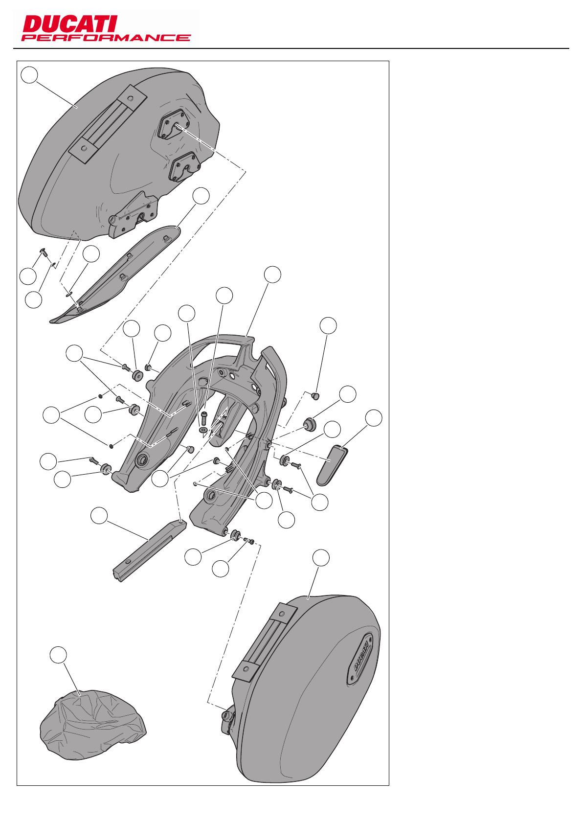
Kit valigie semirigide laterali / Semi-rigid side pannier kit - 96780011A
1 Telaietto supporto borse
2 Vite TBEI M8x45
3 Recuperatore di gioco
4Ghiera
5 Cablaggio posteriore sinistro
6 Cablaggio posteriore destro
7 Fanale posteriore
8 Indicatore posteriore destro
9 Indicatore posteriore sinistro
10 Dado autobloccante
11 Gommino
12 Rosetta
13 Distanziale
14 Vite TEF M5x22
15 Piastrino massa destro
16 Piastrino massa sinistro
17 Vite STEI M8x30
1 Pannier subframe
2 TBEI screw M8x45
3 Clearance adjuster
4Nut
5 LH rear wiring loom
6 RH rear wiring loom
7 Tail light
8 RH rear indicator
9 LH rear indicator
10 Self-locking nut
11 Rubber block
12 Washer
13 Spacer
14 TEF screw M5x22
15 RH ground plate
16 LH ground plate
17 STEI screw M8x30
16
9
2
5
8
12
17
3
17
10
11
13
15
7
13
11
10
12
14
3
4
2
4
1
6
14

Pag. - Page 2/17 Cod. ISTR - 508
ED./ED. 01
18 M8 hole plug
19 Outlet plug
20 Short pannier retainer
21 Rear sprocket fastener
22 Handle
23 Rear cat's eye
24 TCEIF screw M8x25
25 Flat washer
26 TSPEI screw M6x20
27 Socket cap screw M6x20
28 Long pannier retainer
29 RH side pannier
30 LH side pannier
31 Pannier heat shield
32 TBEIF screw M5x16 (q.ty 5)
33 Washer (q.ty 5)
34 Spacer (q.ty 5)
35 Waterproof cover (q.ty 2)
18
29
34
19
28
1
20
32
33
18
31
23
26
20
18
21
27
30
22
35
26
21
20
20
24
25
27
28
18 Tappo foro M8
19 Tappo per presa
20 Funghetto aggancio borse corto
21 Fissaggio a corona
22 Maniglia
23 Catadiottro posteriore
24 Vite TCEIF M8x25
25 Rosetta piana
26 Vite TSPEI M6x20
27 Vite TCEI M6x20
28 Funghetto aggancio borse lungo
29 Borsa destra
30 Borsa sinistra
31 Paracalore borsa
32 Vite TBEIF M5x16 (q.tà 5)
33 Rosetta (q.tà 5)
34 Distanziale (q.tà 5)
35 Sacca impermeabile (q.tà 2)

Pag. - Page 3/17Cod. ISTR - 508 ED./ED. 01
Note
Read the instructions on the first
page carefully before proceeding.
Warning
Have the kit installed by a trained
technician or at a DUCATI Authorized
Workshop.
Removing the original
components
Warning
Incorrect installation of this kit may
put the rider’s safety at risk.
Remove seat as specified in "Removing the
Seat".
Remove rear mudguard as specified in
"Removing rear mudguard".
Unscrew the six screws (B) and remove the
cover guard (A).
Loosen screw (E) and release keylock (F).
Unscrew the four screws (H) and remove
keylock unit (G) keeping washers (I).
Loosen screw (G1) and remove knob (G2),
spring (G3) and pin (G4) from keylock (G).
Fully remove rear grab handle (D) and lift to
free it from the retainer tooth (L1).
Disconnect connectors (P6) and (N6) from
rear tail lights (P) and (N).
Loosen screw (P4) with washer (P5) and
remove RH tail light (P) towards the back.
Remove spacers (P1), (P3) and rubber block
(P2) from glove compartment (L).
Loosen screw (N4) with washer (N5) and
remove LH tail light (N) towards the back.
Remove spacers (N1), (N3) and rubber block
(N2) from glove compartment (L).
Remove rubber blocks (M) from glove
compartment (L).
C
P
B
D
C
A
L
G
E
F
H
G1
G2
G3
G4
I
G1
P1
P6
L
M
P2 P3 P5 N4 N5
N3
N2
N1
N
M
N6
Note
Prima di iniziare l’operazione, leggere
attentamente le avvertenze riportate nella
prima pagina.
Attenzione
Le operazioni di seguito riportate
devono essere eseguite da un tecnico
specializzato o da un’officina autorizzata
DUCATI.
Smontaggio componenti
originali
Attenzione
Le operazioni di seguito riportate se
non eseguite a regola d’arte possono
pregiudicare la sicurezza del pilota.
Rimuovere la sella seguendo quanto
riportato al capitolo “Smontaggio sella”.
Rimuovere il parafango posteriore
seguendo quanto riportato al capitolo
"Smontaggio parafango posteriore".
Svitare le sei viti (B) e rimuovere il coperchio
(A).
Svitare le viti (E) e sganciare il blocco chiave
(F).
Svitare le quattro viti (H) e rimuovere il
gruppo blocchetto (G) recuperando le
rondelle (I).
Svitare la vite (G1) e smontare il pomello
(G2), la molla (G3) e il piolo (G4) dal
blocchetto (G).
Sfilare il maniglione posteriore (D) fino a
battuta e sollevare per svincolarlo dal
dentino di fermo (L1).
Scollegare i connettori (P6) e (N6) dei fanali
posteriori (P) e (N).
Svitare la vite (P4) con rondella (P5) e sfilare
verso la parte posteriore il fanale destro (P).
Rimuovere i distanziali (P1), (P3) e il
gommino (P2) dalla vasca portaoggetti (L).
Svitare la vite (N4) con rondella (N5) e sfilare
verso la parte posteriore il fanale sinistro
(N).
Rimuovere i distanziali (N1), (N3) e il
gommino (N2) dalla vasca portaoggetti (L).
Rimuovere i gommini (M) dalla vasca
portaoggetti (L).

Pag. - Page 4/17 Cod. ISTR - 508
ED./ED. 01
Kit installation
Caution
Check that all components are clean
and in perfect condition before installation.
Take adequate measures to avoid damaging
the internal components of the engine.
Pre-assembly of pannier subframe
Insert LH rear indicator (9) retaining nut (10)
in the seat on the LH side of pannier
subframe (1).
Insert LH rear indicator wiring (9A) in hole
(1A) going through the inner part of nut (10)
and bring turn indicator fully home on the
subframe.
Start nut (10) on turn indicator thread and
tighten it to a torque of 5±10% Nm.
Insert LH rear turn indicator wiring (9A)
through hole (1B).
Repeat the same procedure to assemble
RH rear turn indicator (8).
Remove protective film on rear side of LH
ground plate (16) and apply it on LH rear tail
light (7).
Remove protective film on rear side of RH
ground plate (15) and apply it on RH rear tail
light (7).
Fit grommets (11) in relative holes on
pannier subframe (1) and introduce spacers
(13) in grommets (11).
Insert wiring (7A) through hole (1B) on LH
pannier subframe (1) and bring tail light fully
home (7) with buffers (15) and (16) on
subframe.
Start screws (14) with washers (12) on
pannier subframe inner part securing tail
light (7).
Tighten screws (14) to a torque of 5±10%
Nm.
Grease clearance adjusters threads (3) and
nuts (4) using GADIUS S2 V220 AD2
grease, making sure not to apply grease on
the clearance adjusters surface (3A).
Screw clearance adjusters (3) to their
washers (4), until the sides with the flats are
at the same level, as shown in the figure (X).
Screw clearance adjusters (3) with washers
(4) up to the edge of frame bushes internal
surface, as shown in the figure (Y).
1
15
4
4
3
9
14
12
16
10
1A
1B
9A
8A
8
13
11
13
7
7A
1B
12
14
43
3
1
3A
Montaggio componenti kit
Importante
Verificare, prima del montaggio, che
tutti i componenti risultino puliti e in
perfetto stato.
Adottare tutte le precauzioni necessarie per
evitare di danneggiare qualsiasi parte nella
quale ci si trova ad operare.
Premontaggio telaietto supporto borse
Inserire il dado (10) di fissaggio indicatore
posteriore sinistro (9) nella sede ricavata sul
lato sinistro del telaietto supporto borse (1).
Inserire il cablaggio (9A) dell'indicatore
posteriore sinistro nel foro (1A) facendolo
passare all'interno del dado (10) e portare a
battuta l'indicatore di direzione sul telaietto.
Avvitare il dado (10) sul filetto dell'indicatore
di direzione e serrarlo alla coppia di
serraggio 5±10% Nm.
Inserire il cablaggio (9A) dell'indicatore
posteriore sinistro attraverso il foro (1B).
Ripetere la stessa operazione per il
montaggio dell'indicatore posteriore destro
(8).
Rimuovere la pellicola protettiva presente
sul lato posteriore del piastrino massa
sinistro (16) e applicarlo sul lato posteriore
sinistro del fanale posteriore (7).
Rimuovere la pellicola protettiva presente
sul lato posteriore del piastrino massa
destro (15) e applicarlo sul lato posteriore
destro del fanale posteriore (7).
Montare i gommini (11) nei relativi fori
ricavati sul telaietto supporto borse (1)e
inserire i distanziali (13) nei gommini (11).
Inserire il cablaggio (7A) attraverso il foro
(1B) ricavato sul lato sinistro del telaietto
supporto borse (1) e portare a battuta il
fanale posteriore (7) con tamponi (15) e (16)
sul telaietto.
Impuntare le viti (14) con rondelle (12) sulla
parte interna del telaietto supporto borse
fissando il fanale posteriore (7).
Serrare le viti (14) alla coppia di serraggio
5±10% Nm.
Ingrassare i filetti dei recuperatori di gioco
(3) e ghiere (4) con grasso GADIUS S2 V220
AD2, facendo attenzione che il grasso non
vada sul piano (3A)dei recuperatori di gioco.
Avvitare i recuperatori di gioco (3) nelle
relative ghiere (4), fino a portare i lati con le
prese di chiave, sullo stesso piano, come
mostrato in figura (X).
Avvitare i recuperatori di gioco (3) con
ghiere (4) fino a portarli a filo col piano
interno delle boccole telaio, come mostrato
in figura (Y).

Pag. - Page 5/17Cod. ISTR - 508 ED./ED. 01
Remove protective film from cat's eyes (23)
rear side.
Fit cat's eye (23) to pannier subframe (1),
exerting an even pressure on the whole
cat's eye surface (23).
Note
The cat's eye (23) must be placed as
shown in the figure, in the pannier
subframe area (1).
Connect RH rear wiring (6) to RH rear turn
indicator wiring (8A).
Lay down complete wiring between cable
ring pins (1C), (1D) and fit rear sprockets
(21) on pins locking wiring to frame.
Connect LH rear wiring (5), pairing:
connector (5A) to rear tail light wiring (7A);
connector (5B) to LH rear turn indicator
wiring (9A).
Lay down complete wiring between cable
ring pins (1E), (1F) and (1G).
Place rear sprockets (21) on the pins shown
in figure (Z) locking wiring to frame.
Take exceeding cable and fix it to wiring
using 2 ties (Q), as shown in the figure (Z).
6
23
21
5B
1E
1C
1
21
8A
1D
5A
5
7A
18A
9A
18B
1F
Q
1G
Rimuovere la pellicola protettiva presente
sul lato posteriore del catadiottro (23).
Applicare il catadiottro (23) sul telaietto
supporto borse (1), premendo
uniformemente su tutta la superficie del
catadiottro (23) stesso.
Note
Il catadiottro (23) deve essere
posizionato, orientandolo come mostrato in
figura, in corrispondenza dell'area del
telaietto supporto borse (1).
Collegare il cablaggio posteriore destro (6) al
cablaggio indicatore di direzione posteriore
destro (8A).
Disporre il cablaggio completo tra i pioli
passacavo (1C), (1D) e montare le corone
(21) sui pioli bloccando il cablaggio al telaio.
Collegare il cablaggio posteriore sinistro (5),
accoppiando:
il connettore (5A) al cablaggio fanale
posteriore (7A);
il connettore (5B) al cablaggio indicatore di
direzione posteriore sinistro (9A).
Disporre il cablaggio completo tra i pioli
passacavo (1E), (1F) e (1G).
Posizionare le corone (21) sui pioli indicati in
figura (Z) bloccando il cablaggio al telaio.
Raccogliere le eccedenze di cavo e fissarle
al cablaggio con 2 fascette (Q), come
indicato in figura (Z).

Pag. - Page 6/17 Cod. ISTR - 508
ED./ED. 01
Place original grab handle lower guide (C2)
on glove compartment (L) against retainer
tooth (L1).
Fully insert grab handle (22) cavity (22A) on
retainer tooth (L1) through the opening on
the glove compartment (L).
Insert the 4 original screws (H) on the
original keylock unit (G) and from the other
side insert the 4 original washers (I) on
screws threads.
Place original grab handle upper guide (C1)
in its seat on the keylock unit (G) and start
screws (H) and washers (I) on the glove
compartment (L).
Keeping grab handle (22) in fully home
position, tightening screws (H) to a torque
of 20±5% Nm., following a cross sequence.
Fix the original keylock (F), starting and
tightening the 2 original screws (E) to a
torque of 10±10% Nm.
H
G
22
E
C1
I
L
C2
F
L1
22A
Posizionare la guida inferiore maniglione
originale (C2) sulla vasca portaoggetti (L),
portandola in appoggio sul dentino di fermo
(L1).
Inserire, sino a battuta sul dentino di fermo
(L1) la cavità (22A) della maniglia (22)
attraverso l'apertura presente nella vasca
portaoggetti (L).
Inserire le 4 viti originali (H) nel gruppo
blocchetto originale (G) e dall'altro lato
inserire sul filetto delle viti le 4 rosette
originali (I).
Posizionare la guida superiore maniglione
originale (C1) nella relativa sede presente
sul gruppo blocchetto (G) e impuntare le viti
(H) e rosette (I) sulla vasca portaoggetti (L).
Mantenendo in posizione di battuta la
maniglia (22), serrare le viti (H) alla coppia di
serraggio 20±5% Nm., rispettando una
sequenza a croce.
Fissare il blocco chiave originale (F)
avvitando e serrando le 2 viti originali (E) alla
coppia di serraggio 10±10% Nm.

Pag. - Page 7/17Cod. ISTR - 508 ED./ED. 01
Manually start 2 STEI service screws fully
home (17) in the two lower holes on the
subframe (S) and (T) of the vehicle.
Insert panniers subframe (1), previously pre-
assembled, on grab handle (22) and check
that screws (17) are inside clearance
adjusters (3).
During assembly, insert rear wiring into
holes (L2) and (L3) of glove compartment
(L).
Start screw (24) with pre-applied
threadlocker and washer (25) on grab
handle (22).
Pre-tighten screw (24) to a tightening
torque of 5±10% Nm to the desired
position of the subframe guaranteeing the
screw to be fully home.
Manually screw clearance adjusters (3) until
0,1÷0,3 mm from rear subframes surface
(S) and (T) (see figure V).
Tighten ring nuts (4) using the special tool
(Code 887133526).
During ring nuts (4) tightening it is important
to hold clearance adjuster (3) rotation with a
dedicated wrench.
Tighten ring nuts (4) to a torque of 80±5%
Nm.
Remove the 2 screws (17) from subframes
(S) and (T) lower holes of the vehicle.
Start the 2 screws (2) and tighten them to a
torque of 25±5% Nm.
Tighten screw (24) to a torque of 25±5%
Nm.
S
3
17
17
L3
T
24
1
2
2
L
25
43
22
4
3
L2
Impuntare manualmente fino a battuta le 2
viti STEI (17) di servizio nei due fori inferiori
dei telaietti (S) e (T) del veicolo.
Inserire il telaietto supporto borse (1),
premontato in precedenza, sulla maniglia
(22) e verificare che le viti (17) siano
all'interno dei recuperatori di gioco (3).
Durante il montaggio inserire i cablaggi
posteriori nei fori (L2) e (L3) della vasca
portaoggetti (L).
Impuntare la vite (24) con frenafiletti
preapplicato e la rondella (25) sulla maniglia
(22).
Preserrare la vite (24) alla coppia di
serraggio 5±10% Nm in modo da
stabilizzare la posizione del telaietto
garantendo la battuta della vite.
Avvitare manualmente i recuperatori di
gioco (3) fino a portarli ad una distanza di
0,1÷0,3 mm rispetto al piano sui telaietti
posteriori (S) e (T) (vedi figura V).
Serrare le ghiere (4), utilizzando l'apposito
attrezzo (Cod.887133526).
Durante il serraggio delle ghiere (4) è
importante contrastare la rotazione dei
recuperatori di gioco (3) con una chiave
dedicata.
Serrare le ghiere (4) alla coppia di serraggio
80±5% Nm.
Rimuovere le 2 viti (17) dai fori inferiori dei
telaietti (S) e (T) del veicolo.
Impuntare le 2 viti (2) e serrarle alla coppia
di serraggio 25±5% Nm.
Serrare la vite (24) alla coppia di serraggio
25±5% Nm.

Pag. - Page 8/17 Cod. ISTR - 508
ED./ED. 01
Connect LH rear wiring (5C) to RH rear one
(6A) to main wiring.
Fit 2 cut rubber cable rings (V) on glove
compartment (L), into RH rear turn indicator
holes (5) and LH rear turn indicator/tail lamp
cable (6).
Assemble the original cover guard (A)
starting and tightening the 6 screws (B) to a
torque of 4±10% Nm.
On the rear side of the pannier subframe (1)
insert outlet plug (19).
Fit 4 plugs with M8 hole (18) in the relevant
holes on the subframe (1).
Insert the four short pannier retainers (20)
on the thread of the four screws (26).
Start screws (26), with short retainers (20)
on pannier mount (1).
Insert the two long pannier retainers (28) on
the thread of the two screws (27).
Start screws (27), with long retainers (20)
on pannier mount (1).
Tighten screws (26) and (27) to a torque of
10±10% Nm.
L
V
18
1
18
28
27
5C U1
V
6A
U2
20
18
B
A
26
20
20
26
19
27
28
Connettere il cablaggio posteriore sinistro
(5C) e quello posteriore destro (6A) al
cablaggio principale.
Montare 2 passacavi in gomma tagliati (V)
sulla vasca portaoggetti (L), nei fori di
passaggio del cavo freccia posteriore destra
(5) e del cavo freccia posteriore sinistra/
fanale posteriore (6).
Montare il coperchio originale (A) avvitando
e serrando le 6 viti (B) alla coppia di
serraggio 4±10% Nm.
Inserire sul lato posteriore del telaietto
supporto borse (1) il tappo presa di corrente
(19).
Inserire i 4 tappi foro M8 (18) nelle rispettive
forature presenti sul telaietto (1).
Inserire i quattro funghetti aggancio borse
corti (20) sul filetto delle quattro viti (26).
Impuntare le viti (26) con funghetti corti (20)
sul supporto borse (1).
Inserire i due funghetti aggancio borse
lunghi (28) sul filetto delle due viti (27).
Impuntare le viti (27) con funghetti lunghi
(20) sul supporto borse (1).
Serrare le viti (26) e (27) alla coppia di
serraggio 10±10% Nm.

Pag. - Page 9/17Cod. ISTR - 508 ED./ED. 01
Open RH side pannier (29), and remove
internal lining.
On the outside, insert five spacers (34) in
the holes on shell and then fit the washers
(33) on screws (32).
Install heat shield (31) and take pins (31A)
fully home against spacers (34), then start
screws (32) on pins (31A), from shell inside.
Tighten the five screws (32) to a torque of
6±10% Nm.
Refit inner lining, and close RH side pannier
(29).
Set RH pannier (29) against retainers (20)
and (28) ensuring they match with the slots,
then push down to engage.
Insert key inside lock (29A) and turn it
clockwise to lock side pannier.
To release side pannier, insert key inside
lock (29A) and turn it counter clockwise;
push side pannier down to release it, then
pull it up.
Lay LH side pannier (30) onto retaining
elements (20) and (28), making sure that
slots match, and press down until locked in
place.
Insert key inside lock (30A) and turn it
clockwise to lock side pannier.
To release side pannier, insert key inside
lock (30A) and turn it counter clockwise;
push side pannier down to release it, then
pull it up.
Warning
To clean the side bags, use warm,
soapy water and a soft, clean cloth.
Bar soap and a soft brush is suitable for the
zippers. Rinse with clean water. Do not use
strong cleaning agent or rough cleaning
utensils.
Hard to open zipper can be loosened whit a
small amount of talcum powder.
30
29
32
31
20
33
31A
34
29A
28
20
28
30A
Aprire la borsa destra (29) e togliere il
rivestimento interno.
Sul lato esterno, inserire i cinque distanziali
(34) nei fori presenti sul semiguscio e
inserire le rosette (33) sulle viti (32).
Posizionare il paracalore (31) portandone i
pioli (31A) a battuta sui distanziali (34) e, sul
lato interno del semiguscio, impuntare le viti
(32) sui pioli (31A).
Serrare le cinque viti (32) alla coppia di
serraggio 6±10% Nm.
Rimontare il rivestimento interno e chiudere
la borsa destra (29).
Appoggiare la borsa destra (29) ai funghetti
(20) e (28) facendo combaciare gli incastri e
spingere verso il basso fino al bloccaggio.
Inserire la chiave nella serratura (29A) e
ruotare in senso orario per bloccare la borsa.
Per sganciare la borsa occorre inserire la
chiave nella serratura (29A) e ruotarla in
senso antiorario; spingere verso il basso la
borsa fino allo scatto dello sbloccaggio e poi
tirare verso l'alto.
Appoggiare la borsa sinistra (30) ai funghetti
(20) e (28) facendo combaciare gli incastri e
spingere verso il basso fino al bloccaggio.
Inserire la chiave nella serratura (30A) e
ruotare in senso orario per bloccare la borsa.
Per sganciare la borsa occorre inserire la
chiave nella serratura (30A) e ruotarla in
senso antiorario; spingere verso il basso la
borsa fino allo scatto dello sbloccaggio e poi
tirare verso l'alto.
Attenzione
Pulire le borse laterali con uno
straccio morbido e pulito utilizzando acqua
tiepida e sapone.
Pulire le chiusure lampo con una saponetta
e una spazzola morbida. Risciacquare con
acqua pulita. Evitare l'uso di agenti
aggressivi o attrezzi ruvidi.
Se necessario, applicare una piccola
quantità di talco per facilitare l'apertura delle
chiusure lampo.

Pag. - Page 10/17 Cod. ISTR - 508
ED./ED. 01
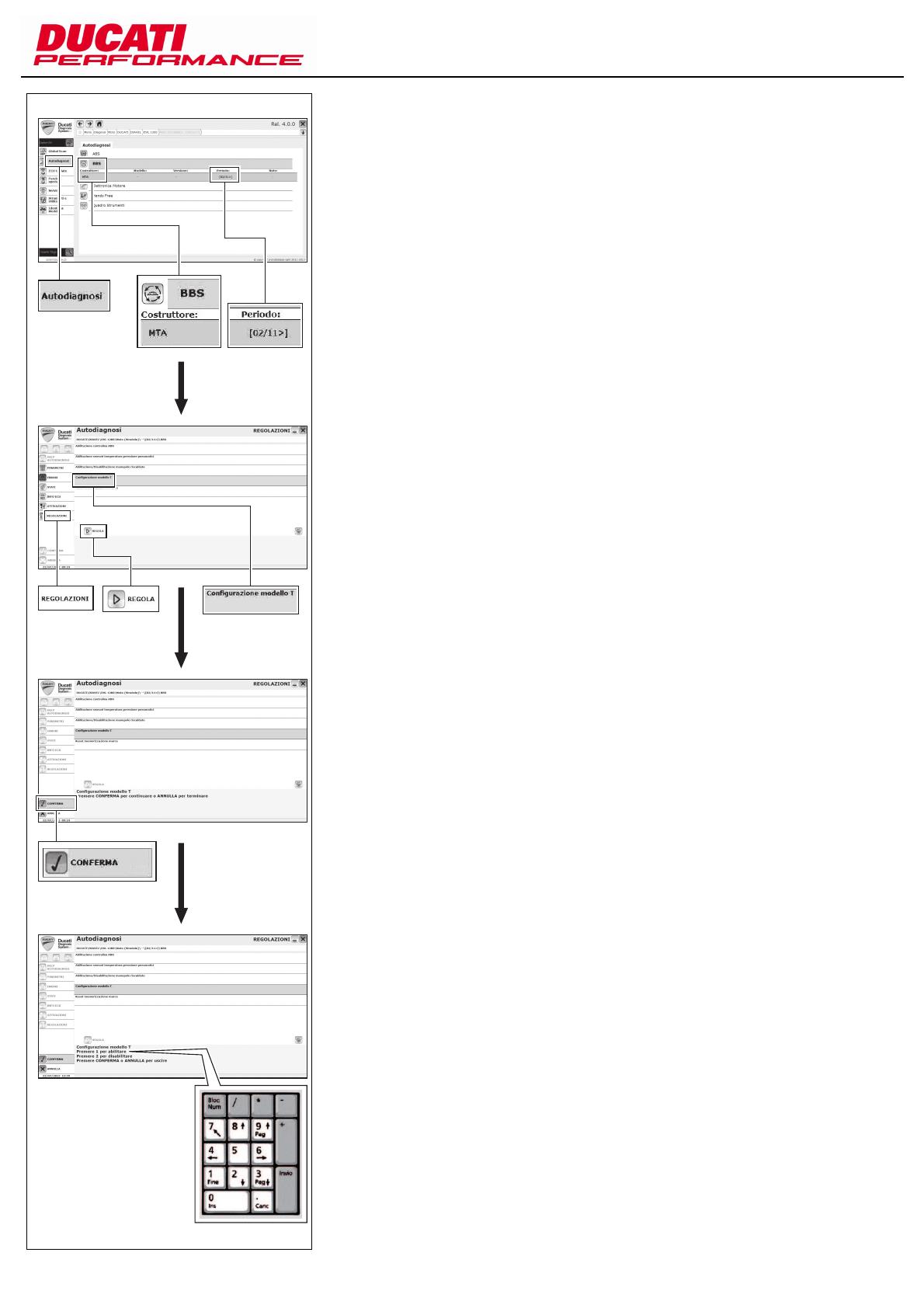
Turn indicators and stop light
activation
Connect the diagnostic tool to the data
acquisition socket (Z).
Select "DIAVEL" family (A1).
Select "DVL 1200" family (A2).
Select vehicle code "Motorcycle (Road use)
| -- | [ 02/11 > ]" (A3).
(A1)
(A2)
(A3)
Z
Attivazione indicatori di direzione
e luce stop
Collegare lo strumento di diagnosi al
connettore acquisizione dati (Z).
Selezionare la famiglia "DIAVEL" (A1).
Selezionare la versione "DVL 1200" (A2).
Selezionare il codice veicolo "Moto
(Stradale) | -- | [ 02/11 > ]" (A3).
Pag. - Page 11/17Cod. ISTR - 508 ED./ED. 01
Select "Self-Diagnosis" (A4).
Select "BBS" system (A4).
Select Manufacturer "MTA - - [02/11>]"
(A4).
Select "ADJUSTMENTS" (A5) from the
menu on the left.
Select "Model T configuration" (A5).
Press key "ADJUST" (A5).
Press green button "CONFIRM" (A6).
Press key "1" to enable T configuration
which allows to use turn indicators/stop
light as for Performance bags assembly kit
(A7).
(A4)
(A5)
(A6)
(A7)
Selezionare l'ambiente "Autodiagnosi" (A4).
Selezionare impianto "BBS" (A4).
Selezionare Costruttore "MTA - - [02/11>]"
(A4).
Nel menù di sinistra selezionare
"REGOLAZIONI" (A5).
Selezionare "Configurazione modello T"
(A5).
Premere il pulsante "REGOLA" (A5).
Premere il pulsante verde "CONFERMA"
(A6).
Premere il tasto "1" per abilitare la
configurazione T che prevede l'utilizzo degli
indicatori di direzione/luce stop come da kit
montaggio Borse Performance (A7).

Pag. - Page 12/17 Cod. ISTR - 508
ED./ED. 01
Wait for the operation to be completed and
make sure that the settings changes (A8)
are actually applied.
From "STATUSES", on the menu on the left,
you can select "Model configuration" and
make sure whether the status has been
changed from "base" to "T" (A9).
Note
If the "base" status is still active, it is
necessary to ensure that installed BBS
software is version 14 or higher and that the
Master Instrument Panel version is Micro
vr. 10 Flash vr. 07.
If that is not so, follow the software update
instructions of the BBS and Instrument
panel control unit/s (below) so as to install
the correct software versions for this kit.
Then repeat the "Model Configuration"
adjustment.
Caution
Check the correct activation of the
turn indicators and stop light.
The turn indicators and STOP light turn on
upon request through the left switch,
regardless of the stop light ON request
from brake lever.
Note
The turn indicators and stop light
must be correctly activated even if the
engine control unit software version is USA/
Canada.
(A8)
(A9)
Attendere il completamento dell'operazione
con la conferma sulla avvenuta modifica
delle impostazioni (A8).
Nel menù di sinistra, alla voce "STATI", è
possibile selezionare "Configurazione
modello" e verificare che il valore dello stato
sia modificato da "base" in "T" (A9).
Note
Se lo stato risulta ancora "base"
occorre verificare che la versione software
della BBS installata sia la 14 o successiva e
che la versione software del Cruscotto
Master sia Micro vr. 10 Flash vr. 07.
In caso contrario seguire le istruzioni di
aggiornamento software della/e centralina/
e BBS e Cruscotto (presenti di seguito) in
modo tale da installare le versioni di
software corrette per questo kit.
Quindi ripetere la regolazione
"Configurazione Modello".
Importante
Verificare la corretta attivazione degli
indicatori di direzione e della luce stop.
L'accensione degli indicatori di direzione
deve avvenire su richiesta da commutatore
sinistro in modo totalmente indipendente
rispetto alla richiesta di accensione luce
STOP da leva freno.
Note
La corretta attivazione degli indicatori
di direzione e della luce stop deve avvenire
anche se la versione software della
centralina controllo motore è USA/Canada.

Pag. - Page 13/17Cod. ISTR - 508 ED./ED. 01
Software update of BBS and
Instrument Panel.
Connect the diagnostic tool to the data
acquisition socket (Z).
Select "DIAVEL" family (B1).
Select "DVL 1200" version (B2).
Select vehicle code "Motorcycle (Road use)
| -- | [ 02/11 > ]" (B3).
(B1)
(B2)
(B3)
Z
Aggiornamento software della
centralina BBS e Cruscotto
Collegare lo strumento di diagnosi al
connettore acquisizione dati (Z).
Selezionare la famiglia "DIAVEL" (B1).
Selezionare la versione "DVL 1200" (B2).
Selezionare il codice veicolo "Moto
(Stradale) | -- | [ 02/11 > ]" (B3).

Pag. - Page 14/17 Cod. ISTR - 508
ED./ED. 01
Carry out a Global Scan and ensure that BBS
and Master DSB software versions are as
follows (B4):
If that is not so, update by using the update
procedure below.
Software update of BBS control
unit.
Select "DIAVEL" family (C1).
Select "SERVICE UPDATE DVL 1200"
version (C2).
Select vehicle code "Motorcycle (Road use)
| -- | [ 02/11 > ]" (C3).
Electronic control
unit
Software Version
MTA BBS Control
unit [02/11>]
0014
MAE Master
instrument panel
control unit
[02/11>]
10
(B4)
(C1)
(C2)
(C3)
Eseguire un Global Scan e verificare che i
software BBS e DSB Master siano i
seguenti (B4):
In caso contrario occorre procedere
all'aggiornamento utilizzando la modalità di
aggiornamento di seguito descritta.
Aggiornamento software della
centralina BBS
Selezionare la famiglia "DIAVEL" (C1).
Selezionare la versione "SERVICE UPDATE
DVL 1200" (C2).
Selezionare il codice veicolo "Moto (
Stradale ) | - - | [ 02/11 -> ]" (C3).
Centralina
Elettronica
Versione Software
Centralina BBS
MTA [02/11>]
0014
Centralina
strumentazione
Master MAE
[02/11>]
10

Pag. - Page 15/17Cod. ISTR - 508 ED./ED. 01
Select "ECU Update" (C4).
Select "BBS Reprogramming" (C4).
Select Manufacturer "MTA - - [02/11>]"
(C4).
Select "MAPS" (C5) from the menu on the
left.
Select "0803_T" (C5).
Press "ECU update" (C5).
When system requests a password, enter
"PERFORMANCE" (C6).
To confirm (C6), press "OK".
Wait for BBS control unit software
programming to be completed (C7).
(C4)
(C5)
(C6)
(C7)
Selezionare l'ambiente "ECU Update" (C4).
Selezionare "Riprogrammazione BBS" (C4).
Selezionare Costruttore "MTA - - [02/11>]"
(C4).
Nel menù di sinistra selezionare
"MAPPATURE" (C5).
Selezionare "0803_T" (C5).
Premere il pulsante "ECU update" (C5).
Alla richiesta di inserimento Password
utilizzare "PERFORMANCE" (C6).
Premere il pulsante "OK" per confermare
(C6).
Attendere il termine della programmazione
software centralina BBS (C7).

Pag. - Page 16/17 Cod. ISTR - 508
ED./ED. 01
Update of Master instrument
panel control unit software
Select "DIAVEL" family (D1).
Select "SERVICE UPDATE DVL 1200"
version (D2).
Select vehicle code "Motorcycle (Road use)
| -- | [ 02/11 > ]" (D3).
Select "ECU Update" (D4).
Select "Instrument panel Reprogramming"
(D4).
Select Manufacturer "MAE - - [02/11>]"
(D4).
(D1)
(D2)
(D3)
(D4)
Aggiornamento software della
centralina Cruscotto Master
Selezionare la famiglia "DIAVEL" (D1).
Selezionare la versione "SERVICE UPDATE
DVL 1200" (D2).
Selezionare il codice veicolo "Moto (
Stradale ) | - - | [ 02/11 -> ]" (D3).
Selezionare l'ambiente "ECU Update" (D4).
Selezionare "Riprogrammazione
Strumentazione" (D4).
Selezionare Costruttore "MAE - - [02/11>]"
(D4).

Pag. - Page 17/17Cod. ISTR - 508 ED./ED. 01
Select "MAPS" (D5) from the menu on the
left.
Select "_MSTF07" (D5).
Press "ECU update" (D5).
Wait for Master Instrument panel software
programming to be completed (D6).
Disconnect the diagnostic tool from the
data acquisition socket.
Reassemble rear mudguard as specified in
“Rear mudguard assembly”.
Reassemble seat as specified in “Seat
assembly”.
(D5)
(D6)
Nel menù di sinistra selezionare
"MAPPATURE" (D5).
Selezionare "_MSTF07" (D5).
Premere il pulsante "ECU update" (D5).
Attendere il termine della programmazione
software Cruscotto Master (D6).
Scollegare lo strumento di diagnosi dal
connettore acquisizione dati.
Rimontare il parafango posteriore seguendo
quanto riportato al capitolo "Montaggio
parafango posteriore".
Rimontare la sella seguendo quanto
riportato al capitolo "Montaggio sella".

Modèles de référence: / Bezugsmodelle:
Les pièces surlignées en gris et la référence numérique (Ex. ) représentent l'accessoire à
installer et les composants de montage éventuels fournis en kit. Les pièces avec référence
alphabétique (Ex. ) représentent les composants d'origine présents sur le motocycle.
Pour une lecture rapide et rationnelle ont été utilisés des symboles qui mettent en évidence les
situations exigeant une attention particulière, les conseils pratiques ou bien encore de simples
informations. Toutes les indications droite ou gauche se réfèrent au sens de marche la moto.
Die grau gekennzeichneten Bestandteile mit numerischem Bezug (Bsp. ) geben das zu
installierende Bestandteil und die eventuellen, im Kit enthaltenen Montagekomponenten wieder.
Die Bestandteile mit alphabetischem Bezug (Bsp. ) geben die Original-Bestandteile wieder,
die am Motorrad verbaut wurden. Im Sinne einer schnellen und rationellen Erfassung beim Lesen
wurden Symbole verwendet, die auf Situationen hinweisen, bei denen maximale
Aufmerksamkeit geboten ist, oder die praktische Empfehlungen bzw. einfache Informationen
hervorheben. Alle Angaben wie „rechts” oder „links” beziehen sich auf die Fahrtrichtung des
Motorrads.
Attention / Achtung
La non-observance des instructions reportées ci-dessous peut créer une situation
dangereuse et provoquer de graves lésions personnelles voire la mort. / Eine Nichtbeachtung der
hier wiedergegebenen Anweisungen kann Gefahrensituationen schaffen und zu schweren
Verletzungen und auch zum Tod führen.
Important / Wichtig
Indique la possibilité d'endommager le véhicule et/ou ses composants si les instructions
reportées ci-dessous ne sont pas suivies. / Weist darauf hin, dass bei Nichteinhaltung der hier
wiedergegebenen Anweisungen die Möglichkeit für Schäden am Fahrzeug und/oder seiner
Komponenten besteht.
Remarques / Hinweis
Fournit des informations utiles sur l'opération en cours. / Übermittelt nützliche
Informationen zum betreffenden Arbeitseingriff.
2
A
2
A
Code. ISTR / Art.-Nr. ANLEIT - 508 Page - Seite 1/17
ISTR/ANLEIT - 508 ED./AUSG. 01
ED./AUSG. 01
Diavel
Kit valises semi-rigides latérales / Kit halbsteife Seitenkoffer - 96780011A
1 Sous-cadre support valises
2 Vis TBHC M8x45
3 Rattrapeur de jeu
4 Écrou annulaire
5 Câblage arrière gauche
6 Câblage arrière droit
7 Feu arrière
8 Clignotant arrière droit
9 Clignotant arrière gauche
10 Écrou autobloquant
11 Plot caoutchouc
12 Rondelle
13 Entretoise
14 Vis THB M5x22
15 Plaquette masse droite
16 Plaquette masse gauche
17 Vis TCHCF M8x30
1 Kofferhalterahmen
2 Linseninnensechskantschraube M8x45
3 Spielausgleicher
4 Nutmutter
5 Hintere Verkabelung, links
6 Hintere Verkabelung, rechts
7 Rücklicht
8 Hinterer Blinker, rechts
9 Hinterer Blinker, links
10 Selbstsichernde Mutter
11 Gummielement
12 Unterlegscheibe
13 Distanzstück
14 Geflanschte Zylinderschraube M5x22
15 Masseplättchen, rechts
16 Masseplättchen, links
17 Spezial-Innensechskantschraube
M8x30
16
9
2
5
8
12
17
3
17
10
11
13
15
7
13
11
10
12
14
3
4
2
4
1
6
14
Page - Seite 2/17
Code. ISTR / Art.-Nr. ANLEIT - 508
ED./AUSG. 01
18 Verschluss für Bohrung M8
19 Verschlusskappe für Anschluss
20 Buchse zur Kofferbefestigung, kurz
21 Befestigung an Krone
22 Griff
23 Rückstrahler
24 Geflanschte Innensechskantschraube
M8x25
25 Flache Unterlegscheibe
26 Flachsenkkopfschraube mit
Innensechskant M6x20
27 Innensechskantschraube M6x20
28 Buchse zur Kofferbefestigung, lang
29 Koffer, rechts
30 Koffer, links
31 Wärmeschutz für Koffer
32 Spezialschraube M5x16 (5 Stck.)
33 Unterlegscheiben (5 Stck.)
34 Distanzstück (5 Stck.)
35 Wasserdichter Schutzbeutel (2 Stck.)
18
29
34
19
28
1
20
32
33
18
31
23
26
20
18
21
27
30
22
35
26
21
20
20
24
25
27
28
18 Bouchon trou M8
19 Bouchon pour prise
20 Accrochage valises type court
21 Élément de fixation à couronne
22 Poignée
23 Catadioptre arrière
24 Vis TCHCF M8x22
25 Rondelle plate
26 Vis TEPHE M6x20
27 Vis TCHC M6x20
28 Accrochage valises type long
29 Valise droite
30 Valise gauche
31 Pare-chaleur valise
32 Vis TBHCF M5x16 (q.té 5)
33 Rondelle (q.té 5)
34 Entretoise (q.té 5)
35 Sac imperméable (q.té 2)

Page - Seite 3/17Code. ISTR / Art.-Nr. ANLEIT - 508 ED./AUSG. 01
Hinweis
Vor Beginn der Arbeitseingriffe die
Warnhinweise auf der ersten Seite auf-
merksam durchlesen.
Achtung
Die nachstehend beschriebenen Ar-
beitseingriffe müssen von einem Fachtech-
niker oder einer DUCATI Vertragswerkstatt
ausgeübt werden.
Abnahme der Original-Teile
Achtung
Folgende Arbeitseingriffe können,
falls nicht fachgerecht ausgeübt, die
Sicherheit des Fahrers gefährden.
Die Sitzbank (A) den Angaben im Kapitel
„Abnahme der Sitzbank¨ gemäß abnehmen
Den hinteren Kotflügel den Angaben im
Kapitel„Abnahme des hinteren Kotflügels”
gemäß abnehmen.
Die sechs Schrauben (B) lösen, dann den
Deckel (A) abnehmen.
Die Schrauben (E) lösen, dann den
Schlüsselblock (F) aushaken.
Die vier Schrauben (H) lösen, dann die
Blockeinheit (G) entfernen und die
Unterlegscheiben (I) aufnehmen.
Die Schraube (G1) lösen, dann den Knauf
(G2), die Feder (G3) und den Stift (G4) aus
dem Block (G) nehmen.
Den hinteren Haltegriff (D) bis auf Anschlag
herausziehen und anheben, um ihn aus
dem Sperrzahn (L1) zu lösen.
Die Stecker (P6) und (N6) der Rücklichter (P)
und (N) abziehen.
Die Schraube (P4) gemeinsam mit
Unterlegscheibe (P5) lösen, dann das
rechte Rücklicht (P) nach hinten abziehen.
Die Distanzstücke (P1) und (P3) sowie das
Gummielement (P2) aus dem Staufach (L)
nehmen.
Die Schraube (N4) gemeinsam mit
Unterlegscheibe (N5) lösen, dann das linke
Rücklicht (N) nach hinten abziehen.
Die Distanzstücke (N1) und (N3) sowie das
Gummielement (N2) aus dem Staufach (L)
entfernen.
Die Gummielemente (M) aus dem Staufach
(L) entfernen.
C
P
B
D
C
A
L
G
E
F
H
G1
G2
G3
G4
I
G1
P1
P6
L
M
P2 P3 P5 N4 N5
N3
N2
N1
N
M
N6
Remarques
Avant de commencer l’opération, lire
attentivement les avertissements reportés
sur la première page.
Attention
Les opérations reportées ci-après doi-
vent être effectuées par un technicien spé-
cialisé ou par un atelier agréé DUCATI.
Dépose composants d'origine
Attention
Une mauvaise exécution des
opérations ci-dessous peut préjudicier à la
sécurité du pilote.
Déposer la selle en suivant la procédure
indiquée au chapitre « Dépose selle ».
Déposer le garde-boue arrière en suivant les
instructions indiquées au chapitre « Dépose
garde-boue arrière ».
Dévisser les six vis (B) et déposer le
couvercle (A).
Dévisser les vis (E) et décrocher le barillet
(F).
Dévisser les quatre vis (H) et déposer
l'ensemble barillet (G) en récupérant les
rondelles (I).
Dévisser la vis (G1) et déposer la poignée
(G2), le ressort (G3) et la vis sans tête (G4)
du barillet (G).
Sortir la poignée arrière (D) jusqu'en butée
et soulever pour la dégager de l'ergot
d'arrêt (L1).
Débrancher les connecteurs (P6) et (N6)
des feux arrière (P) et (N).
Desserrer la vis (P4) avec rondelle (P5) et
sortir vers la partie arrière le feu droit (P).
Déposer les entretoises (P1), (P3) et le plot
caoutchouc (P2) du bac vide-poches (L).
Desserrer la vis (N4) avec rondelle (N5) et
sortir le feu gauche (N) vers la partie arrière.
Déposer les entretoises (N1), (N3) et le plot
caoutchouc (N2) du bac vide-poches (L).
Déposer les plots en caoutchouc (M) du bac
vide-poches (L).
/