Moog Videolarm PurgeDome PDW7CS-9 Manual do usuário
- Categoria
- Câmeras de segurança
- Tipo
- Manual do usuário
Este manual também é adequado para

81-IN5410
01-30-2009
www.videolarm.com
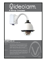
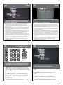
Explosion-Proof: Purge/ Pressurization Unit
PDW7CN-9 IP Network Ready 7” Explosion-Proof PurgeDome™ Outdoor
PTZ Camera Systems for Hazardous environments UL
approved for Class 1, Division II applications. Includes
Purging System and Lines. With 23x zoom Day/Night
camera, MPEG-4 & MJPEG video compression,
Full D1. Clear dome, with 24VAC input, heater/ blower
PDW7CS-9 Analog 7” Explosion Proof PurgeDome™ Outdoor PTZ Camera
Systems for Hazardous environments UL approved for
Class 1, Division II applications. Includes Purging System
and Lines. With 23x zoom Day/Night camera, MPEG-4 &
MJPEG video compression, Full D1. Clear dome, with
24VAC input, heater/ blower
PDW7CS-9
Before attempting to connect or operate this product, please read these
instructions completely. To be used with the 81-IN5409 Instruction Manual.

IMPORTANT SAFEGUARDS SAFETY PRECAUTIONS
UNPACKING
SERVICE
1 Read these instructions.
2 Keep these instructions.
3 Heed all warnings
4 Follow all instructions.
5 Do not use this apparatus near water.
6 Clean only with damp cloth.
7 Do not block any of the ventilation openings. Install in accordance with the
manufacturers instructions.
8 Cable Runs- All cable runs must be within permissible distance.
9 Mounting - This unit must be properly and securely mounted to a supporting
structure capable of sustaining the weight of the unit.
Accordingly:
a. The installation should be made by a qualified installer.
b. The installation should be in compliance with local codes.
c. Care should be exercised to select suitable hardware to install the unit, taking into
account both the composition of the mounting surface and the weight of the
unit.
10 Do not install near any heat sources such as radiators, heat registers, stoves, or other
apparatus ( including amplifiers) that produce heat.
11 Do not defeat the safety purpose of the polarized or grounding-type plug. A
polarized plug has two blades with one wider than the other. A grounding type
plug has two blades and a third grounding prong. The wide blade or the third
prong are provided for your safety. When the provided plug does not fit into your
outlet, consult an electrician for replacement of the obsolete outlet.
12 Protect the power cord from being walked on or pinched particularly at plugs,
convenience receptacles, and the point where they exit from the apparatus.
13 Only use attachment/ accessories specified by the manufacturer.
14 Use only with a cart, stand, tripod, bracket, or table specified by the manufacturer,
or sold with the apparatus. When a cart is used, use caution when moving the cart/
apparatus combination to avoid injury from tip-over.
15 Unplug this apparatus during lighting storms or when unused for long periods of time.
16 Refer all servicing to qualified service personnel. Servicing is required when the
apparatus has been damaged in any way, such as power-supply cord or plug is
damaged, liquid has been spilled of objects have fallen into the apparatus, the
apparatus has been exposed to rain or moisture, does not operate normally, or
has been dropped.
Be sure to periodically examine the unit and the supporting structure to make sure that the
integrity of the installation is intact. Failure to comply with the foregoing could result in the
unit separating from the support structure and falling, with resultant damages or injury to
anyone or anything struck by the falling unit.
Unpack carefully. Electronic components can be
damaged if improperly handled or dropped. If an item
appears to have been damaged in shipment, replace
it properly in its carton and notify the shipper.
Be sure to save:
1 The shipping carton and packaging material.
They are the safest material in which to make
future shipments of the equipment.
2 These Installation and Operating Instructions.
If technical support or service is needed, contact us
at the following number:
The lightning flash with an arrowhead
symbol, within an equilateral triangle, is
intended to alert the user to the presence
of non-insulated “dangerous voltage”
within the product’s enclosure that may be
of sufficient magnitude to constitute a risk
to persons.
Este símbolo se piensa para alertar al usuario a la
presencia del “voltaje peligroso no-aisIado” dentro del
recinto de los productos que puede ser un riesgo de
choque eléctrico.
Ce symbole est prévu pour alerter I’utilisateur à la
presence “de la tension dangereuse” non-isolée dans la
clôture de produits qui peut être un risque de choc
électrique.
Dieses Symbol soll den Benutzer zum Vorhandensein der
nicht-lsolier “Gefährdungsspannung” innerhalb der
Produkteinschließung alarmieren die eine Gefahr des
elektrischen Schlages sein kann.
Este símbolo é pretendido alertar o usuário à presença
“di tensão perigosa non-isolada” dentro do cerco dos
produtos que pode ser um risco de choque elétrico.
Questo simbolo è inteso per avvertire I’utente alla
presenza “di tensione pericolosa” non-isolata all’interno
della recinzione dei prodotti che può essere un rischio di
scossa elettrica
.
The exclamation point within an equilateral
triangle is intended to alert the user to
presence of important operating and
maintenance (servicing) instructions in the
literature accompanying the appliance.
Este símbolo del punto del exclamation se piensa para
alertar al usuario a la presencia de instrucciones
importantes en la literatura que acompaña la
aplicación.
Ce symbole de point d’exclamation est prévu pour
alerter l’utilisateur à la presence des instructions
importantes dans la littérature accompagnant
l’appareil.
Dieses Ausruf Punktsymbol soll den Benutzer zum
Vorhandensein de wichtigen Anweisungen in der
Literatur alarmieren, die das Gerät begleitet.
Este símbolo do ponto do exclamation é pretendido
alertar o usuário à presença de instruções importantes
na literatura que acompanha o dispositivo.
Questo simbolo del punto del exclamaton è inteso per
avvertire l’utente alla presenza delle istruzioni importanti
nella letteratura che accompagna l'apparecchio.
TECHNICAL SUPPORT
AVAILABLE 24 HOURS
1- 800 - 554 -1124
RISK OF ELECTRIC SHOCK
DO NOT OPEN
CAUTION
CAUTION: TO REDUCE THE RISK OF
ELECTRIC SHOCK, DO NOT REMOVE
COVER ( OR BACK). NO USER- SERVICE-
ABLE PARTS INSIDE. REFER SEVICING TO
QUALIFIED SERVICE PERSONNEL.

LIMITEDWARRANTY FOR VIDEOLARM INC. PRODUCTS
VIDEOLARMINC. warrantsthis Productto be free fromdefectsin materialor workmanship,as follows:
PRODUCTCATEGORY PARTS LABOR
All Enclosures and Electronics Five (5) Years Five (5) Years
Pan/Tilts Three (3) Years **6 months if used in autoscan Three (3) Years **6 months if used in autoscan
Poles/PoleEvators Three (3) Years Three (3) Years
Warrior/Q-View/I.R. Illuminators Five (5) Years Five (5) Years
Controllers Five (5) Years Five (5) Years
Power Supplies Five (5) Years Five (5) Years
Accessory Brackets Five (5) Years Five (5) Years
During the labor warranty period, to repair the Product, Purchaser will either return the defective product, freight prepaid, or deliver it to Videolarm Inc.
Decatur GA. The Product to be repaired is to be returned in either its original carton or a similar package
an equal degree of protection with a
RMA # (Return Materials Authorization number) displayed on the outer box or packing slip. To obtain a RMA# you must contact our Technical Support
Team at 800.554.1124, extension 101. Videolarm will return the repaired Product freight prepaid to Purchaser. Videolarm is not obligated to provide
Purchaser with a substitute unit during the warranty period or at any time. After the applicable warranty period, Purchaser must pay all labor and/or
parts charges.
1.NOTIFICATIONOF CLAIMS: WARRANTYSERVICE:If Purchaser believes that the Product is defective in material or workmanship, then written notice
with an explanation of the claim shall be given promptly by Purchaser to Videolarm but all claims for warranty service must be made within the
warranty period. If after investigation Videolarm determines that the reported problem was not covered by the warranty, Purchaser shall p
ay Videolarm
for the cost of investigating the problem at its then prevailing per incident billable rate. No repair or replacement of any Product or part thereof shall
extend the warranty period as to the entire Product. The
warranty on the repaired part only shall be in for a period of ninety (90) days
following the repair or replacement of that part or the remaining period of the Product parts warranty, whichever is greater.
2.EXCLUSIVE REMEDY: ACCEPTANCE:Purchaser’s exclusive remedy and Videolarm’s sole obligation is to supply (or pay for) all labor necessary to repair
any Product found to be defective within the warranty period and to supply, at no extra charge, new or rebuilt replacements for defective parts.
3.EXCEPTIONS TO LIMITED WARRANTY: Videolarm shall have no liability or obligation to Purchaser with respect to any Product requiring service
during the warranty period which is subjected to any of the following: abuse, improper use: negligence, accident, lightning damage or other acts
of God (i.e., hurricanes, earthquakes),
failure of the end-user to follow the directions outlined in the product instructions, failure of the
end-user to follow the maintenance procedures recommended by the International Security Industry Organization, written in product instructions,
or recommended in the service manual for the Product. Furthermore, Videolarm shall have no liability where a schedule is
for regular
replacement or maintenance or cleaning of certain parts (based on usage) and the end-user has failed to follow such schedule; attempted repair by
personnel; operation of the Product outside of the published environmental and electrical parameters, or if such Product’s original
(trademark, serial number) markings have been defaced, altered, or removed. Videolarm excludes from warranty coverage Products sold
AS IS and/or WITH ALL FAULTS and excludes used Products which have not been sold by Videolarm to the Purchaser. All software and accompanying
documentation furnished with, or as part of the Product is furnished “AS IS”(i.e., without any warranty of any kind), except where expressly provided
otherwise in any documentation or license agreement furnished with the Product.
4.PROOF OF PURCHASE:The Purchaser’s dated bill of sale must be retained as evidence of the date of purchase and to establish warranty eligibility.
DISCLAIMEROF WARRANTY
EXCEPT FOR THE FOREGOING WARRANTIES, VIDEOLARM HEREBY DISCLAIMS AND EXCLUDES ALL OTHER WARRANTIES, EXPRESS OR IMPLIED,
INCLUDING, BUT NOT LIMITED TO ANY AND/OR ALL IMPLIED WARRANTIES OF MERCHANTABILITY, FITNESS FOR A PARTICULAR PURPOSE AND/OR ANY WARRANTY WITH
REGARD TO ANY CLAIM OF INFRINGEMENT THAT MAY BE PROVIDED IN SECTION 2-312(3) OF THE UNIFORM COMME
RCIAL CODE AND/OR IN ANY OTHER COMPARABLE
STATE STATUTE. VIDEOLARM HEREBY DISCLAIMS ANY REPRESENTATIONS OR WARRANTY THAT THE PRODUCT IS COMPATIBLE WITH ANY COMBINATION OF NON-VIDEOLARM
PRODUCTS OR NON-VIDEOLARM RECOMMENDED PRODUCTS PURCHASER CHOOSES TO CONNECT TO PRODUCT.
LIMITATION OF LIABILITY
THE LIABILITY OF VIDEOLARM, IF ANY, AND PURCHASER’S SOLE AND EXCLUSIVE REMEDY FOR DAMAGES FOR ANY CLAIM OF ANY KIND
WHATSOEVER, REGARDLESS OF THE LEGAL THEORY AND WHETHER ARISING IN TORT OR CONTRACT, SHALL NOT BE GREATER THAN THE ACTUAL PURCHASE PRICE OF THE
PRODUCT WITH RESPECT TO WHICH SUCH CLAIM IS MADE. IN NO EVENT SHALL VIDEOLARM BE LIABLE TO PURCHASER FOR ANY SPECIAL, INDIRECT, INCIDENTAL, OR
CONSEQUENTIAL DAMAGES OF ANY KIND INCLUDING, BUT NOT LIMITED TO, COMPENSATION, REIMBURSEMENT OR DAMAGES ON ACCOUNT OF THE LOSS OF PRESENT
OR PROSPECTIVE PROFITS OR FOR ANY OTHER REASON WHATSOEVER.
/tour operation
/tour operation
**6 months if used in autoscan
/tour operation
**6 months if used in autoscan
/tour operation
SView Series Five (5) Years
Five (5) Years
The limited warranty stated in these product instructions is subject to all of the following terms and conditions:
TERMS AND CONDITIONS

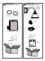
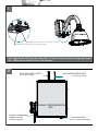
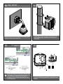
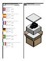
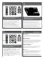
Content of Box
PURGE / PRESSURIZATION UNIT
SUPPLIED 1/4 “ & 3/8 ” POLY TUBING
Content of Box
PROTECTED
CAMERA
ENCLOSURE
PAN / TILT
DOME
HARDWARE

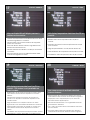
Unit is shipped with 100’ (max) flex tubing (3/8” & 1/4”) to connect enclosure to purge pressurized
unit. 2 fitting are provided as shown in the diagrams.
ENCLOSURE SUPPLY OUTLET
(3/8 “ Push-in Fitting)
ENCLOSURE REFERENCE INLET
(1/4 “ Push-in Fitting)
PURGED / PRESSURIZATION
UNIT
ELECTRICAL ALARM WIRING
CONDUIT AND SEAL
(Customer Supplied)
SYSTEM SUPPLY INLET
(3/8 “ SS Compression Fitting)
1
2

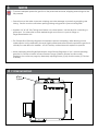
NOTES
• To ensure adequate protective gas flow to the protected enclosure, all piping and tubing must be
fully reamed.
• Precaution must be taken to prevent crimping and other damage to protective gas piping and
tubing. Caution must be used when opening/closing swing panel to prevent tubing kinks.
• Supplied 1/4” & 3/8” Poly Tubing have ferrule, nut & insert preset. Use that end for connecting to
power box. Cut other end to attain desired length and connect to push-in fittings on
Purge/Pressurization Unit.
• The Tamper-Proof (Primary) Regulator is intended to prevent tampering, while allowing a more
stable setpoint to be achieved in the small, tightly sealed enclosure where the protective gas flow is
critically low and difficult to stabilize. A 5/64” Hex Key or Allen Wrench is required to operate.
• When performing Initial Purge/Pressurization, adjust Primary Regulator to 5 psi. Normal operating
pressure is 2.5 inches of water at Dome Pressure Gauge. Balance Primary and Secondary
Regulators for continuous purge by alternately adjusting Primary (5 psi) and Secondary (2.5 inches
of water).
English
SYSTEM MOUNTING
14.7
O 0.32
4 places
PEPPERL FUCHS
+
10.0
3
4

LOW
SAFE
HIGH
0
.1
.2
.3
.4
.5
ENCLOSURE PRESSURE
SDOEN OF WOSTOE
5
4
3
2
1
500
400
300
20
10
OFF ON
METER
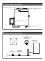
TUBING CONNECTION DIAGRAMS
DOME
PRESURE GAUGE
[ENCLOSURE]
ATMOSPHERIC
REFERENCE
EXP
PRESURE
SWITCH
PROTECTED
CAMERA
ENCLOSURE
REFERENCE
SYSTEM
SUPPLY
INLET
SUPPLY
PRIMARY
REGULATOR
SECONDARY
REGULATOR
FLOWMETER
TUBING CONNECTION DIAGRAMS
ENCLOSURE SUPPLY OUTLET
ENCLOSURE REFERENCE INLET
SYSTEM SUPPLY INLET
PEPPERL FUCHS
+
PURGE/PRESSURIZATION UNIT
5
6

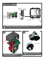
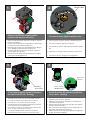
Open the metal power supply box on the camera
enclosure and remove cardboard packing
materials.
REMOVE INSERT
Carefully unpack both boxes and compare
with parts list.
POLE MOUNT CLIPS
POWER
SUPPLY
BOX
PAN
TILT
UNIT
DOME
TRIM
RING
CAMERA
ENCLOSURE
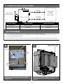
SET-UP PROCEDURE
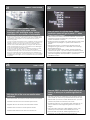
• See supplied Model 1001A Installation and Operation Manual for Class I Purging Set-up.
The use of a temporary SCFH flowmeter is unnecessary. Use the permanently installed flowmeter on the swing
panel in the Purge/Pressurization Unit.
• See supplied Model 1001A Installation and Operation Manual for additional installation and operation information.
CONNECTION SIZES, LENGTHS & BENDS
System Supply Camera Supply Camera Reference
3/8” OD SS Tubing SUPPLIED SUPPLIED
Fully Reamed 3/8” Poly Tubing 1/4” Poly Tubing
MAXIMUM:
100 ft MAX
100 ft MAX
20 ft / 10 bends
GAS SUPPLY
(System Supply)
CAMERA
REFERENCE
CAMERA
SUPPLY
PROTECTED
CAMERA
ENCLOSURE
PEPPERL FUCHS
+
PURGE/PRESSURIZATION UNIT
7
8
9

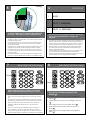
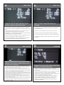
220-240VAC INPUT
110-120VAC INPUT
INPUT: (120VAC 1A
240VAC .5A)
The box is designed for either 120 or 240 VAC input
single phase. Line (L) and Neutral (N) wires should
be connected as marked on the board and
plugged into the corresponding voltage for the
input single phase.
Attach unit securely to the wall mount using (4) 3/8”
or 8mm hardware (not supplied).
WALL MOUNT:
The power box may be pole mounted with the
pole support clips. (Stainless steel straps not
provided).
10
11
12
120Vac
Input
240Vac
Input
Main
Switch
Connect incoming ground to ground post as
shown.
13

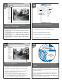
OUTPUT: (24VAC
84VA)
HEATERS
CAMERA
52 WATTS
MAX
32 WATTS
MAX
Internal resettable fuses are supplied for the main 24VAC output lines. Do not connect heaters
to camera output. The PB24 is not designed for 3 phase or 208V systems.
24Vac Power
To Housing
Optional 24Vac
Output
Main
Switch
Connect
Housing
Power
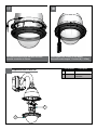
Remove Pan/ Tilt from shipping carton.
Install in base bracket in housing.
To secure in place, tighten captive screw.
See S-View Pan/Tilt instructions for additional
details.
• If required the Pan/ Tilt and dome may be installed
before mounting the entire assembly.
CAPTIVE SCREW
14
15
16

2
1
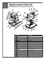
Replacement Parts List
Part Number Description
1 RP65PT851200 PAN TILT
2 PR25DCP71000 TRIM RING ASSEMBLY WITH
CLEAR DOME
To install the dome align the tabs and twist
counter clockwise to secure.
Hand tighten the screws on the dome.
Recommended torque 12 inches/lb (1.35Nm).
17
18

Before attempting to connect or operate this product,
please read these instructions completely.
www.videolarm.com
-
S - V I E W PA N / T I LT
Analog & IP
Installation and Operation Supplement:
81-IN5409
01-29-2009

S-VIEW PAN/ TILT
S-view: Analog 13 WATTS
S-view: IP 28 WATTS
MODELS: 12VDC
S-view: Analog 13 WATTS
S-view: IP 20 WATTS
Fuente De Alimentación De la Clase 2 Solamente.
MODELOS: 24 VAC
S-vista: Análogo 13 VATIOS
S-vista: IP 28 VATIOS
MODELOS: 12VDC
S-vista: Análogo 13 VATIOS
S-vista: IP 20 VATIOS.
Alimentation D'Énergie De la Classe 2 Seulement
MODÈLES : 24 VCA
S-vue : Analogue 13 WATTS
S-vue : IP 28 WATTS
MODÈLES : 12VDC
S-vue : Analogue 13 WATTS
S-vue : IP 20 WATTS.
Nur Kategorie 2 Spg. Versorgungsteil
MODELLE: 24 VAC
S-Ansicht: Analog 13 WATT
S-Ansicht: IP 28 WATT
MODELLE: 12VDC
S-Ansicht: Analog 13 WATT
S-Ansicht: IP 20 WATT.
Fonte De Alimentação Da Classe 2 Somente
MODELOS: 24 VAC
S-vista: Análogo 13 WATTS
S-vista: IP 28 WATTS
MODELOS: 12VDC
S-vista: Análogo 13 WATTS
S-vista: IP 20 WATTS
Gruppo di alimentazione Del Codice categoria 2 Soltanto
MODELLI: 24 VCA
S-vista: Analog 13 WATT
S-vista: IP 28 WATT
MODELLI: 12VDC
S-vista: Analog 13 WATT
S-vista: IP 20 WATT.
Electrical Specifications
Class 2 Power Supply Only
MODELS: 24 VAC
!!
Français
Deutsch
Italiano
Portuguese
Español
English
Content of Box

Remove Pan/Tilt from shipping carton.
Install in base bracket in housing.
• Quite Pan/Tilt del cartón del envío. Instale en soporte
bajo en la cubierta.
• Enlevez Pan/Tilt du carton d'expédition. Installez dans
la parenthèse basse dans le logement.
• Entfernen Sie Pan/Tilt vom Verschiffenkarton. Bringen
Sie in niedrigen Haltewinkel im Gehäuse an.
• Remova Pan/Tilt da caixa do transporte. Instale no
suporte baixo na carcaça.
• Rimuova Pan/Tilt dalla scatola di trasporto. Installi in
staffa bassa in alloggiamento.
CAPTIVE SCREW
To secure in place, tighten captive screw.
• Para asegurar en lugar, apriete el tornillo prisionero.
• Pour fixer en place, serrez la vis captive.
• Um im Platz zu sichern, ziehen Sie Sicherheitsschraube
fest.
• Para fixar-se no lugar, aperte o parafuso prisioneiro.
• Per fissare sul posto, stringa la vite prigioniera.
To set camera address locate PC board on
the side of Pan/Tilt unit. (Analog)
• Para fijar la dirección de la cámara fotográfica localice
el tablero de PC en el lado de la unidad de Pan/Tilt.
• Pour placer l'adresse d'appareil-photo localisez le
panneau de PC du côté de l'unité de Pan/Tilt.
• Um Kameraadresse einzustellen lokalisieren Sie PC Brett
auf der Seite der Pan/Tilt Maßeinheit.
• Para ajustar o endereço da câmera encontre a placa
de PC no lado da unidade de Pan/Tilt.
• Per regolare l'indirizzo della macchina fotografica
individui il bordo del pc dal lato dell'unità di Pan/Tilt.
PC Board
located here
Use the 8 position Dip switch to set address
lower corner. (Analog)
• Utilice el interruptor dip de 8 posiciones para fijar una
esquina más baja de la dirección.
• Utilisez le contact DIP de 8 positions pour placer le
coin inférieur d'adresse.
• Benutzen Sie den 8 Position DIP-Schalter, um Adresse
unterere Ecke einzustellen.
• Use o interruptor de mergulho de 8 posições ajustar
um canto mais baixo do endereço.
• Utilizzi l'interruttore di tuffo di 8 posizioni per regolare il
angolo più basso di indirizzo.
?
Address Dip
Switches
Factory Settings
DO NOT ADJUST
1
2
43

OFF
ON
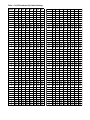
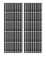
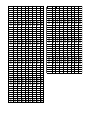
To set the address at “0” side the all switches off
as shown. See table in back for address 0-255
• Para fijar la dirección en "0" lados todos los interruptores
apagado según lo demostrado. Vea la tabla adentro detrás
para la dirección 0-255
• Pour placer l'adresse sur "0" côtés les tous les commutateurs
au loin comme montré. Voir le tableau dedans en arrière
pour l'adresse 0-255
• Die Adresse an "0" Seite weg einstellen die alle Schalter, wie
gezeigt. Sehen Sie Tabelle innen zurück für Adresse 0-255
• Para ajustar fora o endereço em "0" lados todos os interrup-
tores como mostrado. Veja a tabela dentro para trás para o
endereço 0-255
• Per regolare l'indirizzo "su 0" lati tutti gli interruttori fuori come
indicato. Veda la tabella dentro indietro per l'indirizzo 0-255
(Analog)
PROTOCOLS
The S-View Pan/Tilt support the above protocols.
This is done automatically no settings are
required.
• La ayuda de la S-Vista Pan/Tilt los protocolos antedichos. Se
requiere esto se hace automáticamente ningunos ajustes.
• L'appui de la S-Vue Pan/Tilt les protocoles ci-dessus. Ceci est
fait automatiquement aucuns arrangements sont exigés.
• Die S-Ansicht Pan/Tilt Unterstützung die oben genannten
Protokolle. Diesem wird automatisch keine Einstellungen
werden angefordert getan.
• A sustentação da S-Vista Pan/Tilt os protocolos acima. Isto é
feito automaticamente nenhuns ajustes é requerido.
• Il supporto di S-Vista Pan/Tilt i suddetti protocolli. Ciò è fatta
automaticamente nessun regolazioni è richiesta.
1 VL422
2 PELCO P 4800/9600
3 PELCO D 4800/9600
When using Videolarm controller; to enter the
menu; select the camera you wish to control.
• Al usar el regulador de Videolarm; para incorporar el menú;
seleccione la cámara fotográfica que usted desea contro-
lar.
• En utilisant le contrôleur de Videolarm ; pour écrire le menu ;
choisissez l'appareil-photo que vous souhaitez commander.
• Wenn Videolarm Steuerpult verwendet wird; das Menü
eintragen; wählen Sie die Kamera vor, die Sie steuern
möchten.
• Ao usar o controlador de Videolarm; para incorporar o
menu; selecione a câmera que você deseja controlar.
• Nel usando il regolatore di Videolarm; per entrare nel menu;
selezioni la macchina fotografica che desiderate controllare.
1
2
3
4
5
6
7 8
9
0
*
#
1, 2, 3...
F
Camera
MENU DRIVEN SETTINGS (Analog)
Then press 95 followed by the Preset
button ( ).
• Entonces la prensa 95 siguió por preestableció el
botón ( ).
• Alors la pression 95 a suivi de a préréglé le bouton
( ).
• Dann folgte Presse 95 von einstellte Taste ( ).
• Então a imprensa 95 seguiu pelo pré-ajustou a
tecla ( ).
• Allora la pressa 95 è seguito dal ha prestabilito il
tasto ( ).
1
2
3
4
5
6
7 8
9
0
*
#
1, 2, 3...
F
MENU DRIVEN SETTINGS (Analog)
Presets
5
6
8
7

IP INSTRUCTIONS: The factory default IP
address is : 192.168.0.200.
• INSTRUCCIONES DEL IP: El IP address del defecto de la
fábrica es: 192.168.0.200.
• INSTRUCTIONS D'IP : Le IP address de défaut d'usine est :
192.168.0.200.
• IP ANWEISUNGEN: Das Fabrikrückstellung IP address ist:
192.168.0.200.
• INSTRUÇÕES DO IP: O IP address do defeito da fábrica
é: 192.168.0.200.
• ISTRUZIONI DEL IP: Il IP address di difetto della fabbrica
è: 192.168.0.200.
(IP)
Control interface for IP PTZ control.
• Controle el interfaz para el control del IP PTZ.
• Commandez l'interface pour la commande d'IP PTZ.
• Steuern Sie Schnittstelle IP PTZ zur Steuerung.
• Controle a relação para o controle do IP PTZ.
• Controlli l'interfaccia per controllo del IP PTZ.
Select
PreSets
Lens
Functions
Pan/Tilt
functions
(also used
to scroll
camera
menu)
Use to
save or
remove
PreSets
(IP)
For Pan Tilt control click on the PTZ control
icon in top right corner.
• Para el control de la inclinación de la cacerola chasque
encendido el icono del control de PTZ en esquina derecha
superior.
• Pour le clic de commande d'inclinaison de casserole sur
l'icône de commande de PTZ dans le bon coin supérieur.
• Zur Wanne Neigungsteuerung klicken Sie an die PTZ
Steuerikone in der Rechteecke.
• Para o controle da inclinação da bandeja estale sobre o
ícone do controle de PTZ no canto direito superior.
• Per controllo di ribaltamento della vaschetta scatti sopra
l'icona di controllo di PTZ nel giusto angolo superiore.
(IP)
See IP Camera instruction CD for operation
details.
• Vea el CD de la instrucción de la cámara fotográfica
del IP para los detalles de la operación.
• Voir le CD d'instruction d'appareil-photo d'IP pour des
détails d'opération.
• Sehen Sie IP Kamera-Anweisung CD für Betrieb Details.
• Veja o CD da instrução da câmera do IP para detal-
hes da operação.
• Veda il CD di istruzione della macchina fotografica del
IP per i particolari di funzionamento.
(IP)
9
10
1211

DISPLAY / MENU
Use Up & Down control on the controller to
navigate through the menu. Pan left and right are
used to enter sub menus.
• Utilice para arriba y abajo controle en el regulador para navegar a través
del menú. La cacerola a la izquierda e a la derecha se utiliza para
incorporar menús secundarios.
• Épuisez et commandez vers le bas sur le contrôleur pour diriger par le menu.
La casserole à gauche et à droite sont utilisées pour écrire les menus
secondaires.
• Verwenden Sie oben u. steuern Sie unten auf dem Steuerpult, um durch das
Menü zu steuern. Verschieben Sie links und recht werden verwendet,
Vormenüs einzutragen.
• Use acima & controle para baixo no controlador para navigate através do
menu. Garimpe esquerdo e direito são usados incorporar menus
secundários.
• Consumi & giù controlli sul regolatore per traversare attraverso il menu. La
vaschetta a destra e a sinistra è utilizzata per entrare nei menu secondari..
DISPLAY / COMPASS
Use this submenu to activate compass heading. Press
zoom in to turn on, zoom out to turn off, Pan Left to exit.
• Utilice este submenu para activar el título de compás. Presione el zumbido
adentro para girarse, zumbido hacia fuera a dan vuelta apagado,
cacerola izquierda a la salida.
• Employez ce submenu pour activer le titre de boussole. Serrez le
bourdonnement dedans pour se tourner dessus, bourdonnement dehors
vers se tournent au loin, casserole gauche vers la sortie.
• Verwenden Sie dieses submenu, um Kompaßsteuerkurs zu aktivieren.
Betätigen Sie Zoom innen, um, Zoom heraus an an zu wenden wenden
weg, die Wanne, die an Ausgang link ist.
• Use este submenu ativar o título de compasso. Pressione o zumbido dentro
para girar sobre, zumbido para fora para desligam, bandeja esquerda
para a saída.
• Usi questo submenu per attivare l'intestazione di bussola. Premi lo zoom
dentro per girarsi sopra, zoom fuori verso si girano fuori, vaschetta di sinistra
verso l'uscita.
DISPLAY / SET NORTH
Use the “Zoom In” botton to set calibration.
Display will show OK.
• Utilice el "zumbido en" botton para fijar la calibración. La exhibición
demostrará MUY BIEN.
• Employez l'"bourdonnement dans" le botton pour placer le calibrage.
L'affichage montrera BIEN.
• Benutzen Sie den "Zoom" im botton, um Kalibrierung einzustellen.
Anzeige stellt O.K. dar.
• Use o "zumbido" no botton ajustar a calibração. A exposição mostrará
ESTÁ BEM.
• Usi "lo zoom" nel botton per regolare la calibratura. L'esposizione
mostrerà BENE.
DISPLAY / POSITION
A numeric camera position is shown on
monitor. With “Position” activated.
• Una posición numérica de la cámara fotográfica se
demuestra respecto a monitor. Con la "Posición" activó.
• Une position numérique d'appareil-photo est montrée
sur le moniteur. Avec l'"Position" a activé.
• Eine numerische Kameraposition wird auf Monitor
gezeigt. Wenn "Position" aktiviert ist.
• Uma posição numérica da câmera é mostrada no
monitor. Com "Posição" ativou.
• Una posizione numerica della macchina fotografica è
indicata sul video. Con "Posizione" ha attivato.
13
14
1615

DISPLAY / ADDRESS
When activated this will display camera’s
address on the monitor.
• Cuando está activado esto exhibirá la dirección de la
cámara fotográfica en el monitor.
• Quand activé ceci montrera l'adresse de l'appareil-
photo sur le moniteur.
• Wenn Sie diesem aktiviert werden, zeigt Adresse der
Kamera auf dem Monitor an.
• Quando ativado isto indicará o endereço da câmera
no monitor.
• Una volta attivato questo visualizzerà l'indirizzo della
macchina fotografica sul video.
DISPLAY / TEMP.
Will display temperature data from Pan/Tilt on
monitor.
• Exhibirá datos de la temperatura de Pan/Tilt en
monitor.
• Montrera des données de la température de Pan/Tilt
sur le moniteur.
• Zeigt Temperaturdaten von Pan/Tilt auf Monitor an.
• Indicará dados da temperatura de Pan/Tilt no monitor.
• Visualizzerà i dati di temperatura da Pan/Tilt sul video.
DISPLAY / PRESSURE
Will display pressure data from Pan/Tilt on
monitor. This feature is only available on
select models.
• Exhibirá datos de la presión de Pan/Tilt en monitor. Esta
característica está solamente disponible en modelos
selectos.
• Montrera des données de pression de Pan/Tilt sur le
moniteur. Ce dispositif est seulement disponible sur les
modèles choisis.
• Zeigt Druckdaten von Pan/Tilt auf Monitor an. Diese
Eigenschaft ist auf auserwählten Modellen nur vorhanden.
• Indicará dados da pressão de Pan/Tilt no monitor. Esta
característica está somente disponível em modelos
seletos.
• Visualizzerà i dati di pressione da Pan/Tilt sul video. Questa
caratteristica è soltanto disponibile sui modelli prescelti.
CAMERA / MENU
Use camera menu to activate selected
camera features.
• Utilice el menú de la cámara fotográfica para activar
características seleccionadas de la cámara fotográfica.
• Employez le menu d'appareil-photo pour activer les
dispositifs choisis d'appareil-photo.
• Benutzen Sie Kameramenü, um vorgewählte Kameraei-
genschaften zu aktivieren.
• Use o menu da câmera ativar características seleciona-
das da câmera.
• Usi il menu della macchina fotografica per attivare le
caratteristiche selezionate della macchina fotografica.
17
18
20
19

CAMERA / STABILIZATION
Camera sub menu includes, image
stabilization, day/night mode, shutter,
backlight, AGC and digital zoom. Image
stabilization is not a feature of all cameras.
• El menú secundario de la cámara fotográfica incluye, estabilización de la
imagen, modo de day/night, obturador, contraluz, AGC y zumbido digital.
La estabilización de la imagen no es una característica de todas las
cámaras fotográficas.
• Le menu secondaire d'appareil-photo inclut, stabilisation d'image, mode de
day/night, obturateur, contre-jour, AGC et bourdonnement numérique. La
stabilisation d'image n'est pas un dispositif de tous les appareils-photo.
• Kameravormenü schließt, Bildausgleichung, day/night Modus, Blendenver-
schluß, Hintergrundbeleuchtung, AGC und digitaler Zoom ein. Bildausgleic-
hung ist nicht eine Eigenschaft aller Kameras.
• O menu secundário da câmera inclui, estabilização da imagem, modali-
dade de day/night, obturador, luminoso, AGC e zumbido digital. A
estabilização da imagem não é uma característica de todas as câmeras.
• Il menu secondario della macchina fotografica include, stabilizzazione di
immagine, modo di day/night, otturatore, lampadina, AGC e zoom digitale.
La stabilizzazione di immagine non è una caratteristica di tutte le macchine
fotografiche.
ALARM / MENU
Use sub menu to activate alarm. When
enabled camera will go to preset “1” when
alarm input is closed.
• Utilice el menú secundario para activar el alarmar. Cuando está
permitida la cámara fotográfica irá a preestablecer "1" cuando la
entrada del alarmar es cerrada.
• Employez le menu secondaire pour activer l'alarme. Quand permis
l'appareil-photo ira prérégler "1" quand l'entrée d'alarme est
fermée.
• Benutzen Sie Vormenü, um Warnung zu aktivieren. Wenn sie
ermöglicht wird, geht Kamera, "1" einzustellen, wenn Warnung
Eingang geschlossen ist.
• Use o menu secundário ativar o alarme. Quando permitida a
câmera irá pré-ajustar "1" quando a entrada do alarme é closed.
• Usi il menu secondario per attivare l'allarme. Una volta permessa la
macchina fotografica andrà prestabilire "1" quando l'input
dell'allarme è chiuso.
ZONE / SHOW
Will show title of the zone on monitor when
activated.
• Demostrará el título de la zona en monitor cuando está activado.
• Montrera le titre de la zone sur le moniteur quand activé.
• Zeigt Titel der Zone auf Monitor, wenn Sie aktiviert werden.
• Mostrará o título da zona no monitor quando ativado.
• Mostrerà il titolo della zona sul video una volta attivato.
ZONE / PRIV.
Turn on “PRIV” to activate; Rlimit will turn off
menu, to allow you to position right limit for
zone.
• Gire "PRIV" para activar; el rlimit dará vuelta apagado al menú,
para permitir que usted coloque el límite derecho para la zona.
• Allumez "PRIV" pour activer ; le rlimit arrêtera le menu, pour vous
permettre de placer la bonne limite pour la zone.
• Schalten Sie "PRIV" ein, um zu aktivieren; rlimit stellt Menü ab, um
Ihnen zu erlauben, rechte Begrenzung für Zone in Position zu
bringen.
• Gire sobre "PRIV" para ativar; o rlimit desligará o menu, para
permitir que você posicione o limite direito para a zona.
• Accenda "PRIV" per attivare; il rlimit spegnerà il menu, per
permettere che posizioniate il giusto limite per la zona.
21
22
2423

ZONE / LLIMIT
Llimit will “turn off” menu and allow you to
position camera for left limit of zone.
• Voluntad de Llimit "dar vuelta apagado" al menú y permitir que
usted coloque la cámara fotográfica para el límite izquierdo de la
zona.
• Volonté de Llimit "arrêter" le menu et vous permettre de placer
l'appareil-photo pour la limite gauche de la zone.
• Llimit Wille Menü "" abstellen und Ihnen erlauben, Kamera für linke
Begrenzung auf Zone in Position zu bringen.
• Vontade de Llimit "para desligar" o menu e para permitir que você
posicione a câmera para o limite esquerdo da zona.
• Volontà di Llimit "spegnere" menu e permettere che posizioniate
macchina fotografica per il limite di sinistra della zona.
ZONE / TITLE
Shows on menu screen title characters
selected.
• Demostraciones en los caracteres del título de la pantalla de
menú seleccionados.
• Expositions sur des caractères de titre d'écran menu choisis.
• Erscheinen auf den Menüschirm-Titelbuchstaben vorgewählt.
• As mostras em caráteres do título da tela de menu selecionaram.
• Le esposizioni sui caratteri di titolo dello schermo di menu hanno
selezionato.
ZONE / SET TITLE
Allow you to select title characters. Pan left or right to
change character position. Use tilt up/down to show
characters. Press zoom in to set title-exit menu zoom
out will restore to original title.
• Permita que usted seleccione caracteres del título. Filtre izquierdo o derecho
cambiar la posición de carácter. Utilice la inclinación up/down para demostrar
caracteres. El zumbido de la prensa adentro para fijar el zumbido del menú de la
ti'tulo-salida hacia fuera restaurará al título original.
• Permettez-vous de choisir des caractères de titre. Filtrez gauche ou droit de
changer la position d'impression. Employez l'inclinaison haut/bas pour montrer des
caractères. Le bourdonnement de pression dedans pour placer le bourdonnement
de menu de titre-sortie dehors reconstituera au titre original.
• Erlauben Sie Ihnen, Titelbuchstaben vorzuwählen. Verschieben Sie links oder recht,
Zeichenstelle zu ändern. Verwenden Sie die Neigung, die, um Buchstaben zu zeigen
Auf-/Ab ist. Der Presse Zoom innen, zum von von Titel-Ausgang Menü Zoom heraus
einzustellen stellt zum ursprünglichen Titel wieder her.
• Permita que você selecione caráteres do título. Garimpe esquerdo ou direito para
mudar a posição de caráter. Use a inclinação up/down mostrar caráteres. O
zumbido da imprensa dentro para ajustar o zumbido do menu da título-saída para
fora restaurará ao título original.
• Permetta che selezioniate i caratteri di titolo. Filtri di sinistra o di destra per cambiare
la posizione del carattere. Usi l'inclinazione up/down per mostrare i caratteri. Lo
zoom della pressa dentro per regolare lo zoom del menu dell'titolo-uscita fuori
ristabilirà al titolo originale.
SYSTEM INFO
Displays Pan version, Tilt version, current Pan
position, and current Tilt position.
• Versión de la cacerola de las exhibiciones, versión de la
inclinación, posición actual de la cacerola, y posición actual de
la inclinación.
• Version de casserole d'affichages, version d'inclinaison, position
actuelle de casserole, et position actuelle d'inclinaison.
• Anzeigen Wanne Version, Neigungversion, gegenwärtige Wanne
Position und gegenwärtige Neigungposition.
• Versão da bandeja das exposições, versão da inclinação,
posição atual da bandeja, e posição atual da inclinação.
• Versione della vaschetta delle esposizioni, versione di
inclinazione, attuale posizione della vaschetta ed attuale
posizione di inclinazione.
25
26
2827
A página está carregando ...
A página está carregando ...
A página está carregando ...
A página está carregando ...
A página está carregando ...
A página está carregando ...
A página está carregando ...
-
 1
1
-
 2
2
-
 3
3
-
 4
4
-
 5
5
-
 6
6
-
 7
7
-
 8
8
-
 9
9
-
 10
10
-
 11
11
-
 12
12
-
 13
13
-
 14
14
-
 15
15
-
 16
16
-
 17
17
-
 18
18
-
 19
19
-
 20
20
-
 21
21
-
 22
22
-
 23
23
-
 24
24
-
 25
25
-
 26
26
-
 27
27


Moog Videolarm PurgeDome PDW7CS-9 Manual do usuário
- Categoria
- Câmeras de segurança
- Tipo
- Manual do usuário
- Este manual também é adequado para
em outros idiomas
Artigos relacionados
Outros documentos
-
Moog FusionDome PFDW75T2N Installation And Operation Instructions Manual
-
Adesso 3377-15 Guia de usuario
-
Moog IRHW7C Installation And Operation Instructions Manual
-
 American Dynamics AD168 Supplementary Manual
-
Samsung SCC-C7478P Manual do usuário
-
Samsung SCC-C6323N Manual do usuário
-
Videotec MAXIMUS MPX Manual do usuário
-
Vivotek AE-211 Manual do usuário
-
Yamaha CS-700 Guia de usuario
-
Avigilon ENC-4P-H264 Guia de instalação
