A página está carregando...

Power Booster (PB)
Electronic Low Voltage Interface (ELVI)
Fluorescent Dimming Ballast Interface (FDBI)
Installation Instructions — Please Read
PB ELVI FDBI
Incandescent
Magnetic Low Voltage
Neon/Cold Cathode
Lutron Tu-Wire
®
Dimming Ballast
Electronic Low Voltage Lutron Hi-lume
®
or Eco-10 ™
Fluorescent Dimming Ballast
UP UPUP UPUP UP
®
Power Interfaces
030-739 8/1/02 2:22 PM Page 1

Unit
PB
ELVI
FDBI
120V
1920W/VA
16A
1000W/VA
8.3A
1920W/VA
16A
220-240V (AU)
2400W/VA
10A
1200W/VA
5A
2400W/VA
10A
230V (CE)
1840W/VA
†
8A
†
1200W/VA
5.2A
—
—
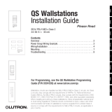
Interface shown with faceplate removed
2
UP UP
4.5 in.(115 mm)
4.5 in.(115 mm)
Danger! Always turn OFF the circuit breakers/MCB or
remove the main fuses from the power line before doing
any work. Failure to do so can result in serious personal
injury. More than one MCB can power this device.
Disconnect all power sources before servicing
unit.
This “load-side” equipment installs on the zone wiring between
the Control Unit* and the lighting load.
The PB increases a Control Unit’s zone load capacity for Incandes-
cent/Halogen (Tungsten), Magnetic Low Voltage, Neon/Cold Cath-
ode, and Lutron Tu-Wire load types.
The ELVI enables a zone of the Control Unit to control Electronic
Low-Voltage loads.
The FDBI enables a zone of the Control Unit to control fluorescent
loads with Lutron Hi-lume or Eco-10 phase-controlled dimming
ballasts.
The maximum load capacity for each Interface is shown in the
table that follows.
1. This Interface must be installed by a qualified electrician in
accordance with all applicable regulations.
2. Improper wiring can result in personal injury, damage to the
Interface, or damage to other equipment.
3. Up to two PB/ELVI/FDBIs per zone.
4. The PB/ELVI/FDBI must be mounted with arrows facing
upward to ensure adequate cooling.
5. PB: If using low-voltage incandescent fixtures, use only with
iron core (magnetic) transformers.
6. ELVI: Use only with solid-state (electronic) low-voltage
transformers that are manufacturer approved to be dimmed by
reverse phase control.
7. CAUTION! Dimmed magnetic low-voltage transformers: To
avoid excessively high current flow that can cause trans-
former overheating and failure, observe the following:
(a) Do not operate the Interface with all of the lamps
removed or with any lamps inoperative.
(b) Replace any burned out lamps immediately.
(c) Use only transformers that incorporate thermal protection
or fused primary windings.
8. ELVI/FDBI: These Interfaces contain a thermal device that
turns Off the Interface if overloaded. The Interface will turn On
when it cools.
* See Page 5 for other Lutron products that can be used to
control your PB/ELVI/FDBI.
†
1200W/VA and 5.2A for flush mount (as shown on pg. 6).
030-739 8/1/02 2:22 PM Page 2

HOT/LIVE
ZONE
NEUTRAL
4
3
2
1
USA: Class 2
IEC: PELV
DO NOT USE
H/L
N
HOT/LIVE
EARTH/GROUND
ZONE OUT
ZONE IN
NEUTRAL N
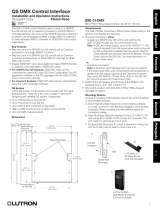
■ Turn power Off.
■ PB/ELVI: Connect standard switch between Hot/Live lead and
the load wire to test circuit.
■ FDBI: Connect standard switch between Hot/Live lead and the
Dimmed Hot/Live and switched Hot/Live leads of the ballast.
■ Turn power On and check for short or open circuits.
3
Test load for short circuits
Wiring Instructions
1. Turn power Off to the Control Unit and the feed to the PB,
ELVI, or FDBI!
2. Mount standard U.S. 2-gang wallbox* (available from Lutron,
P/N 241-641), 3 1/2 in. (87 mm) deep is strongly recom-
mended, 2 3/4 in. (68 mm) minimum. Allow at least 4 1/2 in.
(110 mm) clearance above/below Interfaces to ensure proper
heat dissipation.
3. Strip 1/2 in. (12 mm) insulation from all wires in wallbox and
wire as shown. All connections are made using #12 AWG
(2.5 mm
2
) wire. Power terminals can accept up to two
#12 AWG (2.5 mm
2
) wires. The NEUTRAL N terminal is for
the Control neutral, not the load neutral! The recommended
installation torque is 9.0 in.
●
lbs. (1.0 N
●
m) for line voltage
connections.
Single-Feed Wiring for PB/ELVI
120V and 220-240V
The PB/ELVI may be on the same circuit as the Control
Unit only if the total load does not exceed the rating of
the breaker.
Dual-Feed Wiring for PB/ELVI
120V and 220-240V
The load breaker/MCB can be on a different phase than the control
breaker/MCB.
* Wallbox may be flush mounted or surface mounted. If mount-
ing Interface in a panel, please refer to Panel Mounting section
for important information.
PB/ELVI FDBI
HOT/
LIVE
SWITCH
LOAD
HOT/LIVE
SWITCH
ORANGE
BLACK/BROWN
BALLAST
LOAD NEUTRAL
1/2 in. (12 mm)
HOT/LIVE
ZONE
NEUTRAL
4
3
2
1
USA: Class 2
IEC: PELV
DO NOT USE
H/L
N
HOT/LIVE
EARTH/GROUND
ZONE IN
NEUTRAL N
H/L
N
ZONE OUT
LOAD NEUTRAL
LOAD
LOAD
030-739 8/1/02 2:22 PM Page 3

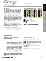
Single-Feed Wiring for PB/ELVI
230V
The PB/ELVI may be on the same circuit as the Control
Unit only if the total load does not exceed the rating of
the breaker.
HOT/LIVE
ZONE
NEUTRAL
4
3
2
1
USA: Class 2
IEC: PELV
DO NOT USE
H/L
N
HOT/LIVE
EARTH/GROUND
ZONE OUT
ZONE IN
NEUTRAL N
H/L
N
HOT/LIVE
ZONE
NEUTRAL
4
3
2
1
USA: Class 2
IEC: PELV
DO NOT USE
H/L
N
HOT/LIVE
EARTH/GROUND
ZONE OUT
ZONE IN
NEUTRAL N
Dual-Feed Wiring for PB/ELVI
230V
The load breaker/MCB can be on a different phase than the control
breaker/MCB
.
LOAD NEUTRAL
LOAD NEUTRAL
4
■ When using a PB to control a Lutron Tu-Wire dimming bal-
last, the associated zone on the GRAFIK Eye
®
3000 Series
Control Unit must be set to the Tu-Wire load type. Please
see the GRAFIK Eye 3000 Series Installer’s Guide for more
details.
■ The PB 230V must not be used with Tu-Wire ballasts
because the Tu-Wire load type is not available on 230V CE
models of the GRAFIK Eye Control Unit.
LOAD
LOAD
Tu-Wire Dimming Ballast
HOT/LIVE
ZONE
NEUTRAL
4
3
2
1
USA: Class 2
IEC: PELV
DO NOT USE
H/L
N
HOT/LIVE
EARTH/GROUND
ZONE IN
NEUTRAL N
H/L
N
ZONE OUT
DO NOT USE
HOT/LIVE
EARTH/GROUND
ZONE IN
NEUTRAL N
ZONE OUT
H/L
N
Dual-Feed Wiring for Two (2) PB/ELVI Interfaces on One
Zone - 120V and 220-240V
The load breaker/MCB can be on a different phase than the control
breaker/MCB.
LOAD NEUTRAL
LOAD
LOAD NEUTRAL
LOAD
030-739 8/1/02 2:22 PM Page 4

HOT/LIVE
ZONE
NEUTRAL
4
3
2
1
USA: Class 2
IEC: PELV
SW HOT/LIVE
H/L
N
HOT/LIVE
EARTH/GROUND
ZONE OUT
ZONE IN
NEUTRAL N
HOT/LIVE
ZONE
NEUTRAL
4
3
2
1
USA: Class 2
IEC: PELV
SW HOT/LIVE
H/L
N
HOT/LIVE
EARTH/GROUND
ZONE OUT
ZONE IN
NEUTRAL N
H/L
N
5
Single-Feed Wiring for FDBI
120V and 220-240V
The FDBI may be on the same circuit as the Control Unit if, and only if, the total
load does not exceed the rating of the breaker. Connect ZONE OUT only to Lutron
Hi-lume or Eco-10 Electronic Dimming Ballasts.
Dual-Feed Wiring for FDBI
120V and 220-240V
The load breaker/MCB can be on a different phase than the control breaker/MCB. Connect
ZONE OUT only to Lutron Hi-lume or Eco-10 Electronic Dimming Ballasts.
Lutron Products
The following Lutron products can also
be used to control your PB/ELVI/FDBI:
■ GRAFIK Eye GP Dimming Panels.
■ GRAFIK Eye LP Dimming Panels.
■ Homeworks Interactive
™
Remote Power
Panels.
■ Lutron fluorescent wallbox dimmers.
■ Please contact Lutron for use with
other Homeworks Interactive or
RadioRA
®
dimmers.
LOAD NEUTRAL
LOAD NEUTRAL
Lutron Hi-lume or
Eco-10 Ballast
Lutron Hi-lume or
Eco-10 Ballast
O
B
O = Orange
B = Black
O
B
O = Orange
B = Black
030-739 8/1/02 2:22 PM Page 5

6
1. Confirm all connections and mount the Interface using the screws provided.
2. Restore power to the system.
Mounting: Interface must be mounted vertically!
2-gang wallbox
Faceplate
Flush Mount Surface Mount
SW HOT/LIVE
HOT/LIVE
EARTH/GROUND
ZONE OUT
ZONE IN
NEUTRAL N
H/L
N
HOT/LIVE
ZONE
NEUTRAL
4
3
2
1
USA: Class 2
IEC: PELV
SW HOT/LIVE
H/L
N
HOT/LIVE
EARTH/GROUND
ZONE OUT
ZONE IN
NEUTRAL N
H/L
N
Dual-Feed Wiring for Two (2) FDBI Interfaces on One Zone
120V and 220-240V
The load breaker/MCB can be on a different phase than the control breaker/MCB. Connect ZONE OUT only to Lutron Hi-lume or Eco-10
Electronic Dimming Ballasts.
LOAD NEUTRAL
LOAD NEUTRAL
Lutron Hi-lume or
Eco-10 Ballast
Lutron Hi-lume or
Eco-10 Ballast
O
B
O
B
O = Orange
B = Black
030-739 8/1/02 2:22 PM Page 6

Symptom
Lights do not come on.
Lights turn on/off
unexpectedly.
Troubleshooting Guide
PB
ELVI
FDBI
4 1/2 in. (11 cm) MINIMUM
4 1/2 in. (11 cm) MINIMUM
Panel Mounting
■ The enclosure must be in accordance with all local and national electrical
codes.
■ Lutron does not recommend using a door to enclose the front of a panel, since
this restricts airflow to the GRAFIK Eye Control Units and Interfaces.
■ If mounting multiple Control Units or Interfaces in an enclosure:
1. Ambient temperature within an enclosure must remain between
32°—104° F (0°—40° C).
2. If not mounting in a metal enclosure, all units must be mounted in a
wallbox.
■ To improve heat dissipation of Power Interfaces, remove the faceplate from the
unit.
GRAFIK Eye Control Units and Interface Units dissipate heat when
operating. Obstructing these units can cause malfunction to both the
Control Unit and the Interface if ambient temperature does not remain
between 32°—104° F (0°—40° C).
Causes
Power is off
Miswire
Bulb(s)/lamp(s) burned out
GRAFIK Eye 3000 Control
Unit
Interface is overloaded
Load Type
GRAFIK Eye 3000 Control
Unit
Solution
Restore power to the PB/ELVI/FDBI.
Restore power to the Control Unit.
Confirm wiring per wiring diagrams.
Replace bulb(s)/lamp(s).
Refer to troubleshooting section of GRAFIK Eye Control Unit Installer’s
Guide.
Check for excess load, proper mounting, and adequate air convection.
Allow unit to cool.
Confirm that the load type being switched/dimmed is compatible with
the PB/ELVI/FDBI.
Refer to the troubleshooting section of GRAFIK Eye Control Unit
Installation Guide.
7
030-739 8/1/02 2:22 PM Page 7

Lutron Electronics Co., Inc.
Made and printed in U.S.A.
P/N 030-739 Rev. A 2/02
Internet: www.lutron.com
E-mail: product@lutron.com
WORLD HEADQUARTERS
Lutron Electronics Co. Inc.,
TOLL FREE: (800) 523-9466
(U.S.A., Canada, Caribbean)
Tel: (610) 282-3800;
International 1- 610-282-3800
Fax: (610) 282-3090;
International 1-610-282-3090
ASIAN HEADQUARTERS
Lutron Asuka Co, Ltd.,
TOLL FREE: (0120) 083417 (Japan)
Tel: (03) 5405-7333;
International 81-3-5405-7333
Fax: (03) 5405-7496;
International 81-3-5405-7496
EUROPEAN HEADQUARTERS
Lutron EA Ltd.,
FREEPHONE: 0800 282107 (U.K.)
Tel: (207) 702-0657;
International 44-207-702-0657
Fax: (207) 480-6899;
International 44-207-480-6899
HONG KONG SALES OFFICE
Lutron GL (Hong Kong)
Tel: 2104-7733;
International 852-2104-7733
Fax: 2104-7633;
International 852-2104-7633
SINGAPORE
Lutron GL (Singapore)
Tel: 65 220 4666
Fax: 65 220 4333
LIMITED WARRANTY
Lutron will, at its option, repair or replace any unit that is defec-
tive in materials or manufacture within one year after purchase.
For warranty service, return unit to place of purchase or mail to
Lutron at 7200 Suter Rd., Coopersburg, PA 18036-1299, postage
pre-paid.
This warranty is in lieu of all other express warranties,
and the implied warranty of merchantability is limited
to one year from purchase. This warranty does not
cover the cost of installation, removal, or reinstalla-
tion, or damage resulting from misuse, abuse, or
improper or incorrect repair, or damage from improper
wiring or installation. This warranty does not cover
incidental or consequential damages. Lutron’s liability
on any claim for damages arising out of or in connec-
tion with the manufacture, sale, installation, delivery,
or use of the unit shall never exceed the purchase
price of the unit.
This warranty gives you specific legal rights, and you may also
have other rights which vary from state to state. Some states do
not allow limitations on how long an implied warranty lasts, so
the above limitation may not apply to you. Some states do not
allow the exclusion or limitation of incidental or consequential
damages, so the above limitation or exclusion may not apply to
you.
This product may be covered by one or more of the following
U.S. patents: 4,797,599; 4,803,380; and corresponding foreign
patents.
Lutron, GRAFIK Eye, Hi-lume, Homeworks, Radio RA, and Tu-
Wire are registered trademarks, and Eco-10, Tu-Wire, and
Homeworks Interactive are trademarks of Lutron Electronics Co.,
Inc.
© 2002 Lutron Electronics Co., Inc.
030-739 8/1/02 2:22 PM Page 8

Elevador de Potencia (PB)
Interfaz para electrónica de bajo voltaje (ELVI)
Interfaz para balastro fluorescente atenuable (FDBI)
Instrucciones para la instalación — Por favor lea
PB ELVI FDBI
Incandescente bajo voltaje
magnéticoNeón/Cátodo frío
Balastro atenuable Lutron Tu-Wire
®
Electrónica de bajo voltaje Balastro fluorescente atenuable
Lutron Hi-lume
®
o Eco-10 ™
UP UPUP UPUP UP
®
Interfaces de potencia
030-739.col 28/06/02 08:43 Page 1

Unidad
PB
ELVI
FDBI
120 V
1920 W/VA
16A
1000 W/VA
8.3A
1920 W/VA
16A
220 a 240 V (AU)
2400 W/VA
10A
1200 W/VA
5A
2400 W/VA
10A
230 V (CE)
1840 W/VA
†
8A
†
1200 W/VA
5.2A
—
—
Figura de la interfaz sin placa frontal
2
UP UP
115 mm (4,5")
115 mm (4,5")
¡Peligro! Ponga siempre los interruptores/cortacircuitos
principales en posición de apagado o quite los fusibles prin-
cipales de la línea de alimentación antes de realizar cualquier
tarea. Si no lo hace podría resultar herido gravemente. Este
dispositivo puede estar alimentado por más de un cortacir-
cuito principal. Desconecte todas las fuentes de
alimentación antes de prestar servicio a la unidad.
Estos equipos se instalan en la zona de cableado entre la unidad de
control* y la carga de iluminación.
El PB aumenta la capacidad de carga de la zona de la Unidad de
control para los tipos de carga incandescente/halógena (tungsteno),
bajo voltaje magnético, neón/cátodo frío y Lutron Tu-Wire.
El ELVI habilita una zona de la unidad de control para controlar cargas
con transformadores electrónicos de baja tensión.
El FDBI habilita una zona en la unidad de control para que
opere cargas fluorescentes equipadas con los balastros atenuables
Lutron Hi-lume o Eco-10.
La capacidad de carga máxima para cada interfaz aparece en la tabla a
continuación.
1. Esta interfaz debe ser instalada por un electricista calificado
de acuerdo con todas las reglamentaciones correspondientes.
2. El cableado incorrecto puede provocar heridas personales o
daños a la interfaz o a otros equipos.
3. Hasta dos PB/ELVI/FDBI por zona.
4. El PB/ELVI/FDBI debe montarse con las flechas hacia arriba
para asegurar un enfriamiento adecuado.
5. PB: Si se usa con artefactos incandescentes de bajo voltaje
se deben utilizar transformadores de centro de hierro
(magnéticos).
6. ELVI: Utilícelo sólo con transformadores de estado sólido de
bajo voltaje (electrónicos) aprobados por el fabricante para
atenuación por control de fase inversa.
7. ¡CUIDADO! Transformadores magnéticos de bajo voltaje
bajo atenuación: Para evitar un flujo de corriente excesiva-
mente alto que pueda causar el recalentamiento y falla del
transformador, tenga en cuenta lo siguiente:
(a) No opere la interfaz si quitó todas las lámparas o si
alguna de las lámparas no funciona.
(b) Reemplace las lámparas quemadas inmediatamente.
(c) Sólo utilice transformadores que tengan protección
térmica o bobinas primarias que incorporen fusibles.
8. ELVI/FDBI: Estas interfaces contienen un dispositivo
térmico que las apaga si están sobrecargadas. La interfaz
se encenderá nuevamente cuando se enfríe.
* Vea la página 5 para conocer otros productos Lutron que puede
utilizar para controlar su PB/ ELVI/FDBI.
†
1200 W/VA y 5.2 A para empotrado (vea la pág. 6).
030-739.col 28/06/02 08:43 Page 2

HOT/LIVE
ZONE
NEUTRAL
4
3
2
1
USA: Class 2
IEC: PELV
DO NOT USE
H/L
N
HOT/LIVE
EARTH/GROUND
ZONE OUT
ZONE IN
NEUTRAL N
■ Desconecte la electricidad.
■ PB/ELVI: Conecte un interruptor común entre el cable vivo y
el cable de carga para probar el circuito.
■ FDBI: Conecte un interruptor común entre el cable vivo y el
vivo del regulador y los cables conmutados vivos del balasto.
■ Conecte la electricidad y verifique que no haya cortocircuitos
o circuitos abiertos.
3
Asegúrese que no haya cortocircuitos
en la carga
Instrucciones de cableado
1. ¡Apague la electricidad que va a la Unidad de Control y la
alimentación del PB, ELVI,o FDBI!
2. Monte la caja de empotrar de 2 posiciones* (disponibles en
Lutron, P/N 241-641). Se recomienda la de 87 mm (3 1/2")
de profundidad, como mínimo la de 68 mm (2 3/4"). Deje
una abertura mínima de 110 mm (4 1/2 " ) por encima y
debajo de las interfaces para asegurar una disipación de calor
adecuada.
3. Pele 12 mm (1/2") de aislamiento de los cables de la caja y
realice el cableado tal como se muestra. Todas las conexiones
se realizan utilizando cable #12 AWG (2,5 mm
2
). Los bornes
de alimentación pueden aceptar hasta dos cables #12 AWG
(2,5 mm
2
). El borne NEUTRO N es para el neutro del Control,
¡ no para el neutro de la carga! El torque recomendado para la
instalación es de 1,0 N
●
m (9,0"
●
lbs.) para las conexiones de
voltaje de línea.
Cableado para el PB/ELVI con una sola alimentación
120 V y 220-240 V
El PB/ELVI podrá estar en el mismo circuito que la
unidad de control sólo si la carga total no excede la
capacidad del cortacircuito.
Cableado con doble alimentación para PB/ELVI
120 V y 220-240 V
El interruptor/cortacircuito principal de la carga puede estar en
otra fase que la del interruptor/cortacircuito principal del control.
* La caja de empotrar puede montarse empotrada o sobresalien-
do. Si monta la interfaz en un panel, diríjase a la sección
Montaje en panel para obtener información importante.
PB/ELVI FDBI
VIVO
INTERRUPTOR
CARGA
VIVO
INTERRUPTOR
NARANJA
NEGRO/MARRÓN
BALASTRO
NEUTRO DE LA CARGA
12 mm (1/2")
HOT/LIVE
ZONE
NEUTRAL
4
3
2
1
USA: Class 2
IEC: PELV
DO NOT USE
H/L
N
HOT/LIVE
EARTH/GROUND
ZONE IN
NEUTRAL N
H/L
N
ZONE OUT
NEUTRO DE LA CARGA
CARGA
CARGA
030-739.col 28/06/02 08:43 Page 3

Cableado para el PB/ELVI con una sola alimentación
230 V
El PB/ELVI podrá estar en el mismo circuito que la
unidad de control sólo si la carga total no excede la
capacidad del cortacircuito.
HOT/LIVE
ZONE
NEUTRAL
4
3
2
1
USA: Class 2
IEC: PELV
DO NOT USE
H/L
N
HOT/LIVE
EARTH/GROUND
ZONE OUT
ZONE IN
NEUTRAL N
H/L
N
HOT/LIVE
ZONE
NEUTRAL
4
3
2
1
USA: Class 2
IEC: PELV
DO NOT USE
H/L
N
HOT/LIVE
EARTH/GROUND
ZONE OUT
ZONE IN
NEUTRAL N
Cableado con doble alimentación para PB/ELVI
230 V
El interruptor/cortacircuito principal de la carga puede estar en
otra fase que la del interruptor/cortacircuito principal del control
.
NEUTRO DE LA CARGA
NEUTRO DE LA CARGA
4
■ Cuando utilice un PB para controlar un balastro atenuable
Lutron Tu-Wire, la zona asociada en la Unidad de control
GRAFIK Eye
®
Serie 3000 debe estar establecida para el tipo
de carga Tu-Wire. Consulte la Guía de Instalación de
GRAFIK Eye Serie 3000 para obtener más detalles.
■ El PB de 230 V no debe ser utilizado con balastros
Tu-Wire porque el tipo de carga Tu-Wire no está disponible
en los modelos de 230 V CE de la Unidad de control
GRAFIK Eye.
CARGA
CARGA
Balastro atenuable Tu-Wire
HOT/LIVE
ZONE
NEUTRAL
4
3
2
1
USA: Class 2
IEC: PELV
DO NOT USE
H/L
N
HOT/LIVE
EARTH/GROUND
ZONE IN
NEUTRAL N
H/L
N
ZONE OUT
DO NOT USE
HOT/LIVE
EARTH/GROUND
ZONE IN
NEUTRAL N
ZONE OUT
H/L
N
Cableado con doble alimentación para dos (2)
Interfaces PB/ELVI en una zona - 120 V y 220-240 V
El interruptor/cortacircuito principal de la carga puede estar en
otra fase que la del interruptor/cortacircuito principal del control.
NEUTRO DE LA CARGA
CARGA
NEUTRO DE LA CARGA
CARGA
030-739.col 28/06/02 08:43 Page 4

HOT/LIVE
ZONE
NEUTRAL
4
3
2
1
USA: Class 2
IEC: PELV
SW HOT/LIVE
H/L
N
HOT/LIVE
EARTH/GROUND
ZONE OUT
ZONE IN
NEUTRAL N
HOT/LIVE
ZONE
NEUTRAL
4
3
2
1
USA: Class 2
IEC: PELV
SW HOT/LIVE
H/L
N
HOT/LIVE
EARTH/GROUND
ZONE OUT
ZONE IN
NEUTRAL N
H/L
N
5
Cableado con una sola alimentación para la FDBI
120 V y 220-240 V
La FDBI podrá estar en el mismo circuito que la Unidad de control si, y sólo si,
la carga total no excede la capacidad del interruptor. Conecte la SALIDA DE ZONA
solamente a los balastros atenuables electrónicos Lutron Hi-lume o Eco-10.
Cableado con doble alimentación para FDBI
120 V y 220-240 V
El interruptor/cortacircuito principal de la carga puede estar en otra fase que la del
interruptor/cortacircuito principal de control. Conecte la SALIDA DE ZONA solamente a los
balastros atenuables electrónicos Lutron Hi-Lume o Eco-10.
Productos Lutron
Los siguientes productos Lutron también
pueden utilizarse para controlar su
PB/ELVI/FDBI:
■ Paneles de Atenuación GP GRAFIK Eye.
■ Paneles de Atenuación LP GRAFIK Eye.
■ Paneles de Potencia Remotos
Homeworks Interactive
™
.
■ Atenuadores empotrados fluorescentes de
Lutron.
■ Póngase en contacto con Lutron si desea
usarlo con otros atenuadores de
Homeworks Interactive o Radio RA
®
.
NEUTRO DE LA CARGA
NEUTRO DE LA CARGA
Balastro Lutron Hi-lume o
Eco-10
Balastro Lutron Hi-lume o
Eco-10
O
B
O = Naranja
B = Negro
O
B
O = Naranja
B = Negro
030-739.col 28/06/02 08:43 Page 5

6
1. Verifique todas las conexiones y monte la interfaz utilizando los tornillos provistos.
2. Vuelva a alimentar el sistema.
Montaje: ¡La interfaz debe montarse en forma vertical!
Caja de empotrar de 2 posiciones
Placa frontal
Empotrado Montaje sobresaliente
SW HOT/LIVE
HOT/LIVE
EARTH/GROUND
ZONE OUT
ZONE IN
NEUTRAL N
H/L
N
HOT/LIVE
ZONE
NEUTRAL
4
3
2
1
USA: Class 2
IEC: PELV
SW HOT/LIVE
H/L
N
HOT/LIVE
EARTH/GROUND
ZONE OUT
ZONE IN
NEUTRAL N
H/L
N
Cableado con doble alimentación para dos (2) interfaces FDBI en una zona
120 V y 220-240 V
El interruptor/cortacircuito principal de la carga puede estar en otra fase que la del interruptor/cortacircuito principal de control.
Conecte la SALIDA DE ZONA solamente a los balastros atenuables electrónicos Lutron Hi-Lume o Eco-10.
NEUTRO DE LA CARGA
NEUTRO DE LA
CARGA
Balastro Lutron Hi-lume o
Eco-10
Balastro Lutron Hi-lume o
Eco-10
O
B
O
B
O = Naranja
B = Negro
030-739.col 28/06/02 08:43 Page 6

Síntoma
Las luces no se encienden.
Las luces se encienden o
apagan en forma inesperada.
Guía para la solución de problemas
PB
ELVI
FDBI
11 cm (4 fi") MÍNIMO
11 cm (4 fi") MÍNIMO
Montaje en panel
■ El gabinete debe cumplir con todos los códigos eléctricos locales y
nacionales.
■ Lutron no recomienda el uso de una puerta para cerrar el panel frontal ya que
esto restringe la circulación de aire hacia las unidades de control GRAFIK Eye
y los dispositivos de interfaz.
■ Si monta varias unidades de control o interfaces en un gabinete:
1. La temperatura ambiente dentro del gabinete debe permanecer entre
los 0° —y 40° C (32° —y 104° F).
2. Si no se realiza el montaje en un gabinete metálico, todas las unidades
deben montarse en una caja de empotrar.
■ Para mejorar la disipación de calor en las interfaces de potencia, quite la placa
frontal de la unidad.
Las unidades de control GRAFIK Eye y las unidades de interfaz disipan
calor durante su operación. La obstrucción de estas unidades puede
causar problemas de funcionamiento tanto en la Unidad de control
como en la unidad de interfaz si la temperatura ambiente no se
mantiene entre los 0° y 40° C (32° —y 104° F).
Causas
La unidad está apagada
Cableado incorrecto
Foco(s) o lámpara(s) quemadas
Unidad de control
GRAFIK Eye 3000
La interfaz está sobrecargada
Tipo de carga
Unidad de control
GRAFIK Eye 3000
Solución
Restaure la electricidad al PB/ELVI/FDBI.
Restaure la electricidad a la Unidad de control.
Confirme el cableado de acuerdo con los diagramas de cableado.
Reemplace los foco(s) o lámpara(s).
Diríjase a la sección de solución de problemas de la Guía de instalación de la
Unidad de control GRAFIK Eye.
Verifique que no haya exceso de carga, que el montaje se haya realizado cor-
rectamente y que haya aireación adecuada. Permita que la unidad se enfríe.
Confirme que el tipo de carga que está siendo conmutada/atenuada sea
compatible con el PB/ELVI/FDBI.
Diríjase a la sección de solución de problemas de la Guía de instalación de la
Unidad de control GRAFIK Eye.
7
030-739.col 28/06/02 08:43 Page 7

Lutron Electronics Co., Inc.
Hecho e impreso en los EE.UU.
P/N 030-739 Rev. A 2/02
Internet: www.lutron.com
Correo electrónico: product@lutron.com
SEDE CENTRAL MUNDIAL
Lutron Electronics Co. Inc.,
LLAMADA GRATUITA: (800) 523-9466
(EE.UU., Canadá, Caribe)
Tel: (610) 282-3800;
Internacional 1- 610-282-3800
Fax: (610) 282-3090;
Internacional 1-610-282-3090
SEDE CENTRAL ASIÁTICA
Lutron Asuka Co, Ltd.,
LLAMADA GRATUITA: (0120) 083417 (Japón)
Tel: (03) 5405-7333;
Internacional 81-3-5405-7333
Fax: (03) 5405-7496;
Internacional 81-3-5405-7496
SEDE CENTRAL EUROPEA
Lutron EA Ltd.,
LLAMADA GRATUITA: 0800 282107
(R.U.)
Tel: (207) 702-0657;
Internacional 44-207-702-0657
Fax: (207) 480-6899;
Internacional 44-207-480-6899
OFICINA DE VENTAS EN HONG KONG
Lutron GL (Hong Kong)
Tel: 2104-7733;
Internacional 852-2104-7733
Fax: 2104-7633;
Internacional 852-2104-7633
SINGAPUR
Lutron GL (Singapur)
Tel: 65 220 4666
Fax: 65 220 4333
GARANTÍA LIMITADA
Lutron, a discreción propia, reparará o reemplazará las unidades
con fallas en sus materiales o fabricación dentro del año posterior
a la compra de las mismas. Para obtener el servicio de garantía,
remita la unidad al lugar donde la adquirió o envíela a Lutron a
7200 Suter Rd., Coopersburg, PA 18036-1299, con servicio postal
prepago.
Esta garantía reemplaza a toda otra garantía expresa
y la garantía implícita de comerciabilidad está limitada
a un año desde la fecha de compra. Esta garantía no
cubre el costo de instalación, de remoción ni de rein-
stalación, ni los daños provocados por uso incorrecto,
abuso o reparación inadecuada o incorrecta, ni los
daños resultantes de un cableado o una instalación
inapropiados. Esta garantía no cubre daños incidentales
o indirectos. La responsabilidad de Lutron ante una
demanda por daños causados por o relacionados con
la fabricación, venta, instalación, entrega o uso de la
unidad no excederá en ningún caso el precio de compra
de la unidad.
La presente garantía le otorga derechos legales específicos y usted
puede tener otros derechos que varían según el estado. Algunos
estados no admiten limitaciones a la duración de las garantías
implícitas, de modo que la limitación anterior puede no ser
aplicable en su caso. Algunos estados no permiten la exclusión o
limitación de los daños incidentales o indirectos, de modo que la
limitación o exclusión anterior puede no ser aplicable en su caso.
Este producto puede estar protegido por una o más de las
siguientes patentes de los Estados Unidos: 4,797,599; 4,803,
380 y las correspondientes patentes extranjeras.
Lutron, GRAFIK Eye, Hi-lume, Homeworks, Radio RA y Tu-Wire
son marcas comerciales registradas y Eco-10, Tu-Wire y
Homeworks Interactive son marcas comerciales de
Lutron Electronics Co., Inc.
© 2002 Lutron Electronics Co., Inc.
030-739.col 28/06/02 08:43 Page 8

Suramplificateur de puissance (AP)
Interface électronique basse tension (ELVI)
Interface de ballast gradable pour éclairage fluorescent (FDBI)
Instructions pour l’installation — À lire
PB ELVI FDBI
Incandescent, très basse tension
ferro-magnétique, néon/cathode froide
Ballast de gradation Lutron Tu-Wire
®
Très basse tension Lutron Hi-Lume
®
ou Eco-10 ™
ballast de gradation pour
éclairage fluorescent
UP UPUP UPUP UP
®
Interfaces d’alimentation
030-739.fre 28/06/02 08:46 Page 1

Unité
PB
ELVI
FDBI
120 V
1920 W/VA
16 A
1000 W/VA
8,3 A
1920 W/VA
16 A
220-240 V (AU)
2400 W/VA
10 A
1200 W/VA
5 A
2400 W/VA
10 A
230 V (CE)
1840 W/VA
†
8 A
†
1200 W/VA
5,2 A
—
—
Interface présentée avec plaque frontale commune retirée
2
UP UP
115 mm
115 mm
Danger ! Toujours couper l'alimentation principale
ou enlever le fusible principal du circuit avant toute
intervention. Le non-respect de cette précaution peut
entraîner des dommages corporels graves. Ce dispositif
peut être alimenté par plus d'un interrupteur principal.
Déconnecter toutes les sources d'alimentation
avant chaque intervention.
Cet équipement se place sur le câblage de zone situé entre l'unité
de commande* et la charge d'éclairage.
Le suramplificateur de puissance accroît la capacité de
charge d’une zone de l’unité de commande pour les charges
de type incandescent/halogène (tungstène), très basse tension
ferro-magnétique, néon/cathode froide et Lutron Tu-Wire.
L' ELVI permet à une zone de l'unité de commande de contrôler
les charges très basse tension.
Le FDBI permet à une zone de l'unité de commande de contrôler
les ballasts de gradation Lutron Hi-lume ou Eco-10 à contrôle de
phase.
La capacité de charge maximum pour chaque interface est
indiquée dans le tableau suivant.
1. Cette interface doit être installée par un électricien qualifié et
conformément à la réglementation en vigueur.
2. Un câblage incorrect peut entraîner des lésions corporelles
ou endommager l’interface ou tout autre équipement.
3. Jusqu’à deux PB/ELVI/FDBI par zone.
4. Le PB/ELVI/FDBI doit être monté avec les flèches vers le
haut afin d'assurer un refroidissement suffisant.
5. PB : En cas d'utilisation d'ampoules à incandescence basse
tension, utiliser exclusivement des transformateurs à noyau
de fer (magnétiques).
6. ELVI : N'utiliser qu'avec des transformateurs intégrés
(électroniques) basse tension certifiés par le constructeur
comme pouvant être soumis à une gradation en phase
inversée.
7. ATTENTION ! Transformateurs très basse tension ferro-
magnétique soumis à gradation : pour empêcher la surchauffe
et la défaillance du transformateur en évitant toute intensité de
courant excessive, il importe de respecter ce qui suit :
(a) Ne pas utiliser l’interface s'il manque des ampoules ou si
certaines sont hors d'usage.
(b) Remplacer immédiatement les ampoules défectueuses.
(c) N'utiliser que des transformateurs dotés de protection
thermique ou d'un bobinage primaire muni d'un fusible.
8. ELVI/FDBI : Ces interfaces comportent un dispositif
thermique qui arrête l’interface en cas de surcharge.
L’interface redémarre lorsqu’elle a refroidi.
* Voir page 5 pour les autres produits Lutron pouvant être utilisés
pour commander votre PB/ELVI/FDBI.
†
1200 W/VA et 5,2 A pour le montage encastré (comme indiqué en page 6).
030-739.fre 28/06/02 08:46 Page 2

HOT/LIVE
ZONE
NEUTRAL
4
3
2
1
USA: Class 2
IEC: PELV
DO NOT USE
H/L
N
HOT/LIVE
EARTH/GROUND
ZONE OUT
ZONE IN
NEUTRAL N
■ Couper l'alimentation.
■ PB/ELVI : Raccorder un interrupteur standard entre l’entrée
hot/live et le fil de charge pour tester le circuit.
■ FDBI : Raccorder un interrupteur standard entre l’entrée hot/live et
les entrées hot/live soumises à gradation et autres entrées hot/live
commutées du ballast.
■ Rebrancher l’alimentation électrique et vérifier l'absence de courts-
circuits et autres circuits ouverts.
3
Vérifier que la charge n'est pas court-
circuitée
Instructions de câblage
1. Couper l'alimentation de l'unité de commande et l'alimentation
vers le PB, l'ELVI, ou le FDBI !
2. Le montage dans un boîtier d’encastrement à 2 compartiments
style américain standard* (référence Lutron 241-641) de 87 mm
de profondeur est fortement recommandé, 68 mm minimum.
Conserver une distance minimale de 110 mm au-dessus et en
dessous des interfaces pour garantir une bonne dissipation
thermique.
3. Dénuder 12 mm d'isolant de tous les fils dans le boîtier d’encas-
trement et effectuer le câblage comme indiqué. Tous les raccorde-
ments se font à l'aide de fil 2,5 mm
2
(#12 AWG). Les bornes d'ali-
mentation peuvent recevoir jusqu'à deux fils 2,5 mm
2
(#12 AWG).
La borne NEUTRE N est destinée au neutre de contrôle, pas au
neutre de charge ! Le couple recommandé pour l'installation est
1,0 N
●
m pour les raccordements de tension de ligne.
Câblage mono-alimentation pour PB/ELVI
120 V et 220-240 V
Le PB/ELVI ne peut se trouver sur le même circuit que
l'unité de commande que si la charge totale ne dépasse
pas la valeur du disjoncteur.
Câblage à double alimentation pour PB/ELVI
120 V et 220-240 V
L'interrupteur principal de charge peut avoir une phase différente
de celle de l'interrupteur principal de commande.
* Le boîtier d’encastrement peut faire l'objet d'un montage
encastré ou en surface. En cas de montage dans une armoire,
se reporter à la section consacrée au montage en armoire.
PB/ELVI FDBI
SOUS
TENSION/
ACTIF
INTERRUPTEUR
CHARGE
SOUS TENSION/
ACTIF
INTERRUPTEUR
ORANGE
NOIR/BRUN
BALLAST
NEUTRE DE CHARGE
12 mm
HOT/LIVE
ZONE
NEUTRAL
4
3
2
1
USA: Class 2
IEC: PELV
DO NOT USE
H/L
N
HOT/LIVE
EARTH/GROUND
ZONE IN
NEUTRAL N
H/L
N
ZONE OUT
NEUTRE DE CHARGE
CHARGE
CHARGE
030-739.fre 28/06/02 08:46 Page 3

Câblage mono-alimentation pour PB/ELVI
230V
Le PB/ELVI ne peut se trouver sur le même circuit que
l'unité de commande que si la charge totale ne dépasse
pas la valeur du disjoncteur.
HOT/LIVE
ZONE
NEUTRAL
4
3
2
1
USA: Class 2
IEC: PELV
DO NOT USE
H/L
N
HOT/LIVE
EARTH/GROUND
ZONE OUT
ZONE IN
NEUTRAL N
H/L
N
HOT/LIVE
ZONE
NEUTRAL
4
3
2
1
USA: Class 2
IEC: PELV
DO NOT USE
H/L
N
HOT/LIVE
EARTH/GROUND
ZONE OUT
ZONE IN
NEUTRAL N
Câblage à double alimentation pour PB/ELVI
230V
L'interrupteur principal de charge peut avoir une phase différente
de celle de l'interrupteur principal de commande
.
NEUTRE DE CHARGE
NEUTRE DE CHARGE
4
■ En cas d’utilisation d’un PB pour commander un ballast
variateur Lutron Tu-Wire, la zone associée sur l’unité de
commande GRAFIK Eye
®
de la série 3000 doit être réglée
sur la charge de type Tu-Wire. Veuillez consulter le guide
d’installation GRAFIK Eye série 3000 pour plus d’informa-
tions.
■ Le PB 230 V ne doit pas être utilisé avec les ballasts
Tu-Wire car la charge de type Tu-Wire n’est pas disponible
sur les modèles 230 V CE de l’unité de commande
GRAFIK Eye.
CHARGE
CHARGE
Ballast variateur Tu-Wire
HOT/LIVE
ZONE
NEUTRAL
4
3
2
1
USA: Class 2
IEC: PELV
DO NOT USE
H/L
N
HOT/LIVE
EARTH/GROUND
ZONE IN
NEUTRAL N
H/L
N
ZONE OUT
DO NOT USE
HOT/LIVE
EARTH/GROUND
ZONE IN
NEUTRAL N
ZONE OUT
H/L
N
Câblage à double alimentation pour deux (2) interfaces
PB/ELVI sur une zone – 120 V et 220-240 V
L'interrupteur principal de charge peut avoir une phase différente
de celle de l'interrupteur principal de commande.
NEUTRE DE CHARGE
CHARGE
NEUTRE DE CHARGE
CHARGE
030-739.fre 28/06/02 08:46 Page 4
1/40