
QS Timeclock
(for lights and window treatments/shades)
Quick Installation
and Operation Guide
Please Read
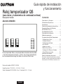
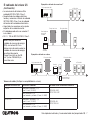
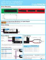
The QS Timeclock is a premier energy-saving astronomic timeclock for lights
and window treatments, which integrates seamlessly with the Lutron Energi
Savr Node components and QS window treatments.
Model Number: QSGR-TC-3S-WH
Rating: 120 –240 V~ 50 / 60 Hz 100 mA
Output: 24 V- 150 mA IEC PELV/NEC® Class 2 supply
English
®
Français Español Português Deutsch Italiano Nederlands 中文
Contents
Features and Functions ..................2
Line Voltage Wiring .....................3
Terminations ..........................3
Line Voltage Wiring Details ...............4
Overview of IEC PELV/NEC® Class 2 Wiring ..5
QS Link Wiring ........................6
Completing Installation ..................8
Programming Mode ....................9
Timeclock Operation
Setting Time and Date .................10
Setting Location .....................11
Setting Daylight Saving Time ...........11
Adding an Event .....................12
Deleting / Viewing an Event .............13
Setting / Viewing / Deleting a Holiday ......14
Copying / Deleting a Schedule ...........15
Troubleshooting .......................16
Warranty, Contact Information ...........18
For additional features and advanced functions,
see the complete installation and operation guide
(P/N 032383) at www.lutron.com

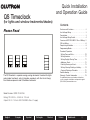
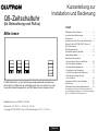
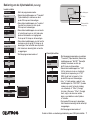
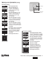
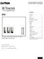
OK
12
3
4
5
6
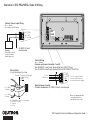
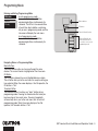
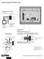
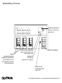
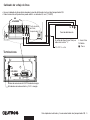
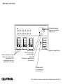
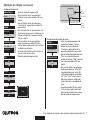
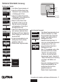
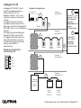
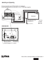
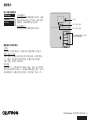
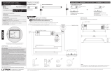
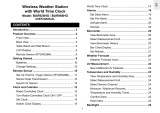
Info screen
Displays programming
functions
Program buttons
Shade (window treatment)
button groups
Preset and raise/lower
buttons with integral LEDs
(maximum of 3 button
groups)
Timeclock button
Displays current
timeclock info
OK button
Used for programming,
navigation
USB type mini B
For programming via PC
Features and Functions
QS Timeclock Quick Installation and Operation Guide 2
®

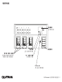
QS Timeclock Quick Installation and Operation Guide 3
®
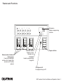
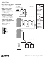
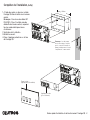
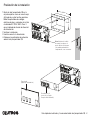
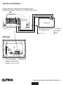
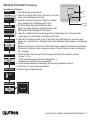
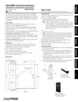
D1 D1 D2 D2
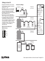
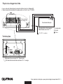
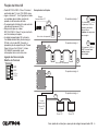
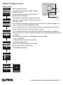
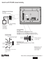
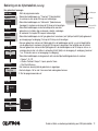
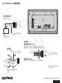
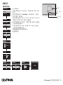
• Pull power wiring from distribution panel to QS Timeclock.
• Each line voltage terminal can accept one 12 AWG (4.0 mm²) wire.
Line Voltage Wiring
D1 D1 D2 D2
NOT USED
Rear of
QS Timeclock
1234
12
ABC
123456LN
Line voltage (Line / Hot)
is labeled L.
100–240 V~ only
Distribution Panel
1234
12
ABC
123456LN
Terminations
QS Communication link
Contact closure input and 24 V- power
NOT
USED
Input Power
L: Line / Hot
N: Neutral
: Ground

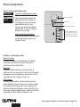
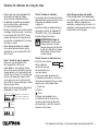
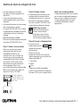
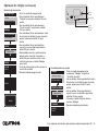
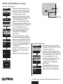
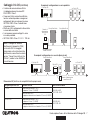
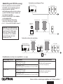
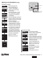
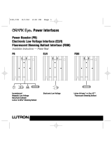
Line Voltage Wiring Details
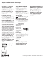
• Use properly certified cable for all line
voltage/mains cables.
• Proper short-circuit and overload
protection must be provided at the
distribution panel.
• Install in accordance with all local and
national electrical codes.
• IEC PELV/NEC® Class 2 terminals may
be temporarily unplugged for ease of
contact closure and control wiring.
• Notice: Risk of damage to unit. Do not
connect line voltage/mains cable to IEC
PELV/NEC® Class 2 terminals.
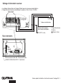
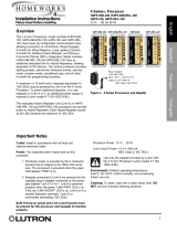
Step 1: Install wallbox. Mount a 3` in
(89 mm) deep 4-gang U.S. wallbox on a
dry, flat indoor surface that is accessible
and allows for system programming and
operation. Allow at least 4` in (110 mm)
clearance above and below the faceplate
to ensure proper heat dissipation. Allow
1 in (25 mm) for faceplate overhang on
all sides.
Note: 4-gang wallbox available from
Lutron; P/N 241400.
Step 2: Check wiring.
• Earth/ground terminal connection must
be made as shown in wiring diagrams
(see page 3).
• Follow all local and national electrical
codes when installing IEC PELV/NEC®
Class 2 wiring with line voltage/mains
wiring.
WARNING! Electric Shock hazard.
May result in Serious Injury or
Death. Always turn off circuit
breaker or remove main fuse from
power line before doing any work.
Step 3: Connect line voltage.
• Strip 9 in (8 mm) of
insulation off the line
voltage/mains cables in
the wallbox.
• Connect the line voltage/mains and
ground wires to the appropriate terminals
on the back of the timeclock.
L: Line / Hot
N: Neutral
: Ground
The recommended installation torque is
5.0 in∙lb (0.6 N∙m) for line voltage/mains
connections and 5.0 in∙lb (0.6 N∙m) for
the earth/ground connection.
Notice: Risk of damage to unit.
The QS Timeclock must be in stalled by
a qual i fied electrician in accordance with
all applica ble reg u la tions and building
codes. Im prop er wiring can result
in dam age to the timeclock or oth er
equipment.
QS Timeclock Quick Installation and Operation Guide 4
®
Faceplate overhangs
wallbox on all sides;
allow 1 in (25 mm)
4` in
(110 mm)
9 in
(8 mm)

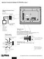
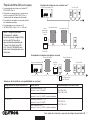
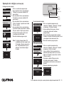
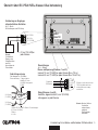
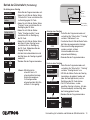
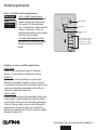
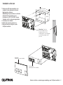
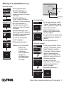
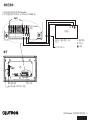
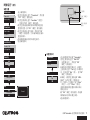
Contact Closure Input Wiring
24 V- 50 mA
For settings, see CCI Setup.
12
ABC
N H123456
1234
Note: Use appropriate wire
connecting devices as
specified by local codes.
Example:
Third-party contact
closure to enable /
disable timeclock
1: COM
2: 24 V-*
3: MUX
4: MUX
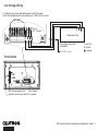
Control Wiring
24 V- 100 mA
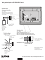
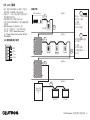
Overview of IEC PELV/NEC® Class 2 Wiring
18 AWG (1.0 mm
2
)
each terminal
A: CCI SIG
B: 24 V-
C: CCI COM
To other
QS devices
Data (terminals 3 and 4):
Twisted, shielded pair 22 AWG (0.5 mm
2
) each terminal
Common and power (terminals 1 and 2):
Two 18 AWG (1.0 mm
2
) each terminal (for link <500 ft/153 m)
Two 12 AWG (4.0 mm
2
) each terminal (for link 500–2000 ft/153–610 m)
* Do not connect terminal 2
between a QS Timeclock
and any other power supply.
QS Timeclock Quick Installation and Operation Guide 5
®
IEC PELV/NEC® Class 2 control wiring
(2) 18 AWG (1.0 mm
2
)
1: Common
2: 24 V-
Wiring Detail
For links 500–2000 ft (153–610 m)
4
3
2
1
Data link: (1) twisted, shielded pair
22 AWG (0.5 mm
2
)
3: MUX
4: MUX
(2) 12 AWG
(4.0 mm
2
)
(2) 12 AWG
(4.0 mm
2
)
NOT
USED

QS Timeclock Quick Installation and Operation Guide 6
®
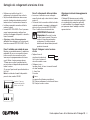
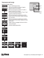
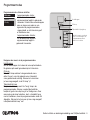
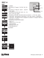
• Each IEC PELV/NEC® Class 2 terminal
accepts up to two 18 AWG (1.0 mm²)
wires.
• Connect the terminal 1, 3, and 4
connections to all control units,
wallstations, and control interfaces.
• Total length of control link must not
exceed 2000 ft (610 m).
• Do not allow IEC PELV/NEC® Class 2
wires to contact line/mains wires.
• The QS Timeclock provides 3 PDUs
(Power Draw Units) on the QS Link.
For more information, see Lutron
P/N 369405, “Power Draw Units on the
QS Link” at www.lutron.com
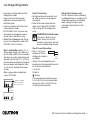
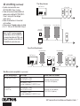
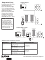
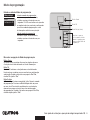
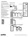
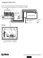
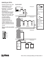
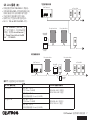
QS Communication Link
Terminal Detail
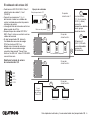
QS Link Wiring
D1 D1 D2 D2
_
MUX
24 V-
COM
LUTRON
LUTRON LUTRON LUTRON
Energi Savr Node
Sivoia QS
smart
power
panel
Sivoia QS
shade
Sivoia QS
shade
QS Timeclock
Wallstation
Wallstations
Connect all 4
terminals within a
power group:
1: Common
2: 24 V-
3 and 4: Data
Connect only 3
terminals between
power groups:
1: Common
3 and 4: Data
Do not connect
Terminal 2: 24 V-
A
B
A
A
A
B
B
B
Power Group 1
Power Group 2
Power Group 3
Power Group 4
Energi Savr Node
Wiring Example

• System communication uses
IEC PELV/NEC® Class 2 wiring.
• Follow all local and national electrical
codes when installing IEC PELV/NEC®
Class 2 wiring with line voltage/
mains wiring.
• Make all connections in the control
unit’s wallbox.
• Wiring can be T-tapped or daisy-chained.
• 24 V- 100 mA IEC PELV/NEC® Class 2.
QS Link Wiring (continued)
QS Timeclock Quick Installation and Operation Guide 7
®
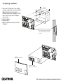
T-Tap Wiring Example
LUTRON LUTRONLUTRON LUTRON
LUTRON LUTRON LUTRON
LUTRON
LUTRON
LU
TRON
LUTRON LUTRON LUTRON
QS Timeclock
seeTouch QS
Sivoia QS
Shade
Sivoia QS
smart panel
Energi Savr Node
Energi Savr Node
LUTRON LUTRONLUTRON LUTRON
LUTRON LUTRON LUTRON
LUTRON
LUTRON
LU
TRON
LUTRON LUTRON LUTRON
Sivoia QS
smart panel
QS Timeclock
Sivoia QS
Shade
seeTouch QS
Daisy-Chain Wiring Example
Energi Savr Node
Energi Savr Node
Note: The QS Timeclock provides
3 power draw units on the QS link.
For more information on PDUs, see
“Power Draw Units on the QS Link”,
PN 369405 at www.lutron.com
Wire Sizes (check compatibility in your area)
QS Link Wiring Length Wire Gauge Lutron Cable Part Number
Less than 500 ft (153 m) Power (terminals 1 and 2)
1 pair 18 AWG (1.0 mm
2
) GRX-CBL-346S (non-plenum)
GRX-PCBL-346S (plenum)
Data (terminals 3 and 4)
1 twisted, shielded pair 22 AWG (0.5 mm
2
)
500 to 2000 ft
(153 to 610 m)
Power (terminals 1 and 2)
1 pair 12 AWG (4.0 mm
2
) GRX-CBL-46L (non-plenum)
GRX-PCBL-46L (plenum)
Data (terminals 3 and 4)
1 twisted, shielded pair 22 AWG (0.5 mm
2
)

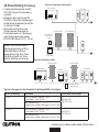
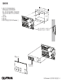
Completing Installation
1. Mount the QS Timeclock in the wallbox
as shown using the four screws pro vid ed.
Note: Follow all local and national
electrical codes when installing IEC PELV/
NEC® Class 2 wiring with line voltage/
mains wiring.
2. Verify installation.
3. Restore power.
4. Apply the protective overlay to the QS
Timeclock.
QS Timeclock Quick Installation and Operation Guide 8
Note: When tightening mounting
screws, make sure that the hinged
cover and faceplate will open fully,
as shown.
Wall
7.9 in
(200 mm)
3.5 in
(87 mm)
3.75 in
(95 mm)
Protective overlay
(apply after installation)
Faceplate
(apply after installation)
®

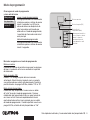
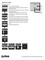
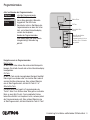
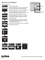
Entering and Exiting Programming Mode
To enter programming mode:
Press and hold the top and bottom
programming buttons simultaneously for
3 seconds. The LEDs in the scene buttons
will scroll from top to bottom, confirming
that you are in programming mode, and the
info screen will display the main menu.
To exit programming mode:
Press and hold the top and bottom
programming buttons simultaneously for
3 seconds.
Navigating Menus in Programming Mode
Master Buttons
The Master buttons allow you to move through the menu
choices. The current choice is highlighted on the info screen.
OK Button
The OK button chooses the current highlighted menu choice.
This will either take you to the next menu or accept a setting you
have selected. When the screen displays a Yes / No question, the
OK button is “Yes”.
Timeclock Button
The timeclock button functions as a “back” button during
programming mode. Pressing the timeclock button takes you
back one step in the current menu. Pressing it repeatedly
will eventually return you to the main menu, but will not exit
programming mode. When the screen displays a Yes / No
question, the Timeclock button is “No”.
Programming Mode
Main menu
CCI setup
Timeclock
QS Timeclock Quick Installation and Operation Guide 9
®
OK
12
3
4
5
6
Press and hold the top
and bottom buttons for
3 seconds to enter or exit
programming mode
Master buttons
OK button
Timeclock (back) button

QS Timeclock Quick Installation and Operation Guide 10
®
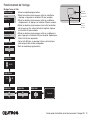
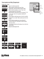
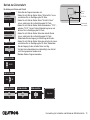
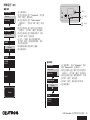
Timeclock Operation
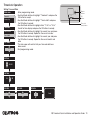
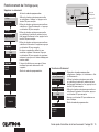
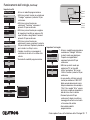
Setting Time and Date
1. Enter programming mode.
2. Use the Master buttons to highlight “Timeclock” and press the
OK button to accept.
3. Use the Master buttons to highlight “Time & date” and press
the OK button to accept.
4. Use the Master buttons to highlight either “12 Hr” or “24 Hr”
format for time display and press the OK button to accept.
5. Use the Master buttons to highlight the current hour and press
the OK button to accept. Repeat for the current minutes.
6. Use the Master buttons to highlight the current year and press
the OK button to accept. Repeat for the current month and
date.
7. The info screen will confirm that your time and date have
been saved.
8. Exit programming mode.
Main menu
Timeclock
Scene setup
Timeclock
End afterhours
Time & date
Set time
: 00 AM
08
Timeclock
Set date
: 00
2009
Set date
Set format
12 Hr
March
Set date
17
Set time
08 : AM
30
Saved
OK
1 2 3 4 5 6
Master
buttons
OK
button
Timeclock
(back) button

QS Timeclock Quick Installation and Operation Guide 11
®
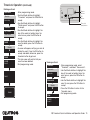
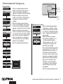
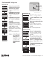
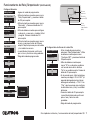
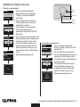
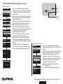
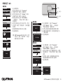
Setting Daylight Saving Time
1. Enter programming mode and
select “Timeclock”. Use the Master
buttons to highlight “Set DST” and
press the OK button to accept.
2. Use the Master buttons to highlight
“YES” if your location observes
daylight saving time, or “NO” if it
does not. Press the OK button to
accept.
3. If yes, use the Master buttons to
choose either “USA 2007” (the
second Sunday in March to the first
Sunday in November), or “Other.”
For “Other,” follow the screens to
set start and end dates and amount
of time.
4. Press the OK button to accept. The
info screen will confirm that your
time and date have been saved.
5. Exit programming mode.
Timeclock Operation (continued)
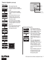
Setting Location
1. Enter programming mode.
2. Use the Master buttons to highlight
“Timeclock” and press the OK button to
accept.
3. Use the Master buttons to highlight
“Location” and press the OK button to
accept.
4. Use the Master buttons to set your
location by either country and city
or latitude and longitude. Press the
OK button to accept.
5. Use the Master buttons to highlight
the country and press the OK button
to accept. Repeat for the state and
closest city.
6. The info screen will confirm that your
time and date have been saved.
7. Exit programming mode.
Main menu
Timeclock
Scene setup
Timeclock
Time & date
Location
Location by
Lat/Longitude
Country, City
Timeclock
State
Pennsylvania
City
Philadelphia
Country
08 : 00
USA
Timeclock
Location
Set DST
DST
: 00
Yes
Saved
OK
1 2 3 4 5 6
Master
buttons
OK
button
Timeclock
(back) button

QS Timeclock Quick Installation and Operation Guide 12
®
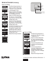
Timeclock Operation (continued)
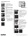
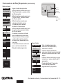
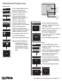
Adding an Event
1. Enter programming mode.
2. Use the Master buttons to highlight “Timeclock” and press the OK
button to accept.
3. Use the Master buttons to highlight “Add events” and press the
OK button to accept.
4. Use the Master buttons to highlight the recurrence for this event:
day of the week, holiday, weekdays or weekends. Press the OK
button to accept.
5. Use the Master buttons to highlight the type of the event (fixed time of day or a relative time to sunrise or
sunset). Press the OK button to accept.
6. For a fixed-time event, use the Master buttons to highlight the hour for your event to begin; press the OK
button to accept. Repeat for the minutes.
For a relative-time event, use the Master buttons and the OK button to set the hour, then the minutes relative
to sunrise or sunset (maximum of 1 hour, 59 minutes before or after sunrise or sunset).
7. Use the Master buttons to highlight the desired action for the timeclock event:
• Scenes 1-16, Off
• Window Treatment Groups 1-3 open, preset, or close
• Start/End Afterhours
8. The info screen will confirm that your event has been saved.
9. Repeat steps 4 through 9 for additional events.
10. Exit programming mode.
Main menu
Timeclock
Scene setup
Timeclock
Add events
Monday
Add events
Time of day
Add events
Scene
Scene 1
Set time
: 00 AM
08
Saved
Timeclock
View events
Add events
OK
1 2 3 4 5 6
Master
buttons
OK
button
Timeclock
(back) button

QS Timeclock Quick Installation and Operation Guide 13
®
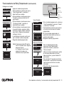
Timeclock Operation (continued)
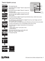
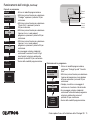
Deleting an Event
1. Enter programming mode.
2. Use the Master buttons to highlight
“Timeclock” and press the OK button to
accept.
3. Use the Master buttons to highlight
“Delete events” and press the OK button
to accept.
4. Use the Master buttons to highlight the
day of the week (or holiday) when the
event occurs; press the OK button to
accept.
5. Use the Master buttons to highlight the
event to delete; press the OK button to
accept.
6. A screen will appear, verifying you wish to
delete the event. Press the OK button to
accept and delete; otherwise, press the
timeclock button to go back.
7. The info screen will confirm that your
event has been deleted.
8. Exit programming mode.
Main menu
Timeclock
Scene setup
Timeclock
Copy schedule
Timeclock
Delete?
Delete
8:00 AM
Scene 5
Delete
Monday
01/03
Viewing an Event
1. Enter programming mode, select
“Timeclock,” and select “View events”.
2. Use the Master buttons to highlight the
day of the week (or holiday) when the
event occurs; press the OK button to
accept.
3. Use the Master buttons to highlight the
event to view; press the OK button to
accept.
4. Press the OK button to return to the
Timeclock menu.
5. Exit programming mode.
Timeclock
Delete events
Add events
View events
Monday
View
8:00 AM
Scene 5
View events
Monday
1/3
R
Delete events
Deleted
OK
12
3
4
5
6910
11 12
13
14
7
815
16
9-16
1-8
Master
buttons
OK
button
Timeclock
(back) button

QS Timeclock Quick Installation and Operation Guide 14
®
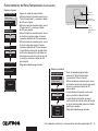
Timeclock Operation (continued)
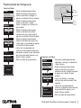
Setting a Holiday
1. Enter programming mode.
2. Use the Master buttons to highlight
“Timeclock” and press the OK button
to accept.
3. Use the Master buttons to highlight
“Holiday” and press the OK button to
accept.
4. Use the Master buttons to highlight
“Set holiday” and press the OK button
to accept.
5. Use the Master buttons to highlight
the month of the holiday and press the
OK button to accept. Repeat for the
date.
6. The info screen will confirm that your
holiday has been set.
7. Exit programming mode.
Note: The QS Timeclock supports up
to 25 unique holidays. Follow the
steps in “Adding an Event” to
add Holiday timeclock events.
Timeclock
Delete schedule
Holiday
Add event
View holiday
Set holiday
Holiday
Set holiday
1/25
1
Feb
Monday
Set holiday
1/25
Feb
14
Deleting a Holiday
1. Enter programming mode, select
“Timeclock,” select “Holiday,” and
select “Delete holiday”.
2. Use the Master buttons to highlight the
holiday you wish to delete (or delete all
holidays) and press the OK button to
accept.
3. Press the OK button to delete the
selected holiday. The info screen
will confirm that your holiday has
been deleted.
4. Exit programming mode.
Holiday
View holiday
Delete holiday
Monday
Saved
Deleted
Viewing a Holiday
1. Enter programming mode, select
“Timeclock,” select “Holiday,” and select
“View holiday”.
2. Use the Master buttons to scroll through
the dates of the programmed holidays.
3. If no holidays are programmed, the
info screen will display a screen
informing you.
4. Exit programming mode.
View Holiday
1/25
Feb 14
Monday
No Holidays
OR
Delete holiday
1/2
Feb 14
Delete holiday
1/2
Delete?
OK
1 2 3 4 5 6
Master
buttons
OK
button
Timeclock
(back) button

QS Timeclock Quick Installation and Operation Guide 15
®
Timeclock Operation (continued)
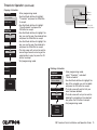
Copying a Schedule
1. Enter programming mode.
2. Use the Master buttons to highlight
“Timeclock” and press the OK button
to accept.
3. Use the Master buttons to highlight
“Copy Schedule” and press the
OK button to accept.
4. Use the Master buttons to highlight the
day you want to copy the schedule from
and press the OK button to accept.
5. Use the Master buttons to highlight the
day you want to copy the schedule to
and press the OK button to accept.
6. The info screen will ask you to confirm
overwriting all events occurring on the
selected day to copy to; press the OK
button to accept.
7. Exit programming mode.
Timeclock
Delete schedule
Delete events
Copy schedule
Copy from
Monday
Monday
Timeclock
Overwrite
all events?
Deleting a Schedule
1. Enter programming mode,
select “Timeclock,” and select
“Delete schedule”.
2. Use the Master buttons to highlight the
day of the schedule you wish to delete
and press the OK button to accept.
3. The info screen will confirm that your
event has been deleted.
4. The info screen will ask you to confirm
deleting the schedule on the selected
day; press the OK button to accept.
5. Exit programming mode.
Timeclock
Delete events
Delete schedule
Saved
Delete
Sunday
schedule?
Monday
Copy to
Tuesday
Monday
Delete schedule
Sunday
OK
1 2 3 4 5 6
Master
buttons
OK
button
Timeclock
(back) button

QS Timeclock Quick Installation and Operation Guide 16
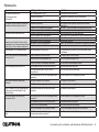
®
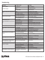
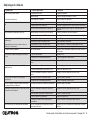
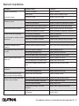
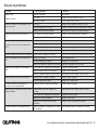
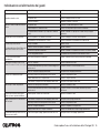
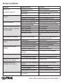
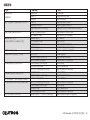
Symptom Possible Causes Remedy
Unit does not power up
Circuit breaker is tripping
Circuit Breaker is off Switch circuit breaker on
Miswire Verify wiring to unit and loads
System short circuited Find and correct shorts
Integral (direct-wired) contact closure input does not
work
Miswire Check wiring on contact closure input
Input CCI signal is not received Verify the input device is operating properly
Unit is in wrong CCI mode and/or type Change to correct CCI mode and/or type for your application
QS devices on link are not working Miswire or loose connection on QS link Verify QS link wiring to all devices
QS device programming is incorrect Verify the functionality and programming on the QS devices
Timeclock events do not occur
Sunrise or sunset events do not occur at the correct
time
Timeclock is disabled Enable the timeclock
Time/date is not set correctly Set the time/date
Location is not set correctly Set the latitude and longitude of the unit’s location
Holiday schedule is in effect Normal schedule will resume when the holiday ends
Security lockout from programming mode Security password set incorrectly Call Lutron Technical Support to reset password
Window treatment EDU (electronic drive unit) will not
move
EDU is not powered Connect power to EDU
Window treatment fabric is caught on something Check and unbind window treatment fabric
EDU is not assigned to a shade button group Assign the EDU to a shade button group
Shade button group will not control any window
treatment
All limits are set to the same height Verify limit settings
Communications link is not wired to the EDU Check and wire the EDU link
EDU has been unassigned from shade button group Reassign the EDU to the shade button group
Window treatment EDU does not fully open or fully
close
Limits have been set incorrectly Set limits correctly
Window treatment fabric is caught on something Check and unbind window treatment fabric
Window treatment moves in the opposite direction
when raise/lower buttons are pushed
Open and close limits have been reversed Set limits correctly
Shade button group does not operate all the window
treatments it is assigned to
EDU has been unassigned from shade button group Reassign the EDU to the shade button group
All limits are set to the same height Verify limit settings
EDU is not wired correctly Check and rewire EDU
Shade button group is not wired correctly Check and rewire shade button group
Window treatments in a room move on their own EDUs are assigned to a shade button group in
another room
Reassign the EDU to the correct shade button group
Troubleshooting

QS Timeclock Quick Installation and Operation Guide 17
®
Notes

®
Warranty
For full warranty information, see www.lutron.com/TechnicalDocumentLibrary/Warranty_CommercialSystems.pdf
®
Lutron, Lutron, Energi Savr Node, GRAFIK Eye, seeTouch, and Sivoia are trademarks or registered trademarks of Lutron Electronics Co., Inc. in
the US and/or other countries.
NEC is a registered trademark of the National Fire Protection Association, Quincy, Massachusetts.
© 2011–2019 Lutron Electronics Co., Inc.
Contact Information
Internet: www.lutron.com
E-mail: product@lutron.com
WORLD HEADQUARTERS
USA
Lutron Electronics Co., Inc.
7200 Suter Road
Coopersburg, PA 18036-1299
TEL +1.610.282.3800
FAX +1.610.282.1243
Customer Assistance:
1.844.LUTRON1
www.lutron.com/support
North and South America
Customer Assistance
USA, Canada, Caribbean:
1.844.LUTRON1 (1.844.588.7661)
Mexico: +1.888.235.2910
Central/South America: +1.610.282.6701
EUROPEAN HEADQUARTERS
United Kingdom
Lutron EA Limited
125 Finsbury Pavement
4th floor, London EC2A 1NQ
United Kingdom
TEL: +44.(0)20.7702.0657
FAX: +44.(0)20.7480.6899
FREEPHONE (UK): 0800.282.107
Customer Assistance:
+44.(0)20.7680.4481
ASIAN HEADQUARTERS
Singapore
Lutron GL Ltd.
390 Havelock Road
#07-04 King’s Centre
Singapore 169662
TEL: +65.6220.4666
FAX: +65.6220.4333
Customer Assistance: 800.120.4491
lutronsea@lutron.com
Asia Customer Assistance
Northern China: 10.800.712.1536
Southern China: 10.800.120.1536
Hong Kong: 800.901.849
Indonesia: 001.803.011.3994
Japan: +81.3.5575.8411
Macau: 0800.401
Singapore: 800.120.4491
Taiwan: 00.801.137.737
Thailand: 001.800.120.665853
Other countries: +65.6220.4666
Lutron Electronics Co., Inc.
P/N 032535 Rev. A 03/2019

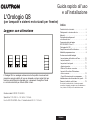
L'horloge QS
(pour éclairage et traitements de fenêtres/stores)
Guide rapide d’installation
et de fonctionnement
À lire attentivement
L'horloge QS est une horloge astronomique de premier ordre pour
l'économie d'énergie des éclairages et des stores et rideaux, qui s'intègre
harmonieusement avec les composants de Lutron Energi Savr Node et les
stores et rideaux QS.
Numéro de Modèle : QSGR-TC-3S-WH
Valeurs nominales : 120 –240 V~ 50 / 60 Hz 100 mA
Sortie : 24 V- 150 mA IEC PELV/NEC® Class 2 alimentation
Contenu
Caractéristiques et fonctions .............2
Câblage d’alimentation secteur ...........3
Raccordements ........................3
Détails du câblage d’alimentation secteur ...4
Aperçu du câblage IEC PELV/NEC® Class 2 . 5
Câblage du bus QS .....................6
Compléter de l’installation ...............8
Mode de programmation ................9
Fonctionnement de l'horloge
Réglage Temps et Date ................10
Réglage Endroit ......................11
Réglage Heure Avancée ...............11
Ajouter un Événement .................12
Supprimer / Visualiser un événement ......13
Régler / Visualiser / Supprimer
un Jour férié ........................14
Copier / Supprimer une Cédule ..........15
Dépistage de défauts ..................16
Garantie, Information de contact .........18
Pour connaître les fonctionnalités supplémentaires et
les fonctions avancées, consultez le guide complet
d’installation et d’utilisation (no de pièce032383) sur
www.lutron.com
®
Français

Guide rapide d’installation et de fonctionnement l'horloge QS 2
®
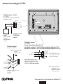
OK
12
3
4
5
6
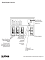
Écran d’information
Affiche les fonctions de
programmation
Touches programme
Groupes de bouton pour
Stores (traitements de
fenêtres)
Boutons de rappel et
d’ajustement de niveau avec
DEL intégrées (maximum de
3 groupes de boutons)
Bouton d’horloge
Affiche l’information
courante de l’horloge
Bouton OK
Utilisée pour la
programmation,
navigation
USB type mini B
Pour programmer à l’aide
d’un PC
Caractéristiques et fonctions
A página está carregando...
A página está carregando...
A página está carregando...
A página está carregando...
A página está carregando...
A página está carregando...
A página está carregando...
A página está carregando...
A página está carregando...
A página está carregando...
A página está carregando...
A página está carregando...
A página está carregando...
A página está carregando...
A página está carregando...
A página está carregando...
A página está carregando...
A página está carregando...
A página está carregando...
A página está carregando...
A página está carregando...
A página está carregando...
A página está carregando...
A página está carregando...
A página está carregando...
A página está carregando...
A página está carregando...
A página está carregando...
A página está carregando...
A página está carregando...
A página está carregando...
A página está carregando...
A página está carregando...
A página está carregando...
A página está carregando...
A página está carregando...
A página está carregando...
A página está carregando...
A página está carregando...
A página está carregando...
A página está carregando...
A página está carregando...
A página está carregando...
A página está carregando...
A página está carregando...
A página está carregando...
A página está carregando...
A página está carregando...
A página está carregando...
A página está carregando...
A página está carregando...
A página está carregando...
A página está carregando...
A página está carregando...
A página está carregando...
A página está carregando...
A página está carregando...
A página está carregando...
A página está carregando...
A página está carregando...
A página está carregando...
A página está carregando...
A página está carregando...
A página está carregando...
A página está carregando...
A página está carregando...
A página está carregando...
A página está carregando...
A página está carregando...
A página está carregando...
A página está carregando...
A página está carregando...
A página está carregando...
A página está carregando...
A página está carregando...
A página está carregando...
A página está carregando...
A página está carregando...
A página está carregando...
A página está carregando...
A página está carregando...
A página está carregando...
A página está carregando...
A página está carregando...
A página está carregando...
A página está carregando...
A página está carregando...
A página está carregando...
A página está carregando...
A página está carregando...
A página está carregando...
A página está carregando...
A página está carregando...
A página está carregando...
A página está carregando...
A página está carregando...
A página está carregando...
A página está carregando...
A página está carregando...
A página está carregando...
A página está carregando...
A página está carregando...
A página está carregando...
A página está carregando...
A página está carregando...
A página está carregando...
A página está carregando...
A página está carregando...
A página está carregando...
A página está carregando...
A página está carregando...
A página está carregando...
A página está carregando...
A página está carregando...
A página está carregando...
A página está carregando...
A página está carregando...
A página está carregando...
A página está carregando...
A página está carregando...
A página está carregando...
A página está carregando...
A página está carregando...
A página está carregando...
-
 1
1
-
 2
2
-
 3
3
-
 4
4
-
 5
5
-
 6
6
-
 7
7
-
 8
8
-
 9
9
-
 10
10
-
 11
11
-
 12
12
-
 13
13
-
 14
14
-
 15
15
-
 16
16
-
 17
17
-
 18
18
-
 19
19
-
 20
20
-
 21
21
-
 22
22
-
 23
23
-
 24
24
-
 25
25
-
 26
26
-
 27
27
-
 28
28
-
 29
29
-
 30
30
-
 31
31
-
 32
32
-
 33
33
-
 34
34
-
 35
35
-
 36
36
-
 37
37
-
 38
38
-
 39
39
-
 40
40
-
 41
41
-
 42
42
-
 43
43
-
 44
44
-
 45
45
-
 46
46
-
 47
47
-
 48
48
-
 49
49
-
 50
50
-
 51
51
-
 52
52
-
 53
53
-
 54
54
-
 55
55
-
 56
56
-
 57
57
-
 58
58
-
 59
59
-
 60
60
-
 61
61
-
 62
62
-
 63
63
-
 64
64
-
 65
65
-
 66
66
-
 67
67
-
 68
68
-
 69
69
-
 70
70
-
 71
71
-
 72
72
-
 73
73
-
 74
74
-
 75
75
-
 76
76
-
 77
77
-
 78
78
-
 79
79
-
 80
80
-
 81
81
-
 82
82
-
 83
83
-
 84
84
-
 85
85
-
 86
86
-
 87
87
-
 88
88
-
 89
89
-
 90
90
-
 91
91
-
 92
92
-
 93
93
-
 94
94
-
 95
95
-
 96
96
-
 97
97
-
 98
98
-
 99
99
-
 100
100
-
 101
101
-
 102
102
-
 103
103
-
 104
104
-
 105
105
-
 106
106
-
 107
107
-
 108
108
-
 109
109
-
 110
110
-
 111
111
-
 112
112
-
 113
113
-
 114
114
-
 115
115
-
 116
116
-
 117
117
-
 118
118
-
 119
119
-
 120
120
-
 121
121
-
 122
122
-
 123
123
-
 124
124
-
 125
125
-
 126
126
-
 127
127
-
 128
128
-
 129
129
-
 130
130
-
 131
131
-
 132
132
-
 133
133
-
 134
134
-
 135
135
-
 136
136
-
 137
137
-
 138
138
-
 139
139
-
 140
140
-
 141
141
-
 142
142
-
 143
143
-
 144
144


Lutron Electronics QS Timeclock Quick Installation And Operation Manual
- Tipo
- Quick Installation And Operation Manual
- Este manual também é adequado para
em outras línguas
- español: Lutron Electronics QS Timeclock
- français: Lutron Electronics QS Timeclock
- italiano: Lutron Electronics QS Timeclock
- English: Lutron Electronics QS Timeclock
- Nederlands: Lutron Electronics QS Timeclock
- Deutsch: Lutron Electronics QS Timeclock
Artigos relacionados
-
 Lutron Electronics QS Timeclock Instruções de operação
-
 Lutron Electronics seeTouch QSWS2-3BRL Guia de instalação
-
 Lutron Electronics HOMEWORKS H4P5-HRL-120 Installation Instructions Manual
-
Lutron Electronics GRAFIK 6000 Installation Instructions Manual
-
 Lutron Electronics Hi-lume Premier 0.1 Installation Best Practices Manual
-
 Lutron Electronics DFC-OEM-DBI Guick Start Manual
-
Lutron Homeworks HRP5-120 Installation Instructions Manual
-
 Lutron Electronics QSE-CI-DMX Installation And Operation Instructions Manual
-
 Lutron Electronics Grafik Eye PB Installation Instructions Manual
-


Outros documentos
-
Lutron QSN-2ECO-120-D Guia de instalação
-
-
Lutron Roller 100 Manual do usuário
-
 Oregon Scientific BAR966HG Manual do usuário
-
-
Orbis MODUL LOG Manual do usuário
-
WEG SRW01 Guia de usuario
-
Hunter NODE-BT Guia de instalação
-
ABB twa-2 Manual do usuário
-
AMX CCD-W6BRL Guia de instalação
