A página está carregando...

1
English Español Français Português
Please Read Before Installing
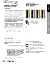
RF Processor
HRP5-120
Installation Instructions
Setup: RF Processors will not function until they are
addressed and programmed. See the HomeWorks
Illumination Software online help.
Overview
HomeWorks RF Processors comprise the major
communication hub of a HomeWorks radio frequency
system. Each RF Processor will support up to 32 RF
Keypads and up to 64 RF Dimmers or RF Switches.
Each RF Processor covers approximately 2500 ft
2
(232 m
2
) of living space.
Up to four (4) Hybrid Repeaters may be used with each
RF Processor to extend the communications range of the
system.
A maximum of 16 HomeWorks Processors may be
connected together in a system.
Important Notes
Codes: Install in accordance with all local and
national electrical codes.
Power: Use only the adapter provided by Lutron with
the RF Processor (Lutron model # T120-15DC-9-BL).
Caution - Using an adapter not rated for the
following specifications could damage the
processor and possibly overheat the adapter.
Environment: Ambient operating temperature:
32–104 °F (0–40 °C), 0–90% humidity, non-condensing.
Indoor use only.
Cleaning: To clean, wipe with a clean damp cloth. DO
NOT use any chemical solutions. DO NOT paint the RF
Processor.
Mounting: DO NOT ground the RF Processor. DO
NOT mount the RF Processor in a metal enclosure.
RF Device Placement: RF devices that are to be
controlled by the RF Processor must be located within
30 ft (9 m) of the RF Processor or a Hybrid Repeater.
The range and performance of RF devices in a
HomeWorks system is highly dependent on a variety of
complex factors such as:
• Distance between RF devices
• Geometry of the home
• Construction of walls separating RF devices
Range and performance can be adversely affected by:
• Mounting in a metal enclosure
• Mounting within 3 ft (1 m) of other RF devices
HRP5-120
Plug-in Adapter
T120-15DC-9-BL
Input: 100 – 240 V
~ 50 / 60 Hz 500 mA
Output: 15 V
- 1.2 A
NECR Class 2; IEC PELV
043506 Rev. A
10/2018

2
EnglishEspañolFrançaisPortuguês
6. Connect Serial Link (if applicable). Connect a standard
DB9 male connector to the Link 3 or 7 RS-232 connector
on the RF Processor for system programming or
communications with other equipment. A cable with all
9 pins straight through (not a null modem) is required for
programming the system via the serial link using a laptop. If
the RF Processor is connected to a modem, a null modem
adapter is needed between the processor and the attached
modem.
7. Connect Ethernet Link (if applicable). Connect a
standard RJ45 connector to the Link 9 Ethernet jack on the
processor for system programming or communications with
other equipment. A crossover cable is required for a direct
connection to a computer. If plugging in to a
network, a standard cable is used (see Processor Board
Connections on page 7). The orange LED (ACT) will
illuminate when there are any Ethernet signals being
transmitted or received on Link 9. The green LED (CON) will
illuminate when the Link 9 is connected to a hub/switch/
router or a computer. For help configuring a laptop to talk
to the processor, see Help in the HomeWorks Illumination
Software.
8. Connect Hybrid Repeater Link (if applicable). For
Hybrid Repeaters that control wireless devices, connect
the communication wires to Link 8 as configured in the
HomeWorks Illumination Software. Important: Use only the
blue terminal block connector that is provided with the RF
Processor. Link 8 does not provide power for the Hybrid
Repeaters. The Hybrid Repeaters must be powered by the
plug-in adapters that are provided with the repeaters.
9. Connect external input closures (if applicable). The
processor accepts three low-voltage dry contact closures.
Important: Use only the blue terminal block connector that
is provided with the RF Processor.
When using the input closures: Verify compatibility of
external devices. The input closures are intended for use
with devices that provide dry contact closures. The inputs
may be used with ground-referenced, solid-state closures
if the closures have an on-state saturation voltage of less
than 2 V- and an off-state leakage of less than 50 μA.
Dry contact or solid-state closures must be capable of
switching 15 V- at 10 mA. The closures must stay in the
closed or open states for at least 40 msec in order to be
recognized by the processor. If there is any question as to
whether the contact closure device is compatible with these
specifications, contact the manufacturer of that device.
The Contact Closure Input Status LEDs will illuminate when
a contact closure is closed on the corresponding input.
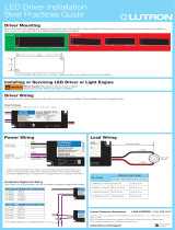
Installation
1. Find a suitable location for the RF Processor. Place
the RF Processor in a convenient and accessible
location. See RF Coverage Diagrams on page 8 and 9.
2. Mount the RF Processor. Mount RF Processor to wall
using the appropriate mounting hardware provided (see
Mounting Diagram). Orient the processor’s antenna for
optimal performance. For most installations, the antenna
should be oriented vertically.
Note: DO NOT ground the RF Processor. DO
NOT mount the RF Processor in a metal
enclosure.
3. Connect Inter-processor Link (if applicable). The
inter-processor link is used for communication between
multiple HomeWorks processors. Connect control wiring
to the Inter-Processor link (4-position terminal block), if
required. Do not connect the +15 V terminal (terminal 2).
If this processor is to be the first or last processor in the
daisy chain, attach one of the LT-1 link terminators
provided across the MUX and _ (terminals 3 and 4).
(See Low-Voltage (Class 2/PELV) Wiring Diagram, page
5). If LT-1s are unavailable, a 1/2 W resistor between 100
and 150 Ohms may be placed across terminals 3 and 4 to
provide termination. Important: Use only the blue
terminal block connector that is provided with the
RF Processor.
4. Apply power to the RF Processor.
The RF Processor has battery-backed memory and
timeclock devices. The battery provides power to these
devices during power outages and other temporary power
interruptions. In vacation homes and other residences
which are not continuously occupied, the RF processor
MUST be powered by a circuit that is never turned off even
when the residence is unoccupied.
5. Address the RF Processor. Use the RF Processor
display to set address.
Verify LED lights
when powered
Plug in power
cord and
adapter

3
English Español Français Português
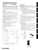
Port Cover Removal and Installation
The Port Cover can be removed for access to the
Initialize Button, Configuration DIP Switches, and
Diagnostic LEDs. The cover is removed by gently pulling
up on the front edge to disengage the snaps. Replace
the cover by inserting the two tabs on the back of the
cover into the slots on the processor. Gently press
down on the front edge to engage the snaps.
Slots
Tab
Tab
Press
Down
11.54 in
(293 mm)
8 in
(203 mm)
1.25 in
(32 mm)
6.16 in
(157 mm)
6.7 in
(170 mm)
0.70 in
(18 mm)
Front View
(Port Cover attached)
Side View
5.77 in
(147 mm)
1.77 in
(45 mm)
Dimensions
7 in
(178 mm)

4
EnglishEspañolFrançaisPortuguês
Contact Closure Wiring Diagram
Class 2/PELV wiring connections
from customer supplied contact
closure devices. (See Installation
step 9 on page 2.)
OK
Closure 3
Closure 2
Closure 1
Common
#
OK
*
Mounting Screw
Mounting Screw
Optional Mounting Screw
Mounting Diagram
Included:
Drywall Anchors (3)
Mounting Screws (3)
Masonry Anchors (3)
Mounting Screws (3)
Wall Anchors

5
English Español Français Português
Low-Voltage (Class 2/PELV) Wiring Diagram
LT-1 Link
Terminator
LT-1 Link
Terminator
Wiring Detail
LT-1 Link
Terminator
LT-1 Link
Terminator
Wiring Detail
4-Series
Processor
RF Processor
Pin 1 - 1 18 AWG (1.0 mm
2
)
Pins 3 & 4 - 1 pair 22-18 AWG (0.5 - 1.0 mm
2
)
twisted/shielded for data
Pin 2 is not connected
1000 ft (305 m) maximum total wire run distance
8-Series
Processor

6
EnglishEspañolFrançaisPortuguês
OK
Operation and LEDs
Home Key
Display Power
LED
1. Home Key: Returns the user to the Home Screen.
2. Menu Navigation Keys: Used to navigate the various
menus and screens for the processor.
3. Ethernet Link 9 Activity LEDs: The orange LED will
illuminate when there are any Ethernet signals being
transmitted or received on Link 9. The green LED will
illuminate when the ethernet port is connected to a hub/
switch/router or a PC.
4. RS-232 Link 7 Activity LEDs: The LEDs will illuminate
when there are any RS-232 signals being transmitted
(TX LED) or received (RX LED) on Link 7.
5. RS-232 Link 3 Activity LEDs: The LEDs will illuminate
when there are any RS-232 signals being transmitted
(TX LED) or received (RX LED) on Link 3.
6. Inter-Processor Link Activity LEDs: The LEDs will
illuminate when there are any processor communication
signals being transmitted (TX LED) or received (RX LED) on
Link 2.
LCD Display
7. Contact Closure Input Status LEDs: The LEDs will
each illuminate when a contact closure is closed on the
corresponding input.
8. Hybrid Repeater Link 8 Activity LEDs: The LEDs will
illuminate when there are any wired signals being
transmitted (TX LED) or received (RX LED) on Link 8.
9. RF Link Activity LEDs: The LEDs will illuminate when
there are any RF signals being transmitted (TX LED) or
received (RX LED) on that link.
10. Power In LED: This LED illuminates when power from the
adapter is present at the Power Input Jack.
11. LCD Display: Displays programming and diagnostic
information. The LCD Display will shut off after 45 minutes
of inactivity. To restore the display, simply press any key.
12. Display Power LED: This LED will illuminate when the
LCD Display has power.
1
11
12
Menu
Navigation
Keys
2
3
4
RS-232 Link 7
Activity LEDs
Ethernet
Link 9 Activity
LEDs
RS-232 Link 3
Activity LEDs
Contact
Closure Input
Status LEDs
Inter-Processor
Link 2 Activity
LEDs
Hybrid Repeater
Link 8 Activity
LEDs
Power In
LED
RF Activity
LEDs
5
6 8
97
10

7
English Español Français Português
Processor Board Connections
1. RS-232 Port (Link 3 and 7): Standard 9-Pin male
connectors for connecting to a computer for programming,
to a modem for remote programming, or to an external
control system (A/V system, HVAC, etc.).
2. Ethernet Jack (Link 9): Standard 8-Pin RJ-45 jack for
connecting the processor to an Ethernet Hub/Switch, to a
laptop computer for remote programming, or to an
external control system (A/V system, HVAC, etc.).
3. Inter-Processor Link (Link 2): Allows up to 16
processors (both RF and Wired) to be connected together.
4. Contact Closure Inputs: Connection for 3 dry contact
closures plus common.
5. Hybrid Repeater Link (Link 8): Allows connection of
Hybrid Repeaters.
6. Configuration DIP Switches: All DIP switches should
be placed in the OFF (left) position for normal operation.
The HomeWorks utility will prompt the programmer if any
subsequent changes to the DIP switches are required.
7. Power Input Jack: Input jack for the 15 V- adapter.
Center pin is positive.
8. Initialize Button: Used to reset the processor.
Ethernet Port (Link 9)
RS-232 Ports
(Links 3 and 7)
Inter-Processor
Link (Link 2)
Hybrid Repeater
Link (Link 8)
Power Input Jack
Contact
Closure Inputs
Configuration DIP Switches
Initialize Button
1
2
3
4 NC
5 NC
6
7 NC
8 NC
1
2
3
4
5
6
7
8
NC
NC
NC
NC
Crossover Cable Configuration
A crossover cable is used when
connecting the processor to a laptop
or other non-hub device (a/v systems,
HVAC, etc.)
1
2
3
4
5
6
7
8
OFF - Left
ON - Right
Example: Setting Switch #6 ON.
PIN Name Description
1 DCD Data Carrier Detect
2 TXD Transmit Data
3 RXD Receive Data
4 DSR Data Set Ready
5 GND Ground
6 DTR Data Terminal Ready
7 CTS Clear to Send
8 RTS Request to Send
9 RI Ring Indicate
PIN Processor Ethernet Hub/Switch
1 Transmit +ve Receive +ve
2 Transmit -ve Receive -ve
3 Receive +ve Transmit +ve
4 No Connection No Connection
5 No Connection No Connection
6 Receive -ve Transmit -ve
7 No Connection No Connection
8 No Connection No Connection
DIP Switch OFF ON
1 Normal Mode Boot Mode
2 User-Configured
Baud Rate
9600 Baud
3 Normal Mode Not Used
4 Normal Mode Not Used
5 Normal Mode Not Used
6 Normal Mode Not Used

*
123
4
8
EnglishEspañolFrançaisPortuguês
#
#
*
Start
Start
P/N292
-
153
P/N292153
RF Tabletop
Keypad
RF Dimmer
30 ft. (9m) maximum
RF Processor
RF Keypad
RF Dimmer
30 ft (9 m) maximum
RF
Processor
RF Keypad
Hybrid Repeater
30 ft. (9 m) maximum
60 ft. (18 m)
maximum between
RF Processors and
Repeaters, or between
Repeaters
RF Coverage Diagrams
RF Communication Notes
• RF Dimmers and Keypads must be
located within 30 ft (9 m) of an RF Signal
Repeater or an RF Processor.
• RF Signal Repeater must be located
within 60 ft (18 m) of an RF Processor
or another RF Signal Repeater.
• Multiple processors or repeaters may
be necessary to provide adequate
coverage. Up to 16 processors (with up
to 4 repeaters each) may be connected
together in a system.
• RF Dimmers cannot be controlled by
the system and RF Keypads do not
function until they are addressed and
programmed. See the HomeWorks
Illumination Software online help.
Home A: 2500 ft
2
(232 m
2
) or less - all RF devices within
30 ft (9 m) of RF Processor
Home B: 2500 ft
2
(232 m
2
) or greater - some RF devices more than 30 ft (9 m) from RF Processor
RF
Tabletop
Keypad

#
* Start
OK
*
P/N 292-153
123
4
#
* Start
OK
*
P/N 292-153
123
4
9
English Español Français Português
Home C: 10,000 ft
2
(928 m
2
) or greater - or multiple structures/buildings
Inter-Processor Link
1000 ft (305 m) maximum wire run distance
Hybrid Repeater Link
1000 ft (305 m) maximum wire run distance
RF Processor 1: Main
House
RF Processor 2: Guest
House
RF Processor
RF Processor
Hybrid
Repeater
Hybrid
Repeater
RF Communication Notes
• RF Dimmers and Keypads must be located within 30 ft (9 m) of an RF Signal Repeater or an RF Processor.
• RF Signal Repeater must be located within 60 ft (18 m) of an RF Processor or another RF Signal Repeater.
• Multiple processors or repeaters may be necessary to provide adequate coverage. Up to 16 processors (with up to
4 repeaters each) may be connected together in a system.
• RF Dimmers cannot be controlled by the system and RF Keypads do not function until they are addressed and
programmed. See the HomeWorks Illumination Software online help.
Hybrid Repeater Link
RF Coverage Diagrams - Continued
30 ft (9 m)
maximum
60 ft (18 m) maximum
between RF Processors
and Repeaters, or between
Repeaters
RF Processor
60 ft (18 m)
maximum
60 ft (18 m)
maximum
Hybrid Repeater
30 ft (9 m)
maximum
30 ft (9 m)
maximum
30 ft (9 m)
maximum
30 ft (9 m)
maximum

10
EnglishEspañolFrançaisPortuguês
Troubleshooting Guide
Symptom Cause and Action
LCD Display is blank LCD is shut off.
• Press any key to restore the LCD.
No power available to RF Processor.
• Make sure adapter is plugged in.
• Faulty adapter.
• Check to make sure circuit breaker is not tripped or OFF.
RF controls not communicating with RF Processor No power available to unit.
• Make sure adapter is plugged in.
• Faulty adapter.
RF Processor not within 30 ft (9 m) of controls.
• Place processor within 30 ft (9 m) of RF controls.
RF Processor functions intermittently RF Processor not within 30 ft (9 m) of controls.
• Place processor within 30 ft (9 m) of RF controls.
RF Processor in boot mode.
• All configuration DIP switches should be in the OFF (left) position for
normal operation.
No power to RF Control
• Check circuit breaker.
• Check FASS on RF Dimmers/Switches and their Accessory Controls.
• Replace batteries in battery-powered controls.
RF Controls not addressed.
• See the HomeWorks Illumination Software online help for addressing
details.
RF Processor has no database.
• Upload database to RF Processor.
RF Processor not communicating with other processors on
Inter-Processor Link
Link miswired.
• Check wiring to make sure it agrees with installation instructions and
wiring diagrams.
• Be sure to use only the blue terminal block provided with the processor.
Link Terminator missing or miswired.
• Make sure that a Link Terminator has been installed across terminals 3
and 4 on the first and last processors on the
Inter-Processor Link. If LT-1s are not available, a 1/2 Watt resistor
(100-150 Ohms) may be used. See Low-Voltage (Class 2/PELV)
Wiring Diagram on page 5.
• Check to make sure that the numbers on the link terminator agree with
the terminal numbers they are wired to.
RF Processor will not accept uploads RF Processor in boot mode.
• All configuration DIP switches should be in the OFF (left) position for
normal operation.
Inter-Panel Link miswired.
• Check wiring to make sure it agrees with installation instructions and
wiring diagrams.
• Be sure to use only the blue terminal block provided with the processor.
Faulty RS-232 connection.
• Make sure cable is a standard serial cable with all 9 pins straight
through.
COM Port settings incorrect.
• Verify COM Port settings in the HomeWorks Illumination Software.
RF Processor does not respond in HomeWorks Utility Terminal
Menu
Terminal prompt has been disabled.
• Type “prompton” (without quotes) in the HomeWorks Illumination
Software Terminal Menu to enable the prompt.

11
English Español Français Português
Notes

EnglishEspañolFrançaisPortuguês
Lutron Elec tron ics Co., Inc.
7200 Suter Road
Coopersburg, PA 18036-1299
LIMITED WARRANTY
Lutron will, at its option, repair or replace any unit that is defective in materials or manufacture
within two years after purchase. For warranty service, return unit to place of purchase or mail
to Lutron at 7200 Suter Rd., Coopersburg, PA 18036-1299, postage pre-paid. Telephone
the Lutron Customer Assistance toll free at 1.844.LUTRON1. After the two year period, a
pro-rated warranty applies to this product until eight years after the purchase. For more
information regarding this warranty contact your Lutron representative.
THIS WARRANTY IS IN LIEU OF ALL OTHER EXPRESS WARRANTIES, AND THE IMPLIED
WARRANTY OF MERCHANTABILITY IS LIMITED TO TWO YEARS FROM PURCHASE.
THIS WARRANTY DOES NOT COVER THE COST OF INSTALLATION, REMOVAL OR
REINSTALLATION, OR DAMAGE RESULTING FROM MISUSE, ABUSE, OR IMPROPER
OR INCORRECT REPAIR, OR DAMAGE FROM IMPROPER WIRING OR INSTALLATION.
THIS WARRANTY DOES NOT COVER INCIDENTAL OR CONSEQUENTIAL DAMAGES.
LUTRON’S LIABILITY ON ANY CLAIM FOR DAMAGES ARISING OUT OF OR IN
CONNECTION WITH THE MANUFACTURE, SALE, INSTALLATION, DELIVERY, OR USE
OF THE UNIT SHALL NEVER EXCEED THE PURCHASE PRICE OF THE UNIT.
This warranty gives you specific legal rights, and you may also have other rights which vary from
state to state. Some states do not allow limitations on how long an implied warranty lasts, so
the above limitation may not apply to you. Some states do not allow the exclusion or limitation of
incidental or consequential damages, so the above limitation or exclusion may not apply to you.
)Lutron, Lutron, and HomeWorks are trademarks of Lutron Electronics
Co., Inc., registered in the U.S. and other countries. 4-Series, 8-Series,
Illumination and FASS are trademarks of Lutron Electronics Co., Inc.
NEC is a registered trademark of National Fire Protection Association, Quincy, Massachusetts.
© 2005-2018 Lutron Electronics Co., Inc.
Customer Assistance
For questions concerning the installation or operation of
this product,call Customer Assistance.
Please provide exact model number when calling.
U.S.A. and Canada: 1.844.LUTRON1
Mexico: 1.888.235.2910
Other countries: +1.610.282.3800
www.lutron.com/support
FCC Information
Note: This equipment has been tested and found to comply with the limits for a Class B digital
device, pursuant to Part 15 of the FCC rules. These limits are designed to provide reasonable
protection against harmful interference in a residential installation. This equipment generates,
uses and can radiate radio frequency energy and, if not installed and used in accordance with
the instructions, may cause harmful interference to radio or television reception. However, there
is no guarantee that interference will not occur in a particular installation. If this equipment does
cause harmful interference to radio or television reception, which can be determined by turning
the equipment off and on, the user is encouraged to try to correct the interference by one or
more of the following measures:
• Reorient or relocate the receiving antenna.
• Increase the separation between the equipment and receiver.
• Connect the equipment into an outlet on a circuit different from that to which the receiver
is connected.
• Consult the dealer or an experienced radio/TV technician for help.
Caution: Changes or modifications not expressly approved by Lutron Electronics Co. could void
the user’s authority to operate this equipment.
Operation is subject to the following: (1) This device may not cause harmful interference, and
(2) this device must accept any interference received,
including interference that may cause undesired operation.

1
English Español Français Português
Por Favor Lea Antes de Instalar
Procesador RF
HRP5-120
Instrucciones para la instalación
El rango y rendimiento de los dispositivos de RF en un
Sistema HomeWorks es altamente dependiente
de varios factores complejos como:
• La distancia entre dispositivos de RF
• Geometría de la casa
• Construcción de paredes que separan los
dispositivos de RF
El alcance y el rendimiento pueden ser afectados
adversamente por:
• Montaje en un gabinete de metal
• Montaje a menos de 1 m (3 pies) de otros
dispositivos de RF
Configuración: Los Procesadores RF no funcionan
hasta que se les asigna la dirección y se los programa.
Vea la ayuda en línea del software HomeWorks
Illumination.
Descripción General
Los Procesador de RF HomeWorks comprenden
el principal concentrador de comunicaciones de
un sistema de radiofrecuencia HomeWorks. Cada
Procesador de RF va a soportar hasta 32 botoneras
de RF y hasta 64 Atenuadores RF o Interruptores RF.
Cada Procesador RF cubre aproximadamente 232 m
2
(2 500pies
2
) de espacio vital.
Hasta cuatro (4) Repetidora híbridas pueden ser usadas
con cada Procesador RF para extender el alcance de
comunicaciones del sistema.
Un máximo de 16 Procesadores HomeWorks pueden
ser conectados juntos en un sistema.
Notas Importantes
Códigos: Realice la instalación de acuerdo con todos
los códigos eléctricos locales y nacionales.
Alimentación: Use solamente el adaptador provisto
por Lutron con el Procesador RF (Lutron modelo
# T120-15DC-9-BL).
Cuidado - La utilización de un adaptador que
no se ajuste a las siguientes especificaciones
podría dañar el procesador y, posiblemente,
recalentar el adaptador.
El medioambiente: Operación de temperatura Ambiente:
0–40 °C (32–104 °F), 0–90% de humedad, sin
condensación. Solo para uso en interiores.
Limpieza: Para limpiar, pase un trapo húmedo. NO use
ninguna solución química. NO pinte el procesador RF.
Montaje: NO conecte a tierra el Procesador RF. NO
monte el Procesador RF en un gabinete de metal.
Ubicación del Dispositivo de RF: los dispositivos
de RF que deben ser controlados por el Procesador
RF deben estar ubicados a menos de 9 m (30 pies) del
Procesador RF o de una Repetidora híbrida.
HRP5-120
Adaptador
T120-15DC-9-BL
Entrada: 100 – 240 V~ 50 /60 Hz 500 mA
Salida: 15 V- 1,2 A
NECR Clase 2; IEC PELV
043506 Rev. A
10/2018

2
EnglishEspañolFrançaisPortuguês
6. Conecte el Vínculo Serial (si corresponde). Conecte
un conector estándar DB9 macho al conector RS232 del
Vínculo 3 o 7 en el procesador para la programación del
sistema o las comunicaciones con otro equipamiento. Un
cable serial estándar directo (no un cable cruzado) de 9 pines
es requerido para la programación del sistema vía un puerto
serial usando un laptop. Si el procesador RF está conectado
a un modem, un adaptador cruzado (null modem) es
necesario entre el procesador y el modem conectado.
7. Conecte el Vínculo Ethernet (si corresponde). Conecte
un conector estándar RJ45 al conector Ethernet del Vínculo
9 del procesador para la programación o las comunicaciones
del sistema con otro equipamiento. Un cable cruzado se
requiere para la conexión directa a una computadora. Si
se conecta en una red, un cable estándar es utilizado (vea
Conexiones de la Placa del Procesador en la
página 7). El LED naranja (ACT) se iluminará cuando hay
alguna señal Ethernet transmitida o recibida en el Vínculo
9. El LED verde (CON) se iluminará cuando el Vínculo 9 se
conecta a un concentrador/conmutador/enrutador o a una
computadora. Para ayudar a la configuración de una laptop
que se comunique con el procesador, vea Ayuda en el
software HomeWorks Illumination.
8. Conecte el Vínculo de la Repetidora híbrida
(si corresponde). Para Repetidoras híbridas que controlan
dispositivos inalámbricos, conecte los cables de
comu nica ciones al Vínculo 8 como se configuró en el
software HomeWorks Illumination. Importante: Use
solamente elconector azul del bloque de bornes provisto
con el Procesador RF. El Vínculo 8 no provee alimentación
para las Repetidoras híbridas. Las Repetidoras híbridas
deben ser alimentadas por los adaptadores de enchufar
provistos con las repetidoras.
9. Conecte entradas de contacto seco externas
(si corresponde). El procesador acepta tres cierres de
contacto seco de bajo voltaje. Importante: Use solamente
el conector azul del bloque de bornes provisto con el
procesador.
Cuando se utilizan entradas de contacto seco:
Verifique la compatibilidad de los dispositivos externos.
Las entradas de contacto seco se usan con dispositivos
que proporcionan cierre de contactos secos. Las entradas
pueden ser usadas con cierres de estado sólido, con
referencia a tierra si los cierres tienen un voltaje de
saturación de estado activo de menos de 2 V- y una
corriente de fuga de estado inactivo de menos de 50 μA.
Los contactos secos o los cierres de estado sólido deben
ser capaces de conmutar 15 V- a 10 mA. Los cierres
deben permanecer en los estados cerrado o abierto por al
menos 40 mseg a los efectos de ser reconocidos por
el procesador. Si hay alguna pregunta como por ejemplo
si el dispositivo de contacto seco es compatible con
estas especificaciones, contacte al fabricante para este
dispositivo.
Los LEDs de Estado de entradas de cierre de contacto
seco se iluminarán cuando un contacto seco se cierre
en la entrada correspondiente.
Instalación
1. Encuentre una ubicación conveniente para el
Procesador RF. Ubique el Procesador RF en un lugar
accesible y conveniente. Vea los Diagramas de Cobertura
de RF en la página 8 y 9.
2. Montaje del Procesador RF. Monte el Procesador RF
a la pared usando la ferretería provista (vea el Diagrama
de Montaje). Oriente la antena del procesador para un
rendimiento óptimo. Para la mayor parte de las instalaciones,
la antena debe ser orientada verticalmente.
Nota: NO conecte a tierra el Procesador RF. NO
monte el Procesador RF en un gabinete de metal.
3.
Conecte la conexión del Inter-Procesador (si
corresponde):
La conexión del Inter-Procesador se usa
para comunicación entre múltiples procesadores de
HomeWorks. Conecte el cableado de control a la conexión
del inter-procesador (bloque de bornes de 4 posiciones), si
se requiere. No conecte la terminal +15 V (terminal 2).
Si este procesador es a ser el primero o el último procesador
concatenado, adjunte uno a los terminadores de la conexión
LT-1 provistos entre MUX y
_ (terminales 3 y 4). (Vea
el Diagrama de Cableado de Bajo Voltaje (Clase 2/PELV),
página 5). Si los terminadores LT-1 no están disponibles,
una resistencia de 1/2 W entre 100 y 150 Ohms se puede
colocar en las terminales 3 y 4 para proveer terminación.
Importante: Use solamente el conector azul del bloque de
terminales provisto con el Procesador RF.
4. Aplique la alimentación al Procesador RF.
El procesador RF tiene dispositivos de memoria y reloj
temporizador a batería. La batería provee poder a estos
dispositivos durante las interrupciones de poder y otras
interrupciones de poder. En casas de vacaciones u otras
residencias que no son continuamente ocupadas, el
procesador RF DEBE ser suministrado de poder por un
circuito que nunca se apaga aún cuando la residencia no
esté ocupada.
5. Direccione el Procesador RF. Use la pantalla del
Procesador RF para configurar la dirección.
Verifique que
el LED se ilumina
cuando se
alimenta
Enchufe el cable
de alimentación
y el adaptador

3
English Español Français Português
Remoción e Instalación de la Cubierta de los Puertos
La Cubierta de los Puertos puede ser removida para acceder
al Botón Inicio, los Interruptores DIP de Configuración, y los
LEDs de Diagnóstico. La cubierta es removida tirando hacia
arriba en el extremo frontal para desenganchar los topes.
Reemplace la cubierta insertando las dos lengüetas en la
parte posterior de la cubierta, en las ranuras del procesador.
Presione delicadamente hacia abajo en el extremo frontal para
enganchar los topes.
Ranuras
Lengüeta
Lengüeta
Presione
hacia abajo
293 mm
(11,54 pulg)
203 mm
(8 pulg)
32 mm
(1,25 pulg)
157 mm
(6,16 pulg)
170 mm
(6,7 pulg)
18 mm
(0,70 pulg)
Vista Frontal
(Cubierta de Puertos sujeta)
Vista Lateral
147 mm
(5,77 pulg)
45 mm
(1,77 pulg)
Dimensiones
178 mm
(7 pulg)

4
EnglishEspañolFrançaisPortuguês
Diagrama de cableado de cierres
de contacto seco
Conexiones de cableado Clase 2/
PELV para dispositivos de contacto
seco provistos por el usuario. (Vea el
paso 9 de la Instalación en la
página 2.)
OK
Cierre 3
Cierre 2
Cierre 1
Común
#
OK
*
Tornillo de Montaje
Tornillo de Montaje
Tornillo de Montaje Opcional
Diagrama de montaje
Incluidos:
Anclajes de Pared seca (3)
(3) Pernos De Montaje
Anclajes de albañilería (3)
(3) Pernos De Montaje
Anclajes de Pared

5
English Español Français Português
Diagrama de Cableado (Clase 2/PELV) de bajo voltaje
Terminador
de Conexión
LT-1
Detalle del
Terminador LT-1
de Vínculo de
Cableado
Terminador de
Conexión LT-1
Detalle del
Terminador
LT-1 de Vínculo
de Cableado
Procesador
4-Series
Procesador RF
Conector 1 - 1 18 AWG (1,0 mm
2
)
Contactos 3 y 4 - 1 par 18-22 AWG (1,0-0,5 mm
2
)
trenzado/blindado para datos
Conector 2 no conectado
305 m (1 000 pies) distancia total de corrida de cable
Procesador 8-Series

6
EnglishEspañolFrançaisPortuguês
OK
Operación y LEDs
Tecla
Inicio
LED de alimentación
de la pantalla
1. Tecla Inicio: Retorna al usuario a la Pantalla Inicial.
2. Teclas de Menú de Navegación: Usadas para navegar
en los distintos menús y pantallas para el procesador.
3. LEDs de Actividad del Vínculo 9 Ethernet: El LED
naranja se iluminará cuando hay alguna señal Ethernet
transmitida o recibida en el Vínculo 9. El LED verde se
iluminará cuando el puerto Ethernet se conecta a un
concentrador/conmutador/enrutador o a una computadora.
4. LEDs de actividad del Vínculo 7 RS-232: Los LEDs se
iluminarán cuando hay señales RS-232 siendo transmitidas
(LED TX) o recibidas (LED RX) en el Vínculo 7.
5. LEDs de actividad del Vínculo 3 RS-232: Los LEDs se
iluminarán cuando hay señales RS-232 siendo transmitidas
(LED TX) o recibidas (LED RX) en el Vínculo 3.
6. LEDs de actividad del Vínculo Inter-Procesador: Los
LEDs se iluminarán cuando hay señales de comunicación
del procesador siendo transmitidas (LED TX) o recibidas
(LED RX) en el Vínculo 2.
Pantalla LCD
7. LEDs de Estado de las Entradas de contacto seco:
Cada LED se iluminará cuando un contacto seco se cierra
en la entrada correspondiente.
8. LEDs de actividad del Vínculo 8 Repetidora híbrida:
Los LEDs se iluminarán alguna señal del cable está
siendo transmitida (LED TX) o recibida (LED RX) en el
Vínculo 8.
9. LEDs de actividad del Vínculo RF: Los LEDs se iluminarán
cuando hay señales de RF siendo transmitida (LED TX) o
recibida (LED RX) en ese Vínculo.
10. LED de alimentación de entrada: Este LED se ilumina
cuando hay alimentación presente del adaptador en el
Conector de Entrada de alimentación.
11. Pantalla LCD: Muestra la información de programación
y diagnóstico. La pantalla LCD se apagará luego de
45minutos de inactividad. Para restablecer la pantalla,
sólo oprima cualquier tecla.
12. LED de alimentación de la pantalla: Este LED se iluminará
cuando la Pantalla LCD tiene alimentación.
1
11
12
Teclas de Menú
de Navegación
2
3
4
LEDs de Actividad
del Vínculo 7
RS-232
LEDs de Actividad
del Vínculo 9
Ethernet
LEDs de Actividad
del Vínculo 3
RS-232
LEDs de Estado
de Entrada de
contacto seco
LEDs de actividad
del Vínculo 2
Inter-Procesador
Repetidora híbrida
LEDs de Actividad
del Vínculo 8
Entrada de
alimentación
LED
LEDs
de Actividad
de RF
5
6 8
97
10

7
English Español Français Português
Conexiones de la Placa del Procesador
1. Puerto RS-232 (Vínculo 3 y 7): Conectores macho
de 9
Pines para conectar a una computadora para la
programación
, a un modem para la programación remota, o
a un sistema de control externo (sistema A/V, HVAC, etc.).
2. Conector Ethernet (Vínculo 9): Conector estándar de
8 Pines RJ-45 para conectar el procesador a un
concentrador/conmutador Ethernet, a una laptop para
programación remota, o a un sistema de control externo
(sistema A/V, HVAC, etc.).
3. Vínculo Inter-Procesador (Vínculo 2): Permite hasta
16procesadores (tanto RF como cableado) conectados
juntos.
4. Entradas de contacto seco: Conexión de 3 contactos
secos más común.
5. Vínculo de Repetidora híbrida (Vínculo 8): Permite
conexión de Repetidoras híbridas.
6. Configuración de Interruptores DIP: Todos los
interruptores DIP deben ser colocados en la posición
APAGADO (izquierda) para la operación normal. El Utilitario
HomeWorks preguntará al usuario si se requiere
algún cambio subsiguiente a los interruptores DIP.
7. Conector de entrada de alimentación: Conector de
entrada para el adaptador de 15 V-. El pin central es
positivo.
8. Botón Inicializar: Usado para reiniciar el procesador.
Puerto Ethernet (Vínculo 9)
Puertos RS-232
(Vínculos 3 y 7)
Vínculo
Inter-Procesador
(Vínculo 2)
Vínculo de la
Repetidora híbrida
(Vínculo 8)
Conector de Entrada
de Alimentación
Entradas
de Cierre
de Contacto
Interruptores DIP de Configuración
Botón
Inicializar
1
2
3
4 NC
5 NC
6
7 NC
8 NC
1
2
3
4
5
6
7
8
NC
NC
NC
NC
Configuración del Cable Cruzado
Un cable cruzado es utilizado cuando
se conecta el procesador a una laptop
o a otro dispositivo diferente de un
concentrador (sistemas a/v, HVAC, etc.)
1
2
3
4
5
6
7
8
APAGADO - Izquierdo
ENCENDIDO - Derecho
Ejemplo: Interruptor de Ajuste #6 ENCENDIDO.
Interruptor DIP APAGAR ENCENDER
1 Modo Normal Modo de Arranque
2 Configurado por
el usuario
Tasa de Baudios
9600 Baudios
3 Modo Normal No se utiliza
4 Modo Normal No se utiliza
5 Modo Normal No se utiliza
6 Modo Normal No se utiliza
Contactos Procesador Hub/Conmutador
Ethernet
1 Transmitir +ve Recibir +ve
2 Transmitir -ve Recibir -ve
3 Recibir +ve Transmitir +ve
4 Sin conexión Sin conexión
5 Sin conexión Sin conexión
6 Recibir -ve Transmitir -ve
7 Sin conexión Sin conexión
8 Sin conexión Sin conexión
Contactos Nombre Descripción
1 DCD Detector de Datos
en la Portadora
2 TXD Datos Transmitidos
3 RXD Datos Recibidos
4 DSR Equipo de Datos
Preparado
5 GND Tierra
6 DTR Terminal de Datos
Preparado
7 CTS Libre para Transmitir
8 RTS Solicitud para
Transmitir
9 RI Indicador de Llamada

*
123
4
8
EnglishEspañolFrançaisPortuguês
#
#
*
Start
Start
P/N292
-
153
P/N292153
Teclado RF
de mesa
Atenuador de RF
9 m (30 pies) como máximo
Procesador RF
Teclado de RF
Atenuador de RF
9 m (30 pies) como máximo
Procesador RF
Teclado de RF
Repetidora híbrida
9 m (30 pies) como máximo
18 m (60 pies) máximo
entre los procesadores
de RF y repetidores,
o entre repetidoras
Diagramas de Cobertura de RF
Notas de Comunicación RF
• Los atenuadores y teclados se deben
colocar dentro de los 9 metros (30 pies)
de distancia de un Repetidor de Señales
de RF o de un Procesador de RF.
• La Repetidora de señales de RF se deben
colocar dentro de los 60 pies (18 metros)
de distancia de un Procesador de RF o
de otro Repetidor de Señales de RF.
• Múltiples procesadores o repetidores
pueden ser necesarios para proveer
la cobertura adecuada. Hasta
16procesadores (con hasta
4repetidoras cada uno) pueden ser
conectados en un sistema.
• Los atenuadores de RF no pueden ser
controlados por el sistema y los teclados
de RF no funcionan hasta ser direccionados
y programados. Vea la ayuda en línea
del software HomeWorks Illumination.
Casa A: 232 m
2
(2 500 pies
2
) o menos - Todos los
Dispositivos de RF dentro de los 9 m (30 pies) del
Procesador RF
Casa B: 232 m
2
(2 500 pies
2
) o mayor - Algunos dispositivos de RF a más de 9 m (30 pies)
del procesador RF
Teclado RF
de mesa
/