
INDUCTION/ELECTRIC COOKTOP
INSTALLATION GUIDE
SPECIFICATIONS, INSTALLATION, AND MORE

INDUCTION/ELECTRIC COOKTOP
2
|
Wolf Customer Care 800.222.7820
Contents
3 Induction/Electric Cooktop
4 Specications
9 Installation
10 Troubleshooting
Features and specications are subject to change at any
time without notice. Visit wolfappliance.com/specs for the
most up-to-date information.
Important Note
To ensure this product is installed and operated as safely
and efciently as possible, take note of the following types
of highlighted information throughout this guide:
IMPORTANT NOTE highlights information that is especially
important.
CAUTION indicates a situation where minor injury or product
damage may occur if instructions are not followed.
WARNING states a hazard that may cause serious injury or
death if precautions are not followed.
IMPORTANT NOTE: Throughout this guide, dimensions in
parentheses are millimeters unless otherwise specied.
IMPORTANT NOTE: Save these instructions for the local
electrical inspector.

wolfappliance.com
|
3
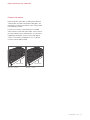
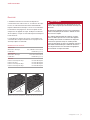
Product Information
Important product information, including the model and
serial number, are listed on the product rating plate. The
rating plate is located on the bottom of the cooktop. Refer
to the illustrations below.
If service is necessary, contact Wolf Factory Certied
Service with the model and serial number. For the name of
the nearest Wolf Factory Certied Service or for questions
regarding the installation, visit the contact and support
section of our website, wolfappliance.com, or call Wolf
Customer Care at 800-222-7820.
Induction cooktop
Electric cooktop
RATING PLATE RATING PLATE
INDUCTION/ELECTRIC COOKTOP

4
|
Wolf Customer Care 800.222.7820
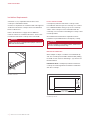
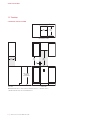
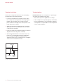
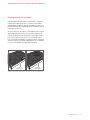
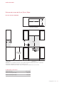
Installation Requirements
A minimum 2" (51) is required from the bottom of the
cooktop to combustible materials.
Clearance is required for the conduit located at the right rear
of induction and electric cooktops. Refer to the illustration
below for dimensions.
Refer to the illustrations on pages 6–8 for additional
minimum clearances. Installation dimensions are the same
for induction and electric cooktops of the same width.
WARNING
Failure to locate the cooktop without proper clearances
will result in a re hazard.
SPECIFICATIONS
1
1
/4" (32)
2"
(51)
2"
(51)
Conduit clearance
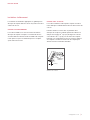
FLUSH INSTALLATION
Contemporary induction and electric cooktops can be
mounted ush with the top of the countertop or as a frame-
less standard installation sitting on top of the countertop
surface. If the cooktop is to be mounted ush with the
countertop, a recessed area surrounding the cooktop cutout
must be provided.
An installation kit and instructions required for a ush
installation are provided with the Contemporary cooktop.
CAUTION
A ush installation is intended for granite, solid surface,
or stone countertop surfaces only.
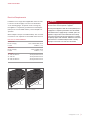
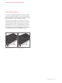
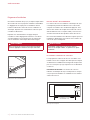
MULTIPLE COOKTOPS
When multiple cooktops or modules are installed side by
side, the countertop cutout width is determined by adding
the width of each unit, then subtracting 1"
(25). Refer to the
illustration below.
IMPORTANT NOTE: Contemporary induction and electric
cooktops are not designed to be installed in combination
with other cooktops.
CUTOUT WIDTH
(COMBINED WIDTH OF COOKTOPS MINUS
1")
19
1
/2"
(495)
CUTOUT
DEPTH
2
1
/2" (64)
2
1
/2" (64)
Countertop cutout

wolfappliance.com
|
5
Electrical Requirements
Installation must comply with all applicable electrical codes.
Locate the electrical supply as shown in the illustrations
on the following pages. A separate circuit servicing only
this appliance is required. A ground fault circuit interrupter
(GFCI) is not recommended and may cause interruption of
operation.
When multiple cooktops are installed side by side, each unit
must have its own separate recommended electrical circuit.
ELECTRICAL REQUIREMENTS
INDUCTION
Electrical Supply 3-wire, 240/208 VAC, 60 Hz
Conduit exible 4'
(1.2 m)
ELECTRIC
Electrical Supply 3-wire, 240 VAC, 60 Hz
Conduit exible 4'
(1.2 m)
SERVICE
15" Induction/Electric 20 amp dedicated circuit
24" Induction 30 amp dedicated circuit
30" Induction/Electric 40 amp dedicated circuit
36" Induction/Electric 50 amp dedicated circuit
WARNING
The complete appliance must be properly grounded at
all times when electrical power is applied.
Do not ground appliance with the neutral (white) house
supply wire. A separate ground wire must be utilized.
If aluminum house supply wiring is utilized, splice the
appliance copper wire to the aluminum house wiring
using special connectors design and agency certied
for joining copper and aluminum. Follow the connector
manufacturer's recommended procedure carefully.
Improper connection can result in a re hazard.
SPECIFICATIONS
Induction cooktop
Electric cooktop
RATING PLATE RATING PLATE

6
|
Wolf Customer Care 800.222.7820
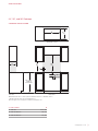
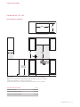
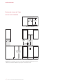
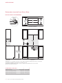
SPECIFICATIONS
15" Cooktop
STANDARD INSTALLATION
14"
(356)
19
1
/2"
(495)
2
1
/2" (64)
2
1
/2" (64)
FRONT VIEW
SIDE
VIEW
COUNTERTOP CUTOUT
NO
TE: Shaded area above countertop indicates minimum clearance to combustible surfaces,
combus
tible materials cannot be located within this area.
13"
(330)
18"
(457)
E
30"
(762)
2"
(51)
36" (914) min
FLOOR TO
COUNTERTOP

wolfappliance.com
|
7
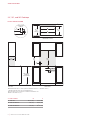
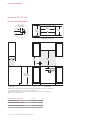
SPECIFICATIONS
E
COUNTERTOP CUTOUT
10" (254)
4
1
/2" (114)
3
1
/2" (89)
FRONT VIEW
SIDE
VIEW
NO
TE: Shaded area above countertop indicates minimum clearance to combustible surfaces,
combus
tible materials cannot be located within this area.
El
ectrical supply location only applies to installations with built-in oven.
30"
(762)
13"
(330)
18"
(457)
2"
(51)
W
WIDTH
19
1
/2"
(495)
2
1
/
2
"
(64)
2
1
/2" (64)
36" (914) min
FLOOR TO
COUNTERTOP
CUTOUT WIDTH
W
24" Induction 22
1
/8" (562)
30" Induction/Electric 29" (737)
36" Induction/Electric 35" (889)
24", 30", and 36" Cooktops
STANDARD INSTALLATION

8
|
Wolf Customer Care 800.222.7820
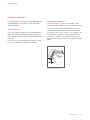
SPECIFICATIONS
24", 30", and 36" Cooktops
FLUSH INSTALLATION
E
A
RECESS
21
1
/8"
(537)
RECESS
1
9
/16" (40) min
W
CUTOUT WIDTH
COUNTERTOP CUTOUT
19
1
/2"
(495)
2
1
/2" (64)
2
1
/2" (64)
10" (254)
4
1
/2" (114)
3
1
/2" (89)
FRONT VIEW
SIDE
VIEW
NO
TE: Shaded area above countertop indicates minimum clearance to combustible surfaces,
combus
tible materials cannot be located within this area.
El
ectrical supply location only applies to installations with built-in oven.
Outsid
e corner radius
7
/16" (11).
30"
(762)
13"
(330)
18"
(457)
2"
(51)
5
/16"
(
8
)
7
/8"
(22) MAX
COUNTERTOP
PROFILE
36" (914) min
FLOOR TO
COUNTERTOP
CUTOUT WIDTH
W A
24" Induction 22
1
/8" (562) 23
3
/4" (603)
30" Induction/Electric 29" (737) 30
1
/8" (765)
36" Induction/Electric 35" (889) 36
1
/8" (918)

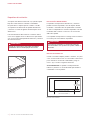
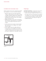
CLEAT OPTION
For this installation, the countertop cutout is the same size
as the outer edge of the cooktop glass.
Attach L-shaped cleats to the perimeter of the countertop
cutout. The top edge of the cleat cannot be wider than
7
/8" (22) and is attached
5
/16" (8) below the surface of the
countertop. Refer to the illustration below. Attach the cleats
to the countertop. Consult a countertop supplier for proper
methods of attachment.
INSTALLATION
Flush Installation
To ensure a proper installation, a template for the countertop
cutout should be created using the cooktop glass.
ROUTING OPTION
For this installation, a recessed area surrounding the coun-
tertop cutout is required. Fabrication of the recessed area
must take place before the countertop is installed.
This option is not recommended for countertops with a
molded backsplash.
7
/8" (22)
5
/16" (8)
L-SHAPED
CLEATS
Support cleats
wolfappliance.com
|
9

10
|
Wolf Customer Care 800.222.7820
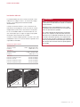
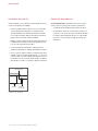
INSTALLATION
Cooktop Installation
Remove the cooktop and components from the shipping
package and recycle packing materials.
1 Lower the cooktop into the countertop cutout. Center
the cooktop in the opening with the front edge aligned
parallel to the front edge of the countertop. Using a
pencil, outline the rear edge of the cooktop on the coun-
tertop. Remove the cooktop.
2 Apply the foam strip to the perimeter of the countertop
opening. Refer to the illustration below. Do not seal the
cooktop to the countertop.
3 Insert the cooktop into the opening. Verify the cooktop is
aligned with the front edge of the countertop.
4 Attach the provided brackets to the bottom of the unit.
Insert the 3
1
/2" (89) clamping screws into the brackets.
Use a screwdriver to tighten the clamping screws
against the bottom of the countertop. Do not overtighten
screws. Refer to the illustration below.
Troubleshooting
IMPORTANT NOTE: If the cooktop does not operate prop-
erly, follow these troubleshooting steps:
• Verify electrical power is supplied to the cooktop.
• If the cooktop does not operate properly, contact Wolf
Factory Certied Service. Do not attempt to repair the
cooktop. Wolf is not responsible for service required to
correct a faulty installation.
FOAM STRIP
COUNTERTOP
BRACKET
CLAMPING
SCREW
Cooktop installation

Sub-Zero, Sub-Zero & Design, Sub-Zero & Snowake Design, Dual Refrigeration, The Living Kitchen, Great American Kitchens The Fine Art of Kitchen Design, Wolf, Wolf &
Design, Wolf Gourmet, W & Design, red colored knobs, Cove, and Cove & Design are registered trademarks and service marks of Sub-Zero Group, Inc. and its subsidiaries.
All other trademarks are property of their respective owners in the United States and other countries.

2
|
Atención al cliente de Wolf 800.222.7820
PARRILLA DE INDUCCIÓN/ELÉCTRICAS
Contenido
3 Parrilla de inducción/eléctricas
4 Especicaciones
9 Instalación
10 Resolución de problemas
Las características y especicaciones están sujetas a cam-
bios sin previo aviso. Visite wolfappliance.com/specs para
obtener la información más actualizada.
Aviso importante
Para garantizar que este producto se instale y opere de
la forma más segura y eciente posible, tome nota de los
siguientes tipos de información resaltada en esta guía:
AVISO IMPORTANTE señala la información que es especial-
mente importante.
PRECAUCIÓN indica una situación en la que se pueden
sufrir heridas leves o provocar daños al producto si no se
siguen las instrucciones.
ADVERTENCIA indica peligro de que se produzcan heridas
graves o incluso la muerte si no se siguen las precauciones.
AVISO IMPORTANTE: En toda esta guía, las dimensiones
entre paréntesis son milímetros, a menos que se especi-
que lo contrario.
AVISO IMPORTANTE: Guarde estas instrucciones para el
inspector eléctrico local.

wolfappliance.com
|
3
Información del producto
La información importante del producto, incluido el modelo
y número de serie de la unidad, se encuentra en la placa de
datos del producto. La placa de datos se localiza en la parte
baja de la parrilla. Consulte la siguiente ilustración.
Si necesita servicio, póngase en contacto con el servicio
autorizado de Wolf y tenga a mano el modelo y el número de
serie. Para obtener los datos del centro de servicio autori-
zado de Wolf más cercano o si tiene preguntas acerca de la
instalación, visite la sección de contacto y soporte técnico
en nuestra página de Internet wolfappliance.com o llame a la
línea de atención al cliente de Wolf al 800-222-7820.
Parrilla de inducción
Parrilla eléctrica
PLACA DE DATOS PLACA DE DATOS
PARRILLA DE INDUCCIÓN/ELÉCTRICAS

4
|
Atención al cliente de Wolf 800.222.7820
Requisitos de instalación
Se requiere una distancia mínima de 2" (51) desde la parte
baja de la estufa hasta los materiales combustibles.
El espacio libre se requiere para el conducto colocado
en la parte trasera derecha de las parrillas de inducción
y eléctricas. Consulte la siguiente ilustración para ver las
dimensiones.
Para otras distancias libres mínimas consulte las ilustra-
ciones en las páginas 6 a 8. Las dimensiones para instala-
ción son las mismas para parrillas de inducción y eléctricas
de la misma anchura.
ADVERTENCIA
La falta de espacios libres adecuados al instalar la
parrilla dará como resultado peligro de incendio.
ESPECIFICACIONES
1
1
/4" (32)
2"
(51)
2"
(51)
Dimensiones del conducto
INSTALACIÓN EMPOTRABLE
Las parrillas contemporáneas de inducción y eléctricas
pueden montarse empotradas, al ras de la parte alta del
mostrador, o asentadas sobre la supercie del mostrador,
sin marco. Si la parrilla va a montarse empotrada, al ras del
mostrador, debe contarse con un hueco en un área alre-
dedor de la parrilla.
Con la parrilla contemporánea se entrega un kit e instructivo
necesarios para una instalación empotrable.
PRECAUCIÓN
La instalación empotrable se recomienda solamente
para mostradores con supercies de granito, sólidas o
de piedra.
MULTIPLES PARRILLAS
Cuando se instalan múltiples parrillas o módulos, uno junto
a otro, la anchura del recorte en el mostrador se determina
por la suma de la
anchura de cada unidad, y luego se
resta 1"
(25). Consulte la siguiente ilustración.
AVISO IMPORTANTE: Las parrillas contemporáneas de
inducción y eléctricas no están diseñadas para instalarse
combinadas con otras parrillas.
ANCHURA DEL RECORTE
(ANCHURA COMBINADA DE
LAS PARRILLAS MENOS 1")
2
1
/2" (64)
2
1
/2" (64)
19
1
/2"
(495)
PROFUNDIDAD
DEL RECORTE
Recorte del mostrador

wolfappliance.com
|
5
ADVERTENCIA
Todo el electrodoméstico debe estar conectado a tierra
correctamente en todo momento cuando se suministre
energía eléctrica.
No ponga a tierra el electrodoméstico con el cable
neutro (blanco) de alimentación de la casa. Debe utili-
zarse un cable de tierra separado.
Si se utiliza cableado de aluminio para el suministro
de una casa, empalme el cable de cobre del electro-
doméstico con el cableado de aluminio de la casa con
conectores de diseño especial y con certicación de
la agencia para unir cobre y aluminio. Siga cuidadosa-
mente el procedimiento recomendado por el fabricante
del conector. Una conexión incorrecta puede producir
un incendio.
ESPECIFICACIONES
Instalación eléctrica
La instalación debe tener una conexión a tierra de confor-
midad con los códigos locales o, en ausencia de códigos
locales, con el Código Nacional de Electricidad,
ANSI/NFPA 70.
Coloque el suministro eléctrico como se muestra en las
ilustraciones de las páginas 6 a 8. Es necesario un circuito
independiente que dé servicio únicamente a este aparato.
No es recomendable utilizar un circuito de fallos de cone-
xión a tierra (GFCI, por sus siglas en inglés) ya que puede
interrumpir el funcionamiento de la unidad.
Cuando se instalan múltiples parrillas, una junto a otra, cada
unidad debe contar con su circuito eléctrico separado, de la
capacidad recomendada.
REQUISITOS ELÉCTRICOS
DE INDUCCIÓN
Suministro eléctrico 3 cables, 240/208 VCA, 60 Hz
Conducto exible de 4'
(1.2 m)
ELÉCTRICA
Suministro eléctrico 3 cables, 240 VCA, 60 Hz
Conducto exible de 4'
(1.2 m)
SERVICIO
De inducción / Eléctrica de 15" Circuito de 20 amps
De inducción de 24" Circuito de 30 amps
De inducción / Eléctrica de 30" Circuito de 40 amps
De inducción / Eléctrica de 36" Circuito de 50 amps
Parrilla de inducción
Parrilla eléctrica
PLACA DE DATOS PLACA DE DATOS

6
|
Atención al cliente de Wolf 800.222.7820
ESPECIFICACIONES
Parrilla de 15"
INSTALACIÓN ESTÁNDAR
14"
(356)
19
1
/2"
(495)
2
1
/2" (64)
2
1
/2" (64)
VISTA FRONTAL
VIST
A LATERAL
RECORTE DEL MOSTRADOR
NO
TA: La zona sombreada sobre el mostrador indica la distancia mínima a las superficies combustibles,
lo
s materiales combustibles no se pueden colocar en esta área.
13"
(330)
18"
(457)
E
30"
(762)
2"
(51)
36" (914) min
DE PISO A
MOSTRADOR

wolfappliance.com
|
7
ESPECIFICACIONES
E
RECORTE DEL MOSTRADOR
10" (254)
4
1
/2" (114)
3
1
/2" (89)
VISTA FRONTAL
VIST
A LATERAL
NO
TA: La zona sombreada sobre el mostrador indica la distancia mínima a las superficies combustibles,
lo
s materiales combustibles no se pueden colocar en esta área.
La
ubicación del suministro eléctrico solamente aplica para las instalaciones con horno empotrado.
30"
(762)
13"
(330)
18"
(457)
2"
(51)
Ancho
19
1
/2"
(495)
2
1
/
2
"
(64)
2
1
/2" (64)
36" (914) min
DE PISO A
MOSTRADOR
ANCHURA DEL RECORTE
Ancho
De inducción de 24" 22
1
/8" (562)
De inducción / Eléctrica de 30" 29" (737)
De inducción / Eléctrica de 36" 35" (889)
Parrillas de 24" | 30" | 36"
INSTALACIÓN ESTÁNDAR

8
|
Atención al cliente de Wolf 800.222.7820
ESPECIFICACIONES
Parrillas de 24" | 30" | 36"
INSTALACIÓN EMPOTRABLE
E
H
HUECO
21
1
/8"
(537)
HUECO
1
9
/16" (40) min
Ancho
RECORTE DEL MOSTRADOR
19
1
/2"
(495)
2
1
/2" (64)
2
1
/2" (64)
10" (254)
4
1
/2" (114)
3
1
/2" (89)
VISTA FRONTAL
VIST
A LATERAL
NO
TA: La zona sombreada sobre el mostrador indica la distancia mínima a las superficies combustibles,
lo
s materiales combustibles no se pueden colocar en esta área.
La
ubicación del suministro eléctrico solamente aplica para las instalaciones con horno empotrado.
Radi
o exterior de la esquina
7
/16" (11).
30"
(762)
13"
(330)
18"
(457)
2"
(51)
5
/16"
(
8
)
7
/8"
(22) MAX
PERFIL DEL
MOSTRADOR
36" (914) min
DE PISO A
MOSTRADOR
ANCHURA DEL RECORTE
Ancho H
De inducción de 24" 22
1
/8" (562) 23
3
/4" (603)
De inducción / Eléctrica de 30" 29" (737) 30
1
/8" (765)
De inducción / Eléctrica de 36" 35" (889) 36
1
/8" (918)

wolfappliance.com
|
9
OPCIÓN DE CORNAMUSA
Para esta instalación, el recorte del mostrador será del
mismo tamaño que el borde exterior del vidrio de la parrilla.
Fije cornamusas tipo "L" en el perímetro del recorte del
mostrador. El borde superior de la cornamusa no puede
ser más ancho de
7
/8" (22) y se jará
5
/16" (8) por debajo de
la supercie del mostrador. Consulte la siguiente ilustra-
ción. Fije las cornamusas al mostrador. Consulte con un
proveedor de mostradores cuál es el método adecuado de
jación.
INSTALACIÓN
Instalación empotrable
Para garantizar una instalación adecuada, debe elaborarse
una plantilla para el recorte del mostrador, utilizando el
vidrio de la parrilla.
OPCIÓN DE RUTA
Para esta instalación se requiere un área empotrada alre-
dedor del recorte del mostrador. La fabricación del área
empotrada debe llevarse a cabo antes de la instalación del
mostrador.
Esta opción no se recomienda para mostradores con pro-
tector contra salpicaduras integrado o moldeado.
7
/8" (22)
5
/16" (8)
CORNAMUSAS
EN "L"
Cornamusas de soporte

10
|
Atención al cliente de Wolf 800.222.7820
INSTALACIÓN
Instalación de la parrilla
Retire la parrilla y los componentes del empaque de envío y
recicle los materiales de embalaje.
1 Deslice la parrilla al interior del recorte en el mostrador.
Centre la parrilla en la abertura con el borde frontal
alineado paralelamente al borde frontal del mostrador.
Con ayuda de un lápiz, delinee el borde posterior de la
parrilla sobre el mostrador. Retire la parrilla.
2 Aplique la tira de espuma proporcionada al perímetro de
la abertura del mostrador. Consulte la siguiente ilustra-
ción. No selle la parrilla al mostrador.
3 Inserte la parrilla en la abertura. Compruebe que la
parrilla esté alineada con el borde frontal del mostrador.
4 Fije los soportes proporcionados a la parte inferior de la
unidad. Inserte los tornillos de jación de 3
1
/2" (89) en los
soportes. Utilice un destornillador para apretar los torni-
llos de jación contra el fondo del mostrador. No apriete
demasiado los tornillos. Consulte la siguiente ilustración.
Resolución de problemas
AVISO IMPORTANTE: Si la parrilla no funciona correcta-
mente, siga estos pasos para resolver los problemas:
• Compruebe que la parrilla tenga corriente eléctrica.
• Si la parrilla no funciona correctamente, póngase en
contacto con el centro de servicio autorizado de Wolf.
No intente reparar la parrilla. Wolf no es responsable
del servicio necesario para corregir una instalación
defectuosa.
TIRA DE ESPUMA
MOSTRADOR
SOPORTE
TORNILLO
DE FIJACIÓN
Instalación de la parrilla
A página está carregando ...
A página está carregando ...
A página está carregando ...
A página está carregando ...
A página está carregando ...
A página está carregando ...
A página está carregando ...
A página está carregando ...
A página está carregando ...
A página está carregando ...
A página está carregando ...
A página está carregando ...
-
 1
1
-
 2
2
-
 3
3
-
 4
4
-
 5
5
-
 6
6
-
 7
7
-
 8
8
-
 9
9
-
 10
10
-
 11
11
-
 12
12
-
 13
13
-
 14
14
-
 15
15
-
 16
16
-
 17
17
-
 18
18
-
 19
19
-
 20
20
-
 21
21
-
 22
22
-
 23
23
-
 24
24
-
 25
25
-
 26
26
-
 27
27
-
 28
28
-
 29
29
-
 30
30
-
 31
31
-
 32
32


em outros idiomas
- español: Wolf CI243TF/S Guía de instalación
- français: Wolf CI243TF/S Guide d'installation
- English: Wolf CI243TF/S Installation guide
