Hologic ATEC TriMark Biopsy Site Identification System Instruções de operação
- Tipo
- Instruções de operação

Instructions for Use
Gebruiksaanwijzing
Mode d’emploi
Bedienungsanleitung
Istruzioni per l’uso
Instruções de Utilização
Instrucciones de uso
Biopsy Site Identication System
Titanium Biopsy Site Marker


1English
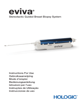
ATEC® TriMark®
Biopsy Site Marker System
Instructions for Use
Please read all information carefully. Failure to properly follow the instructions may lead to
unanticipated surgical consequences.
Important: This package insert is designed to provide Instructions for Use of the ATEC®
TriMark® biopsy site marker. It is not a reference to surgical techniques.
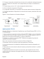
Upon completion of the ATEC breast biopsy procedure, the user will have the option of
using the ATEC TriMark biopsy site marker system by Hologic, Inc. Depending on the type
of application (imaging modality) used to guide the breast biopsy, the user will follow one
of the outlined processes for use of the ATEC TriMark biopsy site marker system. The
three imaging modalities used to guide deployment of the ATEC TriMark biopsy site marker
system include ultrasound (U/S), stereotactic x-ray (STX), and magnetic resonance imaging
(MRI). There are two deployment methods for the ATEC TriMark biopsy site marker system
associated with U/S and STX; both are described separately.
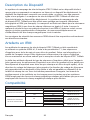
Indications
(Product codes TriMarkTD 13-12, TriMarkTD-2S-13-12, TriMarkTD 13-09,
TriMarkTD-2S-13-09, TriMarkTD 13-MR, TriMarkTD-2S-13-MR, TriMarkTD 36-
12, TriMarkTD-2S-36-12, TriMarkTD 36-09 and TriMarkTD-2S-36-09.)
The ATEC TriMark biopsy site marker system is indicated for use to mark an open or
percutaneous biopsy site to radiographically mark the location of the biopsy site.
Contraindications
None known.
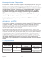
Device Description
The ATEC TriMark biopsy site marker system is a sterile, single use system comprised
of a titanium marker and a deployment device. The deployment device consists of a rigid
cannula, plunger, rigid push rod and handle. The ATEC TriMark biopsy site marker is
located at the distal end of the deployment device. The ATEC TriMark biopsy site marker
system may be used with imaging guidance (e.g., stereotactic x-ray, ultrasound and MRI).
The titanium marker is classied as magnetic resonance (MRI) conditional at 3.0 Tesla eld
strength or less. The marker, when present in a patient undergoing an MRI procedure at
3.0 Tesla or less, will not create an additional hazard or risk with respect to magnetic eld-
related interactions, movement/dislodgement, or heating.
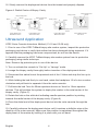
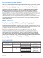
Safety information for MRI procedures should be performed according to the following
guidelines:

2English
MRI Artifacts
Artifacts for the ATEC TriMark biopsy site marker have been characterized using a 1.5
Tesla MRI system and T1-weighted, spin echo and gradient echo pulse sequences.
Based on this information, imaging quality may be slightly compromised if the area of
interest is in the exact same area as the ATEC TriMark biopsy site marker.
Artifact size is dependent on the type of pulse sequence used for imaging (larger for
gradient echo pulse sequences and smaller for spin echo and fast spin echo pulse
sequences), the direction of the frequency encoding direction (larger if the frequency
encoding direction is perpendicular to the device and smaller if it is parallel to the
device), and the size of the eld of view. Positional errors and artifacts on images will
be smaller for MRI systems with lower static magnetic eld strengths using the same
imaging parameters as those operating at higher static magnetic eld strengths.
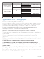
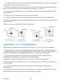
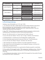
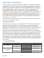
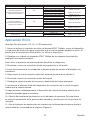
Compatibility
U/S
Approach Hand Piece Gauge Biopsy Site Access ATEC TriMark Device
Non Introducer Method
9G NA TriMark TD 13-09
TriMark TD-2S-13-09
NA
12G NA TriMark TD 13-12
TriMark TD-2S-13-12
NA
ATEC Outer Cannula
Introducer Method
9G
ATEC 0909-20 Outer Cannula
TriMark TD 13-09
TriMark TD-2S-13-09
ATEC 0909-12 Outer Cannula
ATEC 0912-20 Outer Cannula
ATEC 0912-12 Outer Cannula
12G ATEC 1209-20 Outer Cannula TriMark TD 13-12
TriMark TD-2S-13-12
ATEC 1212-20 Outer Cannula
STX
Approach Hand Piece Gauge Biopsy Site Access ATEC TriMark Device
ATEC Outer Cannula
Introducer Method
9G
ATEC 0909-20 Outer Cannula TriMark TD 13-09
TriMark TD-2S-13-09
ATEC 0909-12 Outer Cannula
ATEC 0912-20 Outer Cannula
ATEC 0912-12 Outer Cannula
12G ATEC 1209-20 Outer Cannula TriMark TD 13-12
TriMark TD-2S-13-12
ATEC 1212-20 Outer Cannula
ATEC Handpiece
Introducer Method
9G
ATEC 0909-20 Handpiece
TriMark TD 36-09
TriMark TD-2S-36-09
ATEC 0909-12 Handpiece
ATEC 0912-20 Handpiece
ATEC 0912-12 Handpiece
ATEC 0914-20 Handpiece
12G ATEC 1209-20 Handpiece TriMark TD 36-12
TriMark TS-2S-36-12
ATEC 1212-20 Handpiece
MRI
Approach Hand Piece Gauge Biopsy Site Access ATEC TriMark Device
ATEC Introducer
Sheath Method 9G ILS 0914-20 TriMark TD 13-MR
TriMark TD-2S-13-MR
ILS 0914-12

3English
Ultrasound Application
Non Introducer Method (13-12 and 13-09 only)
1. Prior to use of the ATEC TriMark biopsy site marker system, inspect the protective
packaging and device to verify that neither has been damaged during shipment. If it
appears that the packaging has been compromised, do not use the device.
2. Carefully remove the ATEC TriMark biopsy site marker system from its protective
packaging using sterile technique.
Note: Remove tip protector prior to use of the device.
3. Turn or activate the console to “Set Up” or “Lavage” mode.
4. Lavage the biopsy cavity thoroughly before insertion of the deployment device.
5. Disconnect the saline line at the proximal end of the Y-Valve.
6. Turn or activate the console to “Biopsy” mode.
7. Remove the handpiece from the breast and properly dispose.
8. Place the distal end of the deployment device into the needle tract that was created
by the outer cannula.
9. Carefully advance the deployment device to the desired marker deployment location.
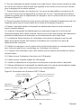
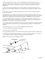
10. Locate the white directional arrow on the aperture indicator. This shows the
orientation of the marker aperture and the direction the marker will deploy.
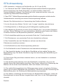
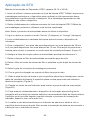
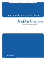
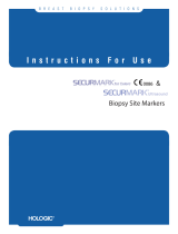
11. Rotate the aperture indicator so the white arrow is pointing towards the radial
center of the biopsy cavity. (Figure A)
12. Deploy the marker towards the center of the biopsy cavity by advancing the
deployment plunger with your thumb until it latches onto the aperture indicator.
13. After the audible and tactile click, release your thumb from the white plunger.
14. Rotate the aperture indicator 180 degrees.
15. Verify the deployment and proper position of the marker prior to removal of the
device.

4English
16. Slowly remove the deployment device from the breast and properly dispose.
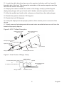
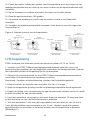
Figure A: Radial Center of Biopsy Cavity
Cores Taken From
Beside the Lesion
Cores Taken From
Above the Lesion
Cores Taken From
Below the Lesion
Cores Taken Around
the Clock
Marker
Marker Marker
Marker
Biopsy Cavity
Biopsy Cavity Biopsy Cavity
Biopsy Cavity
Biopsy Deployment
Device Biopsy Deployment
Device
Biopsy Deployment
Device
Biopsy Deployment
Device
12
12 12
12
6
6
6
6
99
333
3
9
9
Ultrasound Application
ATEC Outer Cannula Introducer Method (13-12 and 13-09 only)
1. Prior to use of the ATEC TriMark biopsy site marker system, inspect the protective
packaging and device to verify that neither has been damaged during shipment. If it
appears that the packaging has been compromised, do not use the device.
2. Carefully remove the ATEC TriMark biopsy site marker system from its protective
packaging using sterile technique.
Note: Remove tip protector prior to use of the device.
3. Turn or activate the console to “Set Up” or “Lavage” mode.
4. Lavage the biopsy cavity thoroughly before insertion of the deployment device.
5. Disconnect the saline line at the proximal end of the Y-Valve and strip the line up to
the hub.
6. While holding the hub rmly in one hand, rotate the handpiece 1/8 of a turn counter-
clockwise and pull-back to separate it from the outer cannula.
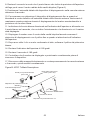
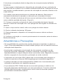
7. Pull back the hub 7mm for 20mm aperture devices or 3mm for 12mm aperture
devices. This will position the system to deploy the marker in the axial center of the
biopsy cavity. (Figure C)
8. Rotate the hub so the white dot indicating needle aperture position is pointing
towards the radial center of the biopsy cavity. (Figure A)
9. Place the distal end of the deployment device into the outer cannula through the
hub.
10. Carefully advance the deployment device until it reaches a denitive stop at the
distal tip of the outer cannula. Make sure this position is maintained throughout the
deployment of the marker by holding it in place with your o hand.

5 English
11. Locate the white directional arrow on the aperture indicator and line it up with
the white dot of the hub. This shows the orientation of the marker aperture and the
direction the marker will deploy.
12. Deploy the marker towards the center of the biopsy cavity by advancing the
deployment plunger with your thumb until it latches onto the aperture indicator.
13. After the audible and tactile click, release your thumb from the white plunger.
14. Rotate the aperture indicator 180 degrees.
15. Rotate the hub 180 degrees.
16. Verify the deployment and proper position of the marker prior to removal of the
device.
17. Slowly remove the deployment device and outer cannula/hub as one unit from the
breast and properly dispose.
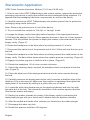
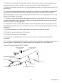
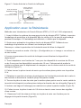
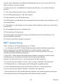
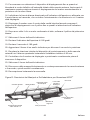
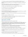
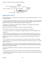
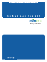
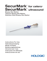
Figure B: ATEC TriMark Description
Filter Chamber Plug
(36 Only)
Deployment Guide
(36 Only)
36 Deployment Device
Aperture Indicator
Deployment Plunger 13 Deployment Device
Delivery Cannula
Tip Protector
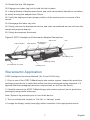
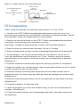
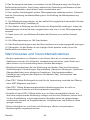
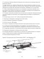
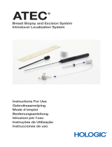
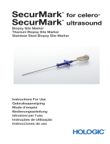
Figure C: Axial Center of Biopsy Cavity
For Standard (20mm) Aper-
tures =
or
For Petite (12mm) Apertures =
7mm
3mm
Axial Center of
Biopsy Cavity
Biopsy/Deployment
Device
Pull-Back PositionBiopsy Position
Marker

6English
Stereotactic Application
ATEC Outer Cannula Introducer Method (13-12 and 13-09 only)
1. Prior to use of the ATEC TriMark biopsy site marker system, inspect the protective
packaging and device to verify that neither has been damaged during shipment. If it
appears that the packaging has been compromised, do not use the device.
2. Carefully remove the ATEC TriMark biopsy site marker system from its protective
packaging using sterile technique.
Note: Remove tip protector prior to use of the device.
3. Turn or activate the console to “Set Up” or “Lavage” mode.
4. Lavage the biopsy cavity thoroughly before insertion of the deployment device.
5. Pull back the adapter 7mm for 20mm aperture devices or 3mm for 12mm aperture
devices. This will position the system to deploy the marker in the axial center of the
biopsy cavity. (Figure C)
6. Rotate the handpiece so the at surface is pointing towards 12 o’clock.
7. Disconnect the saline line at the proximal end of the Y-Valve and strip the line up to
the hub.
8. Rotate the handpiece so the at surface is pointing towards the radial center of the
biopsy cavity. The at surface shows where the needle aperture is pointing. (Figure A)
9. Engage one index ring lock to hold the hub in place. (Figure D)
10. Rotate the handpiece 1/8 of a turn counter-clockwise.
11. Unlock the retaining clamp, and pull the handpiece back to separate it from the
hub. (Figure D)
12. Place the distal end of the deployment device into the outer cannula through
the hub.
13. Carefully advance the deployment device until it reaches a denitive stop at the
distal tip of the outer cannula. Make sure this position is maintained throughout the
deployment of the marker by holding it in place with your o hand.
14. Locate the white directional arrow on the aperture indicator and line it up with
the white dot of the hub. This shows the orientation of the marker aperture and the
direction the marker will deploy.
15. Deploy the marker towards the center of the biopsy cavity by advancing the
deployment plunger with your thumb until it latches onto the aperture indicator.
16. After the audible and tactile click, release your thumb from the white plunger.
17. Disengage the index ring lock.
18. Rotate the aperture indicator 180 degrees.

7English
19. Rotate the hub 180 degrees.
20. Engage one index ring lock to hold the hub in place.
21. Initial pull-back of deployment device and outer cannula/hub should be controlled
by slowly moving the adapter back 20mm.
22. Verify the deployment and proper position of the marker prior to removal of the
device.
23. Disengage the index ring lock.
24. Slowly remove the deployment device and outer cannula/hub as one unit from the
breast and properly dispose.
25. Slowly decompress the breast.
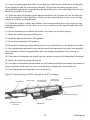
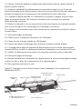
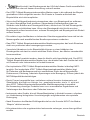
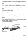
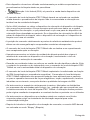
Figure D: ATEC Handpiece & Stereotactic Adapter Descriptions
Filter Chamber Filter Bracket Flat Surface of
Handpiece
Saline Line Hub
Index Ring Lock
Retaining Clamp
Cocking Lever
Proximal End of Y-Valve
Stereotactic Application
ATEC Handpiece Introducer Method (36-12 and 36-09 only)
1. Prior to use of the ATEC TriMark biopsy site marker system, inspect the protective
packaging and device to verify that neither has been damaged during shipment. If it
appears that the packaging has been compromised, do not use the device.
2. Carefully remove the ATEC TriMark biopsy site marker system from its protective
packaging using sterile technique.
Note: Remove tip protector prior to use of the device.
3. Turn or activate the console to “Set Up” or “Lavage” mode.
4. Lavage the biopsy cavity thoroughly before insertion of the deployment device.

8English
5. Pull back the adapter 7mm for 20mm aperture devices or 3mm for 12mm aperture
devices. This will position the system to deploy the marker in the axial center of the
biopsy cavity. (Figure C)
6. Disconnect the saline line at the proximal end of the Y-Valve.
7. Remove the lter chamber from the proximal end of the handpiece.
8. Remove the tissue lter from the lter chamber and replace it with the lter
chamber plug.
9. Remove deployment guide from the protective packaging.
10. Attach the deployment guide to the lter bracket of the handpiece.
11. Rotate the handpiece so the at surface is pointing towards the radial center of the
biopsy cavity. The at surface shows where the needle aperture is pointing. (Figure A)
12. Engage one index ring lock to hold the handpiece in place. (Figure D)
13. Carefully advance the deployment device through the deployment guide until
it reaches a denitive stop at the distal tip of the outer cannula. Make sure this
engagement is maintained throughout the deployment of the marker by holding it in
place with your o hand.
14. Locate the white directional arrow on the aperture indicator and line it up with the
at surface of the handpiece. This shows the orientation of the marker aperture and the
direction the marker will deploy.
15. Deploy the marker towards the center of the biopsy cavity by advancing the
deployment plunger with your thumb until it latches onto the aperture indicator.
Note: Following the insertion of the marker deployment device, the console should
NOT be put back into “biopsy” mode.
16. After the audible and tactile click, release your thumb from the white plunger.
17. Disengage the index ring lock. (Figure D)
18. Rotate the aperture indicator 180 degrees.
19. Rotate the handpiece 180 degrees.
20. Initial pull-back of deployment device and handpiece should be controlled by slowly
moving the adapter back 20mm.
21. Verify the deployment and proper position of the marker prior to removal of the
device.
22. Unlock the retaining clamp. (Figure D)

9English
23. Slowly remove the deployment device and handpiece as one unit from the breast
and properly dispose.
24. Slowly decompress the breast.
MRI Application
ATEC Introducer Sheath Method (13-MR only)
1. Prior to use of the ATEC TriMark biopsy site marker system, inspect the protective
packaging and device to verify that neither has been damaged during shipment. If it
appears that the packaging has been compromised, do not use the device.
2. Carefully remove the ATEC TriMark biopsy site marker system from its protective
packaging using sterile technique.
Note: Remove tip protector prior to use of the device.
3. Turn or activate the console to “Set Up” or “Lavage” mode.
4. Lavage the biopsy cavity thoroughly before insertion of the deployment device.
5. Disconnect the saline line at the proximal end of the Y-Valve.
6. Turn or activate the console to “Biopsy” mode.
7. Remove the handpiece from the Introducer Sheath and properly dispose.
8. Place the distal end of the deployment device through the Introducer Sheath.
9. Carefully advance the deployment device until the aperture indicator contacts
the Introducer Sheath hub. Make sure this position is maintained throughout the
deployment of the marker by holding it in place with your o hand.
10. Locate the white directional arrow on the aperture indicator. This shows the
orientation of the marker aperture and the direction the marker will deploy.
11. Rotate the aperture indicator so the white arrow is pointing towards the radial
center of the biopsy cavity. (Figure A)
12. Deploy the marker towards the center of the biopsy cavity by advancing the
deployment plunger with your thumb until it latches onto the aperture indicator.
13. After the audible and tactile click, release your thumb from the white plunger.
14. Rotate the aperture indicator 180 degrees.
15. Slowly remove the deployment device from the breast and properly dispose.
16. Verify the deployment and proper position of the marker prior to removal of the
Introducer Sheath.

10English
Warnings and Precautions
• There are possible adverse reactions when an object is implanted in the body. It is
the responsibility of the physician to evaluate any risk or benet prior to the use of this
device.
• Potential complications of marker clip placement consist of pain, seroma formation,
inammation, bruising, hematoma, hemorrhage, infections, hypersensitivity or allergic
reaction, soft tissue damage, misdiagnosis (due to marker clip migration), perforation
or scar tissue.
• The ATEC TriMark deployment device is not recommended for use within the bore of
an MRI magnet.
• The ATEC TriMark biopsy site marker system is not recommended for use in patients
with breast implants.
• The ATEC TriMark procedure should be performed only by physicians having
adequate training and familiarity with this procedure. Consult medical literature
relative to techniques, complications, and hazards prior to performance of any
minimally invasive procedure.
• This device should be used only by physicians trained in open or percutaneous
biopsy procedures.
• Caution: Federal (USA) law restricts this device to sale by or on the order
of a physician.
• The ATEC TriMark biopsy site marker should be deployed into the cavity created
during the biopsy procedure. Deployment into tissue outside of the biopsy cavity is
not recommended.
• If the deployment device is dicult to insert or remove from the biopsy device do
not apply excessive force. Excessive force may cause damage or breakage of the
deployment device which may result in a portion of the deployment device being left
behind in the patient. If the deployment device cannot be easily removed from the
biopsy device, remove the deployment device and the biopsy device as one unit.
• Marker position relative to established landmarks may change under mammography
upon subsequent breast compressions.
• The ATEC TriMark biopsy site marker is not intended to be repositioned or recaptured
after deployment.
• Excess hematoma within the biopsy cavity can lead to marker adhesion to the
deployment device, increasing the risk of marker drag out.

11 English
• Care should be taken to avoid damaging the cannula. Avoid operator or instrument
contact with the ATEC TriMark biopsy site marker or the distal end of the depployment
device.
• The implanted ATEC TriMark biopsy site marker is magnetic resonance imaging (MRI)
conditional. The implanted ATEC TriMark biopsy site marker presents no additional
risk to patient or operator from magnetic forces, torque, heating, induced voltages, or
movement, but it may aect MRI image quality.
• Minimally invasive instruments and accessories manufactured or distributed by
companies not authorized by Hologic, Inc., may not be compatible with the ATEC
TriMark biopsy site marker system. Use of such products may lead to unanticipated
results and possible injury to the user or patient.
• Instruments or devices which come into contact with bodily uids may require special
disposal handling to prevent biological contamination.
• Following the insertion of the marker deployment device, the console should NOT be
put into the “Biopsy” mode.
• Dispose of all opened instruments whether used or unused.
• Do not resterilize and/or reuse the ATEC TriMark biopsy site marker system.
Resterilization and/or reuse may compromise the integrity of the instrument. This may
lead to potential risks of failure of the device to perform as intended, and/or cross-
contamination associated with using inadequately cleaned and sterilized devices.
• If deployment guide is not used for 36-09 or 36-12 devices, damage may occur to the
deployment device, resulting in device malfunction.

12
English
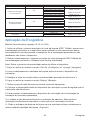
How Supplied
The ATEC TriMark biopsy site marker system is gamma sterilized and supplied
preloaded for single patient use. Discard into an appropriate container after use.
As Identied on Labels:
Number of Devices Enclosed.
YYYY-MM-DD Expiration date is represented by the following:
YYYY represents the year
MM represents the month
DD represents the day
For More Information
For technical support or reorder information in the United States, please contact:
Hologic, Inc.
250 Campus Drive
Marlborough, MA 01752 USA
Phone: 877-371-4372
International customers, contact your distributor or local Hologic Sales Representative:
Hologic BVBA
Da Vincilaan 5
1930 Zaventem
Belgium
Tel: +32 2 711 46 80

1313 Netherlands
Gebruiksaanwijzing
ATEC® TriMark®
biopsieplaatsmarkersysteem
Lees alle informatie zorgvuldig door. Het niet opvolgen van de instructies kan
onvoorziene chirurgische gevolgen hebben.
Belangrijk: Deze bijsluiter is bedoeld als gebruiksaanwijzing voor de ATEC® TriMark®
biopsieplaatsmarker. De bijsluiter is niet geschikt als referentiemateriaal voor
chirurgische technieken.
Nadat de ATEC borstbiopsie is uitgevoerd, kan de gebruiker gebruikmaken van het
ATEC TriMark biopsieplaatsmarkersysteem van Hologic, Inc. Afhankelijk van het
toepassingstype (beeldvormingsmodaliteit) dat wordt gebruikt om de borstbiopsie te
leiden, volgt de gebruiker een van de genoemde processen voor gebruik van het ATEC
TriMark biopsieplaatsmarkersysteem. De drie beeldvormingsmodaliteiten die worden
gebruikt om plaatsing van het ATEC TriMark biopsieplaatsmarkersysteem te leiden,
omvatten echograsche, stereotactische röntgen- en MRI-beeldvorming. Er zijn twee
plaatsingsmethoden mogelijk voor het ATEC TriMark biopsieplaatsmarkersysteem bij
gebruik van echograsche en stereotactische röntgenbeeldvorming; beide worden
afzonderlijk beschreven.
Indicaties
(Productcodes TriMarkTD 13-12, TriMarkTD-2S-13-12, TriMarkTD 13-09,
TriMarkTD-2S-13-09, TriMarkTD 13-MR, TriMarkTD-2S-13-MR, TriMarkTD
36-12, TriMarkTD-2S-36-12, TriMarkTD 36-09 en TriMarkTD-2S-36-09.)
Het ATEC TriMark biopsieplaatsmarkersysteem is geïndiceerd voor röntgenmarkering
van de plaats voor een open of percutane biopsie.
Contra-indicaties
Geen enkele contra-indicatie bekend.

14Nederlands
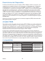
Beschrijving van het apparaat
Het ATEC TriMark biopsieplaatsmarkersysteem is een steriel systeem voor eenmalig
gebruik en bestaat uit een titanium marker en een plaatsingshulpmiddel. Het
plaatsingshulpmiddel bestaat uit een starre canule, een plunjer, een starre drukstang
en een handgreep. De ATEC TriMark biopsieplaatsmarker bevindt zich aan het distale
uiteinde van het plaatsingshulpmiddel. Het ATEC TriMark biopsieplaatsmarkersysteem
kan worden gebruikt onder geleiding van beeldvorming (zoals stereotactische
röntgen-, echograsche of MRI-beeldvorming). De titanium marker is geclassiceerd
als MRI-veilig onder bepaalde voorwaarden bij een veldsterkte van 3,0 Tesla of
minder. Wanneer de marker zich in een patiënt bevindt die een MRI-procedure bij 3,0
Tesla of minder ondergaat, vormt deze geen extra gevaar of risico met betrekking tot
interacties, beweging/losraken of opwarming gerelateerd aan magnetische velden.
De veiligheidsinformatie voor MRI-procedures moet worden nageleefd aan de hand
van de volgende richtlijnen:
MRI-artefacten
Er zijn artefacten voor de ATEC TriMark biopsieplaatsmarker gekenmerkt met behulp
van een MRI-systeem van 1,5 Tesla en T1-gewogen pulssequenties voor spin-echo
en gradiënt-echo. Op basis van deze informatie kan de kwaliteit van de beeldvorming
enigszins worden aangetast als het interessegebied zich in precies hetzelfde gebied
bevindt als de ATEC TriMark biopsieplaatsmarker.
De afmetingen van artefacten zijn afhankelijk van het type pulssequentie dat voor
de beeldvorming wordt gebruikt (groter voor pulssequenties voor gradiënt-echo en
kleiner voor pulssequenties voor spin-echo en snelle spin-echo), de richting van de
frequentiecodering (groter als de richting van de frequentiecodering loodrecht op het
hulpmiddel staat en kleiner als de richting van de frequentiecodering evenwijdig met
het hulpmiddel loopt) en de grootte van het gezichtsveld. Positiefouten en artefacten
op beelden zijn kleiner bij MRI-systemen met een lagere statische magnetische
veldsterkte bij gebruik van dezelfde beeldvormingsparameters als MRI-systemen met
een hogere statische magnetische veldsterkte.
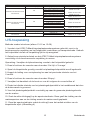
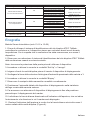
Compatibiliteit
U/S
Methode Handstuk gauge Toegang biopsieplaats ATEC Trimark™-apparaat
Methode zonder introducer
9G nvt TriMark TD 13-09
TriMark TD-2S-13-09
nvt
12G nvt TriMark TD 13-12
TriMark TD-2S-13-12
nvt
Methode met buitenste canule
als introducer
9G
ATEC 0909-20 Buitenste canule
TriMark TD 13-09
TriMark TD-2S-13-09
ATEC 0909-12 Buitenste canule
ATEC 0912-20 Buitenste canule
ATEC 0912-12 Buitenste canule
12G ATEC 1209-20 Buitenste canule TriMark TD 13-12
TriMark TD-2S-13-12
ATEC 1212-20 Buitenste canule

15 Nederlands
STX
Methode Handstuk gauge Toegang biopsieplaats ATEC Trimark™-apparaat
Methode met buitenste canule
als introducer
9G
ATEC 0909-20 Buitenste canule TriMark TD 13-09
TriMark TD-2S-13-09
ATEC 0909-12 Buitenste canule
ATEC 0912-20 Buitenste canule
ATEC 0912-12 Buitenste canule
12G ATEC 1209-20 Buitenste canule TriMark TD 13-12
TriMark TD-2S-13-12
ATEC 1212-20 Buitenste canule
Method met ATEC®-handstuk
als introducer
9G
ATEC 0909-20-handstuk
TriMark TD 36-09
TriMark TD-2S-36-09
ATEC 0909-12-handstuk
ATEC 0912-20-handstuk
ATEC 0912-12-handstuk
ATEC 0914-20-handstuk
12G ATEC 1209-20-handstuk TriMark TD 36-12
TriMark TS-2S-36-12
ATEC 1212-20-handstuk
MRI
Methode Handstuk gauge Toegang biopsieplaats ATEC Trimark™-apparaat
Methode met schede
als introducer 9G ILS 0914-20 TriMark TD 13-MR
TriMark TD-2S-13-MR
ILS 0914-12
U/S-toepassing
Methode zonder introducer (alleen 13-12 en 13-09)
1. Voordat u het ATEC TriMark biopsieplaatsmarkersysteem gebruikt, moet u de
beschermende verpakking en het hulpmiddel controleren op transportschade. Gebruik
het hulpmiddel niet als de verpakking lijkt te zijn aangetast.
2. Gebruik een steriele techniek om het ATEC TriMark biopsieplaatsmarkersysteem
voorzichtig uit de beschermende verpakking te nemen.
Opmerking: Verwijder de tipbescherming voordat u het hulpmiddel gebruikt.
3. Draai of activeer de console naar de modus ‘Set Up’ of ‘Lavage’.
4. Spoel de biopsieholte grondig voordat het plaatsingshulpmiddel wordt ingebracht.
5. Koppel de leiding voor zoutoplossing los aan het proximale uiteinde van het
Y-ventiel.
6. Draai of activeer de console naar de modus ‘Biopsy’.
7. Verwijder het handstuk uit de borst en voer dit volgens de voorschriften af.
8. Plaats het distale uiteinde van het plaatsingshulpmiddel in het naaldkanaal dat door
de buitencanule is gevormd.
9. Voer het plaatsingshulpmiddel voorzichtig op naar de gewenste plaatsingslocatie
van de marker.
10. Zoek de witte richtingspijl op de apertuurindicator. Deze geeft de richting van de
markerapertuur aan en de richting waarin de marker wordt geplaatst.
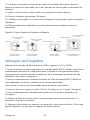
11. Draai de apertuurindicator zodat de witte pijl naar het radiale midden van de
biopsieholte wijst. (Afbeelding A)

16Nederlands
12. Plaats de marker richting het midden van de biopsieholte door de plunjer van het
plaatsingshulpmiddel met uw duim op te voeren tot deze op de apertuurindicator blijft
vastzitten.
13. Na de hoorbare en voelbare klik haalt u uw duim van de witte plunjer.
14. Draai de apertuurindicator 180 graden.
15. Controleer de plaatsing en positie van de marker voordat u het hulpmiddel
verwijdert.
16. Verwijder het plaatsingshulpmiddel langzaam uit de borst en voer dit volgens de
voorschriften af.
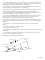
Figuur A: Radiaal centrum van de biopsieholte
Monsters genomen
naast de laesie
Monsters genomen
boven de laesie
Monsters genomen
onder de laesie
Monsters genomen
rondom rond
Markeerder
Mar-
keerder Markeerder
Markeerder
Biopsieholte
Biopsieholte Biopsieholte
Biopsieholte
Biopsie/
Plaatsingsinstrument Biopsie/
Plaatsingsinstrument
Biopsie/
Plaatsingsinstrument
Biopsie/
Plaatsingsinstrument
12
12 12
12
6
6
6
6
99
333
3
9
9
U/S-toepassing
ATEC®-methode met buitenste canule als introducer (alleen 12-13 en 13-09)
1. Voordat u het ATEC TriMark biopsieplaatsmarkersysteem gebruikt, moet u de
beschermende verpakking en het hulpmiddel controleren op transportschade. Gebruik
het hulpmiddel niet als de verpakking lijkt te zijn aangetast.
2. Gebruik een steriele techniek om het ATEC TriMark biopsieplaatsmarkersysteem
voorzichtig uit de beschermende verpakking te nemen.
Opmerking: Verwijder de tipbescherming voordat u het hulpmiddel gebruikt.
3. Draai of activeer de console naar de modus ‘Set Up’ of ‘Lavage’.
4. Spoel de biopsieholte grondig voordat het plaatsingshulpmiddel wordt ingebracht.
5. Koppel de leiding voor zoutoplossing los aan het proximale uiteinde van het Y-ventiel
en strip de leiding tot aan het aanzetstuk.
6. Houd het aanzetstuk stevig vast in één hand, draai het handstuk 1/8 slag naar links
en trek het terug om het van de buitencanule te scheiden.
7. Trek het aanzetstuk 7 mm terug bij hulpmiddelen met een apertuur van 20 mm of
3 mm bij hulpmiddelen met een apertuur van 12 mm. Hierdoor wordt het systeem
gepositioneerd om de marker in het axiale midden van de biopsieholte te plaatsen.
(Afbeelding C)

17 Nederlands
8. Draai het aanzetstuk zodanig dat de witte stip die de positie van de naaldapertuur
aangeeft naar het radiale midden van de biopsieholte wijst. (Afbeelding A)
9. Plaats het distale uiteinde van het plaatsingshulpmiddel in de buitencanule door het
aanzetstuk.
10. Voer het plaatsingshulpmiddel voorzichtig op totdat het een denitieve eindpositie
bij de distale tip van de buitencanule bereikt. Zorg ervoor dat deze positie wordt
gehandhaafd gedurende de plaatsing van de marker door het hulpmiddel met uw vrije
hand op zijn plaats te houden.
11. Zoek de witte richtingspijl op de apertuurindicator en lijn deze uit met de witte stip
van het aanzetstuk. Deze geeft de richting van de markerapertuur aan en de richting
waarin de marker wordt geplaatst.
12. Plaats de marker richting het midden van de biopsieholte door de plunjer van het
plaatsingshulpmiddel met uw duim op te voeren tot deze op de apertuurindicator blijft
vastzitten.
13. Na de hoorbare en voelbare klik haalt u uw duim van de witte plunjer.
14. Draai de apertuurindicator 180 graden.
15. Draai het aanzetstuk 180 graden.
16. Controleer de plaatsing en positie van de marker voordat u het hulpmiddel
verwijdert.
17. Verwijder het plaatsingshulpmiddel en de buitencanule/het aanzetstuk langzaam en
als één geheel uit de borst en voer de onderdelen volgens de voorschriften af.
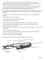
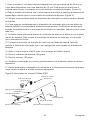
Figuur B: Beschrijvingen ATEC TriMark
Filterkamerplug
(alleen 36)
Plaatsingsgeleider
(alleen 36)
36 plaatsingsinstrument
Openingsindicator
Plaatsingsplunjer
Puntbeschermer
13 plaatsingsinstrument
Inbrengcanule

18Nederlands
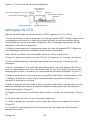
Figuur C: Axiaal centrum van de biopsieholte
Voor standard (20 mm)
openingen
of
Voor kleine (12 mm) openin-
gen
= 7mm
= 3mm
Axiaal centrum
van de
biopsieholte
Biopsie/
Plaatsingsinstrument
TerugtrekpositieBiopsieplaats
Markeerder
STX-toepassing
ATEC®-introducermethode met buitenste canule (alleen 13-12 en 13-09)
1. Voordat u het ATEC TriMark biopsieplaatsmarkersysteem gebruikt, moet u de
beschermende verpakking en het hulpmiddel controleren op transportschade. Gebruik
het hulpmiddel niet als de verpakking lijkt te zijn aangetast.
2. Gebruik een steriele techniek om het ATEC TriMark biopsieplaatsmarkersysteem
voorzichtig uit de beschermende verpakking te nemen.
Opmerking: Verwijder de tipbescherming voordat u het hulpmiddel gebruikt.
3. Draai of activeer de console naar de modus ‘Set Up’ of ‘Lavage’.
4. Spoel de biopsieholte grondig voordat het plaatsingshulpmiddel wordt ingebracht.
5. Trek de adapter 7 mm terug bij hulpmiddelen met een apertuur van 20 mm of
3 mm bij hulpmiddelen met een apertuur van 12 mm. Hierdoor wordt het systeem
gepositioneerd om de marker in het axiale midden van de biopsieholte te plaatsen.
(Afbeelding C)
6. Draai het handstuk zodat het platte oppervlak omhoog is gericht (12 uurspositie).
7. Koppel de leiding voor zoutoplossing los aan het proximale uiteinde van het Y-ventiel
en strip de leiding tot aan het aanzetstuk.
8. Draai het handstuk zodat het platte oppervlak naar het radiale midden van de
biopsieholte wijst. Het platte oppervlak geeft aan waar de naaldapertuur naartoe wijst.
(Afbeelding A)
9. Maak één indexringvergrendeling vast om het aanzetstuk op zijn plaats te houden.
(Afbeelding D)
10. Draai het handstuk 1/8 slag naar links.
11. Maak de borgklem los en trek het handstuk terug om het van het aanzetstuk te
scheiden. (Afbeelding D)
12. Plaats het distale uiteinde van het plaatsingshulpmiddel in de buitencanule door
het aanzetstuk.
A página está carregando...
A página está carregando...
A página está carregando...
A página está carregando...
A página está carregando...
A página está carregando...
A página está carregando...
A página está carregando...
A página está carregando...
A página está carregando...
A página está carregando...
A página está carregando...
A página está carregando...
A página está carregando...
A página está carregando...
A página está carregando...
A página está carregando...
A página está carregando...
A página está carregando...
A página está carregando...
A página está carregando...
A página está carregando...
A página está carregando...
A página está carregando...
A página está carregando...
A página está carregando...
A página está carregando...
A página está carregando...
A página está carregando...
A página está carregando...
A página está carregando...
A página está carregando...
A página está carregando...
A página está carregando...
A página está carregando...
A página está carregando...
A página está carregando...
A página está carregando...
A página está carregando...
A página está carregando...
A página está carregando...
A página está carregando...
A página está carregando...
A página está carregando...
A página está carregando...
A página está carregando...
A página está carregando...
A página está carregando...
A página está carregando...
A página está carregando...
A página está carregando...
A página está carregando...
A página está carregando...
A página está carregando...
A página está carregando...
A página está carregando...
A página está carregando...
A página está carregando...
A página está carregando...
A página está carregando...
A página está carregando...
A página está carregando...
A página está carregando...
A página está carregando...
A página está carregando...
A página está carregando...
A página está carregando...
A página está carregando...
A página está carregando...
A página está carregando...
A página está carregando...
A página está carregando...
-
 1
1
-
 2
2
-
 3
3
-
 4
4
-
 5
5
-
 6
6
-
 7
7
-
 8
8
-
 9
9
-
 10
10
-
 11
11
-
 12
12
-
 13
13
-
 14
14
-
 15
15
-
 16
16
-
 17
17
-
 18
18
-
 19
19
-
 20
20
-
 21
21
-
 22
22
-
 23
23
-
 24
24
-
 25
25
-
 26
26
-
 27
27
-
 28
28
-
 29
29
-
 30
30
-
 31
31
-
 32
32
-
 33
33
-
 34
34
-
 35
35
-
 36
36
-
 37
37
-
 38
38
-
 39
39
-
 40
40
-
 41
41
-
 42
42
-
 43
43
-
 44
44
-
 45
45
-
 46
46
-
 47
47
-
 48
48
-
 49
49
-
 50
50
-
 51
51
-
 52
52
-
 53
53
-
 54
54
-
 55
55
-
 56
56
-
 57
57
-
 58
58
-
 59
59
-
 60
60
-
 61
61
-
 62
62
-
 63
63
-
 64
64
-
 65
65
-
 66
66
-
 67
67
-
 68
68
-
 69
69
-
 70
70
-
 71
71
-
 72
72
-
 73
73
-
 74
74
-
 75
75
-
 76
76
-
 77
77
-
 78
78
-
 79
79
-
 80
80
-
 81
81
-
 82
82
-
 83
83
-
 84
84
-
 85
85
-
 86
86
-
 87
87
-
 88
88
-
 89
89
-
 90
90
-
 91
91
-
 92
92


Hologic ATEC TriMark Biopsy Site Identification System Instruções de operação
- Tipo
- Instruções de operação
em outras línguas
- español: Hologic ATEC TriMark Biopsy Site Identification System Instrucciones de operación
- français: Hologic ATEC TriMark Biopsy Site Identification System Mode d'emploi
- italiano: Hologic ATEC TriMark Biopsy Site Identification System Istruzioni per l'uso
- Nederlands: Hologic ATEC TriMark Biopsy Site Identification System Handleiding
- Deutsch: Hologic ATEC TriMark Biopsy Site Identification System Bedienungsanleitung
Artigos relacionados
-
 Hologic TriMark Instruções de operação
-
 Hologic Eviva Stereotactic Guided Breast Biopsy System Instruções de operação
-
 Hologic ATEC Breast Biopsy and Excision System Ultrasound Introducer Instruções de operação
-
 Hologic TriMark Instruções de operação
-
 Hologic CeleroMark Instruções de operação
-
 Hologic ATEC Breast Biopsy and Excision System Introducer Localization System Instruções de operação
-
 Hologic ATEC Handpiece Instruções de operação
-
 Hologic SecurMark Instruções de operação
-
 Hologic SecurMark Instruções de operação
-
 Hologic SecurMark Instruções de operação


