
SPI-20, SP1-25 & SPI-RF
Installation Manual
Eective: February 2021
ALT.
ON
ALT.
ON
SPI-RF
AUX
MAIN
AC OUPUT
TEST POINT
RF
IN/
OUT
BLACK
MAIN
WHITE
GND
GRND
AUX
AUX MAIN
SURGE PROTECTOR
EQUIPPED
LEVEL
PAD
SCREW
ACCESS

SPI-20, SPI-25 & SPI-RF
Installation Manual
745-997-C0-001, Rev. B
Eective Date: February 2021
©
2021 by Alpha Technologies Services, Inc.
Disclaimer
Images contained in this manual are for illustrative purposes only. These images may not match your installation.
Operator is cautioned to review the drawings and illustrations contained in this manual before proceeding. If there are
questions regarding the safe operation of this powering system, please contact Alpha Technologies Services, Inc. or your
nearest Alpha
®
representative.
Alpha Technologies Services, Inc. shall not be held liable for any damage or injury involving its enclosures, power
supplies, generators, batteries or other hardware if used or operated in any manner or subject to any condition not
consistent with its intended purpose or is installed or operated in an unapproved manner or improperly maintained.
Notice of FCC Compliance
Per FCC 47 CFR 15.21:
Changes or modications not expressly approved by the party responsible for compliance could void the user’s authority to
operate the equipment.
Per FCC 47 CFR 15.105:
This equipment has been tested and found to comply with the limits for a Class A digital device, pursuant to part 15 of the
FCC Rules. These limits are designed to provide reasonable protection against harmful interference when the equipment
is operated in a commercial environment. This equipment generates, uses and can radiate radio frequency energy and, if
not installed and used in accordance with the instruction manual, may cause harmful interference to radio communications.
Operation of this equipment in a residential area is likely to cause harmful interference in which case the user will be required
to correct the interference at their own expense.
Contact Information
Sales information and customer service in USA
(7AM to 5PM, Pacic Time):
Complete technical support in USA
(7AM to 5PM, Pacic Time or 24/7 emergency support):
Sales information and technical support in Canada:
Website:
+1 800 863 3364
+1 888 462 7487
www.alpha.com
+1 800 322 5742

3745-997-C0-001 Rev. B (02/2021)
Table of Contents
SPI-20, 25 & RF Safety & Compliance Notes ...................................................................................................... 4
1.0 Introduction ................................................................................................................................................. 6
2.0 Installation ................................................................................................................................................... 7
2.1 SPI-20 and SPI-25 Installation ............................................................................................................... 7
2.2 SPI-RF Installation ................................................................................................................................. 9
3.0 Specications ............................................................................................................................................ 10
Figures
Fig. 1-1, SPI-20 ......................................................................................................................................................................6
Fig. 1-4, SPI-RF......................................................................................................................................................................6
Fig. 1-2, SPI-20 and SPI-25 Rear...........................................................................................................................................6
Fig. 1-3, SPI-25 ......................................................................................................................................................................6
Fig. 2-2, Channel Lock Plier Locations ...................................................................................................................................7
Fig. 2-1, SPI Mounting Locations ...........................................................................................................................................7
Fig. 2-3, SPI Hardware Stack Up ...........................................................................................................................................7
Fig. 2-5, Pole and Ground Mount Enclosure Installation (SPI-20 & SPI-25) ..........................................................................8
Fig. 2-4, SPI Installation .........................................................................................................................................................8
Fig. 2-6, SPI-RF Hardware Stack Up .....................................................................................................................................9
Fig. 2-7, Pole and Ground Mount Enclosure Installation (SPI-RF) .........................................................................................9
Tables
Table 3-1, Specications.......................................................................................................................................................10

4 745-997-C0-001 Rev. B (02/2021)
SPI-20, 25 & RF Safety & Compliance Notes
Review the drawings and illustrations contained in this document before proceeding. If there are any questions regarding the safe installation or
operation of the system, contact Alpha Technologies Services, Inc. or the nearest Alpha
®
representative. Save this document for future reference.
To reduce the risk of injury or death and to ensure the continued safe operation of this product, the following symbols have been placed throughout this
manual. Where these symbols appear, use extra care and attention.
NOTICE provides additional information to help complete a specic task or procedure.
NOTICE:
SPI-20, 25 und RF – Sicherheits- und Konformitätshinweise
Überprüfen Sie die in diesem Dokument enthaltenen Zeichnungen und Abbildungen,
bevor Sie fortfahren. Wenn Sie Fragen zur sicheren Installation oder zum sicheren Betrieb
des Systems haben, wenden Sie sich an Alpha Technologies Services, Inc. oder an die
nächstgelegene Vertretung von Alpha
®
. Behalten Sie dieses Dokument zur späteren
Verwendung.
Um die Verletzungs- oder Todesgefahr zu verringern und den sicheren Betrieb dieses
Produkts zu gewährleisten, wurden die folgenden Symbole in diesem Handbuch
durchgehend angebracht. Wo diese Symbole erscheinen, ist besondere Vorsicht und
Aufmerksamkeit geboten.
HINWEIS bietet zusätzliche Informationen, die bei
der Erledigung einer bestimmten Aufgabe oder eines
bestimmten Verfahrens helfen.
HINWEIS:
• This equipment has been investigated by regulatory authorities for use in various Alpha enclosures. If a non-Alpha enclosure is being used, it is the
operator or installer's responsibility to ensure the combination conforms to your local regulatory requirements.
• This equipment is intended for installation in a restricted access area (MDU) or in another enclosure in the nal application.
• This equipment shall be installed and congured by qualied service personnel only, according to the installation instructions provided.
• All models have a Hazardous Voltage Secondary input and output (CATV).
• This product is intended for and tested with the manufacturers CATV power supplies and enclosures which are powered from mains and provided
with 20 A branch circuit protection.
• Evaluated for use at 60ºC/-40 ºC (internal) ambient temperature, Pollution Degree 3 environment.
• The above models are not suitable for direct outdoor installation without a suitable enclosure.
• This equipment is intended for use in a national two wire CATV system. Line-Neutral/Ground is functional and relies upon multipoint grounding
of the end-use enclosure for safety. Acceptability of this equipment in the end-use CATV system is to be determined by the authority having
jurisdiction (AHJ) or NCB.
• The equipment contains VDRs and gas tubes bridging insulation. Acceptability shall be determined by the accepting (AHJ) or NCB.
• Intended to be connected to a CABLE DISTRIBUTION SYSTEM with a maximum external transient overvoltage rating of 4000Vpk and a CATV
supply with OVCII hazardous secondary output.
• Dieses Gerät wurde von den Aufsichtsbehörden für den Einsatz in verschiedenen
Alpha-Gehäusen untersucht. Wenn ein Gehäuse eines anderen Herstellers als
Alpha verwendet wird, ist der Betreiber oder Installateurs dafür verantwortlich,
die Konformität der Kombination mit den Vorgaben der lokalen Behörden zu
gewährleisten.
• Dieses Gerät ist für die Installation in einem geschützten Bereich (MDU) oder in
einem weiteren Gehäuse für die endgültige Anwendung vorgesehen.
• Dieses Gerät darf nur von qualizierten Fachkräften gemäß der beiliegenden
Installationsanleitung installiert oder konguriert werden.
• Alle Modelle sind mit einem sekundären Ein- und Ausgang (CATV) für gefährliche
Spannungen versehen.
• Dieses Produkt ist auf die Verwendung von CATV-Netzteilen und Gehäuse des
Herstellers ausgelegt und getestet, die über das Stromnetz gespeist werden und
über einen auf 20 A abegsicherten Nebenstromkreisschutz verfügen.
• Bemessen für Umgebungen mit einer Temperatur von -40 bis +60 ºC (intern) und
Verschmutzungsgrad 3.
• Die obigen Modelle sind nicht für eine direkte Installation im Freien ohne ein
entsprechendes Gehäuse geeignet.
• Dieses Gerät ist für den Einsatz in einem nationalen zweiadrigen Fernsehkabelnetz
(CATV) vorgesehen. Die Konguration Leiter-Neutral/Erde ist sicherheitstechnisch
funktionell und abhängig von einer Mehrpunkt-Erdung am Gehäuse des
Endverbrauchers. Die Abnahme dieses Geräts im CATV-System des
Endverbrauchers muss den Vorgaben der zuständigen Behörde (AHJ) oder NCB
entsprechen.
• Dieses Gerät enthält VDRs und eine Isolierung gegen Wärmeüberbrückung für
Gasrohrleitungen. Die Abnahme muss den
• Vorgaben der zuständigen Behörde (AHJ) oder NCB entsprechen.
• Vorgesehen für den Anschluss an ein KABELVERTEILERSYSTEM mit einer
maximalen externen transienten Überspannung von 4000 Vpk und einer CATV-
Versorgung mit Sekundärausgang für gefährliche Spannungen (OVCII).
SPI-20, 25 et RF Remarques sur la sécurité et la conformité
Passez en revue les dessins et les illustrations contenus dans le présent document avant de procéder.
Pour toute question concernant l’installation ou le fonctionnement sécuritaire du système, veuillez
communiquer avec Alpha Technologies Services, Inc., ou le représentant Alpha
MC
le plus près. Veuillez
conserver le présent document pour le consulter ultérieurement.
An de réduire le risque de blessure ou de mort, et pour assurer le fonctionnement continu et sécuritaire de
ce produit, les symboles suivants ont été répartis dans l’ensemble du manuel. Lorsque ces symboles sont
présents, veuillez faire preuve de plus de prudence et d’attention.
« AVIS » fournit des renseignements supplémentaires pour aider à
terminer une tâche ou une procédure
particulière.
AVIS :
• Cet équipement a fait l’objet d’une enquête par les autorités réglementaires pour une utilisation
dans diverses armoires Alpha. Si une armoire autre qu’une armoire Alpha est utilisée, l’opérateur
ou l’installateur a la responsabilité de s’assurer que la combinaison se conforme aux exigences
réglementaires locales.
• Cet équipement est conçu pour une installation dans une zone à accès restreint (multilogements à
l’intérieur) ou dans une autre armoire dans l’application nale.
• Cet équipement doit être installé ou conguré par le personnel d’entretien qualié seulement,
conformément aux directives d’installation fournies avec chaque appareil.
• Tous les modèles sont équipés d’une entrée et d’une sortie auxiliaire pour tension dangereuse
(CATV).
• Ce produit est conçu et testé pour une utilisation avec les blocs d’alimentations CATV et les
armoires du fabricant qui sont alimentées par les lignes principales et fournies avec circuit de
dérivation de protection de 20 A.
• Évalué pour une utilisation à température ambiante entre 60 ºC et -40 ºC (intérieur) et un
environnement de pollution de type 3.
• Les modèles ci-dessus ne conviennent pas à une installation directe à l’extérieur sans armoire
adéquate.
• Cet équipement est conçu pour une utilisation dans un système CATV national à deux câbles. La
ligne électrique, le neutre et la mise à la terre sont fonctionnels et reposent sur la mise à la terre
multipoint de l’armoire d’utilisation nale pour la sécurité. L’acceptabilité de cet équipement dans
le système CATV d’utilisation nale doit être déterminée par l’autorité compétente ou NCB.
• Cet équipement contient un pont thermique avec résistances VDR et des tubes à gaz faisant le
pont avec l’isolation. L’acceptabilité sera déterminée par l’autorité compétente ou NCB.
• Conçu pour une connexion à un SYSTÈME DE CÂBLODISTRIBUTION avec une valeur de
surtension externe maximum de 4 000 Vpk et un bloc d’alimentation CATV avec sortie auxiliaire
de tension dangereuse de classe OVCII.

5745-997-C0-001 Rev. B (02/2021)
Notas de seguridad y cumplimiento de SPI-20, 25 & RF
Revise los dibujos e ilustraciones que guran en este documento antes de continuar. Si tiene
alguna pregunta sobre la instalación o el funcionamiento seguro del sistema, póngase en contacto
con Alpha Technologies Services, Inc. o con el representante más cercano de Alpha
®
. Guarde
este documento para futuras referencias.
Para reducir el riesgo de lesiones o muerte y para garantizar el funcionamiento seguro y continuo
de este producto, se han colocado los siguientes símbolos en este manual. Cuando aparezcan
estos símbolos, tenga mucho cuidado y atención.
• Esta equipo ha sido investigada por las autoridades reguladoras para su uso en diversos
gabinetes Alpha. De utilizarse un gabinete que no sea Alpha, es responsabilidad del
operador o instalador garantizar que la combinación cumpla con sus requerimientos
regulatorios locales.
• El equipo está diseñado para su instalación en un área de acceso restringido (MDU) o en
otro gabinete en la aplicación nal.
• El equipo deberá ser instalado y congurado únicamente por personal de servicio
calicado, de acuerdo con las instrucciones de instalación suministradas.
• Todos los modelos tienen una entrada y salida (CATV) secundaria de voltaje peligroso.
• Este producto está diseñado y probado con las fuentes de alimentación CATV y los
gabinetes del fabricante que son alimentados de la red eléctrica y tienen una protección de
circuito derivado de 20 A.
• Evaluado para ser usado a temperatura ambiente de 60º C/-40º C (interna), entornos
grado 3 de contaminación.
• Los modelos anteriores no son adecuados para instalación exterior directa sin un gabinete
adecuado.
• Este equipo está diseñado para ser utilizado en un sistema nacional CATV de dos cables.
Línea a neutro / a tierra es funcional y se basa en conexión a tierra de varios puntos del
gabinete de uso nal por razones de seguridad. La admisibilidad de este equipo en el
sistema CATV de uso nal será determinada por la autoridad que tenga jurisdicción (AHJ)
o NCB.
• El equipo contiene aislamiento con puente VDR y tubos de gas. La admisibilidad será
determinada por la jurisdicción (AHJ) o NCB que lo acepte.
• Diseñado para ser conectado a un SISTEMA DE DISTRIBUCIÓN DE CABLE con un rango
de sobrevoltaje transitorio externo máximo de 4000 Vpk y un suministro CATV con salida
secundaria OVCII peligrosa.
AVISO proporciona información adicional para ayudar a
completar una tarea o procedimiento especíco.
AVISO:
Notas de seguridad y cumplimiento de SPI-20, 25 & RF
Revise los dibujos e ilustraciones que guran en este documento antes de continuar. Si tiene
alguna pregunta sobre la instalación o el funcionamiento seguro del sistema, póngase en contacto
con Alpha Technologies Services, Inc. o con el representante más cercano de Alpha
®
. Guarde
este documento para futuras referencias.
Para reducir el riesgo de lesiones o muerte y para garantizar el funcionamiento seguro y continuo
de este producto, se han colocado los siguientes símbolos en este manual. Cuando aparezcan
estos símbolos, tenga mucho cuidado y atención.
• Esta equipo ha sido investigada por las autoridades reguladoras para su uso en diversos
gabinetes Alpha. De utilizarse un gabinete que no sea Alpha, es responsabilidad del
operador o instalador garantizar que la combinación cumpla con sus requerimientos
regulatorios locales.
• El equipo está diseñado para su instalación en un área de acceso restringido (MDU) o en
otro gabinete en la aplicación nal.
• El equipo deberá ser instalado y congurado únicamente por personal de servicio
cualicado, de acuerdo con las instrucciones de instalación provistas.
• Todos los modelos tienen una entrada y salida (CATV) secundaria de voltaje peligroso.
• Este producto está diseñado y probado con las fuentes de alimentación CATV y los
gabinetes del fabricante que son alimentados de la red eléctrica y tienen una protección de
circuito derivado de 20 A.
• Evaluado para ser usado a temperatura ambiente de 60º C/-40º C (interna), entornos
grado 3 de contaminación.
• Los modelos anteriores no son adecuados para instalación exterior directa sin un gabinete
adecuado.
• Este equipo está diseñado para ser utilizado en un sistema nacional CATV de dos cables.
Línea a neutro / a tierra es funcional y se basa en conexión a tierra de varios puntos del
gabinete de uso nal por razones de seguridad. La admisibilidad de este equipo en el
sistema CATV de uso nal será determinada por la autoridad que tenga jurisdicción (AHJ)
o NCB.
• El equipo contiene aislamiento con puente VDR y tubos de gas. La admisibilidad será
determinada por la jurisdicción (AHJ) o NCB que lo acepte.
• Diseñado para ser conectado a un SISTEMA DE DISTRIBUCIÓN DE CABLE con un rango
de sobrevoltaje transitorio externo máximo de 4000 Vpk y un suministro CATV con salida
secundaria OVCII peligrosa.
AVISO proporciona información adicional para ayudar a
completar una tarea o procedimiento especíco.
AVISO:
Notas de Conformidade e Segurança SPI-20, 25 e RF
Veja os desenhos e ilustrações contidos neste documento antes de continuar. Se surgir qualquer
dúvida sobre como instalar ou operar com segurança o sistema, contate a Alpha Technologies
Services, Inc. ou o representante mais próximo da Alpha
®
. Guarde este documento para futuras
consultas.
Para reduzir o risco de lesões ou morte e assegurar a operação segura continuada deste produto,
os seguintes símbolos acompanham as instruções deste manual. Ao encontrar estes símbolos,
recomenda-se maior precaução e atenção.
• O uso desta equipamento foi analisado em diversos invólucros Alpha por autoridades
regulatórias. Se for usado um gabinete de outra marca que não a Alpha, será
responsabilidade do operador ou instalador assegurar a conformidade da combinação com
seus requisitos regulatórios locais.
• Este equipamento deve ser instalado em uma área de acesso restrito (quadro de
distribuição) ou em outro gabinete na aplicação nal.
• Este equipamento deve ser instalado ou congurado apenas por pessoas qualicadas, de
acordo com as instruções de instalação fornecidas.
• Todos os modelos têm uma entrada e saída secundária de tensão perigosa (CATV).
• Este produto foi projetado e testado pelos fabricantes de fontes de alimentação de CATV
e gabinetes alimentados por rede elétrica e fornecidos com proteção de circuito de
ramicação de 20 A.
• Ele foi avaliado para uso em temperatura ambiente de 60°C / -40°C (interna) e ambiente
com Grau de Poluição 3.
• Os modelos acima não são adequados para instalação externa direta sem um gabinete
adequado.
• Este equipamento deve ser usado em um sistema nacional de CATV de dois os. As
linhas Fase-Neutro/Terra são funcionais e dependem do aterramento multiponto do
gabinete de uso nal para segurança. A aceitabilidade deste equipamento no sistema
CATV de uso nal deve ser determinada pelas autoridades responsáveis ou por entidades
nacionais certicadoras.
• O equipamento contém VDRs e tubos de gás que fazem a ponte de isolamento. Sua
aceitabilidade deve ser determinada pelas autoridades responsáveis ou por entidades
nacionais certicadoras.
• Seu uso se destina a ser conectado a um SISTEMA DE DISTRIBUIÇÃO DE CABOS com
uma classicação de sobretensão transiente externa máxima de 4000 Vpk e uma fonte de
CATV com saída secundária perigosa OVCII.
AVISO fornece informações adicionais para ajudar a realizar um
procedimento ou tarefa especíca.
AVISO:
Recomendações de Segurança e Conformidade SPI-20, 25 e RF
Veja os desenhos e ilustrações contidos neste documento antes de continuar. Se surgir qualquer
dúvida sobre como instalar ou operar com segurança o sistema, contate a Alpha Technologies
Services, Inc. ou o representante mais próximo da Alpha
®
. Guarde este documento para futuras
consultas.
Para reduzir o risco de lesões ou morte e assegurar a operação segura continuada deste produto,
os seguintes símbolos acompanham as instruções deste manual. Ao encontrar estes símbolos,
recomenda-se maior precaução e atenção.
• Esta equipamento foi vericada por autoridades reguladoras para a utilização em
vários compartimentos Alpha. Caso não seja utilizado um compartimento Alpha, é da
responsabilidade do operador ou do instalador assegurar que o conjunto se encontra em
conformidade com os regulamentos locais necessários.
• Este equipamento deve ser instalado numa área de acesso restrito (MDU) ou noutro
compartimento na utilização nal.
• Este equipamento só deverá ser instalado ou congurado por técnicos qualicados, de
acordo com as instruções de instalação fornecidas.
• Todos os modelos têm entrada e saída Secundária de Tensão Perigosa (CATV).
• Este produto foi projetado e testado com os fabricantes de fontes de alimentação CATV
e compartimentos que são alimentados pela rede elétrica e fornecidos com proteção de
circuito de ramicação de 20 A.
• Avaliado para utilização em temperatura ambiente de 60°C / -40°C (interna) e ambiente
com Grau de Poluição 3.
• Os modelos acima não são adequados para instalação externa direta sem um
compartimento adequado.
• Este equipamento deve ser utilizado num sistema nacional de CATV de dois os. A linha-
neutra/terra é funcional e depende da ligação à terra em vários pontos do compartimento
de utilização nal para segurança. A aceitabilidade deste equipamento no sistema CATV
de utilização nal deve ser determinada pela autoridade com jurisdição (AHJ) ou NCB.
• O equipamento contém VDR e tubos de gás que fazem a ligação de isolamento. A
aceitabilidade deve ser determinada pela autoridade aceitante (AHJ) ou NCB.
• Destina-se a ser ligado a um SISTEMA DE DISTRIBUIÇÃO DE CABOS com uma
classicação de sobretensão transiente externa máxima de 4000 Vpk e uma fonte de
CATV com saída secundária de perigo OVCII.
AVISO fornece informações adicionais para ajudar a realizar um
procedimento ou tarefa especíca.
AVISO:

6 745-997-C0-001 Rev. B (02/2021)
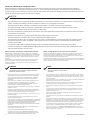
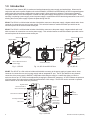
1.0 Introduction
The Service Power Inserter (SPI) is used as an interface between the power supply and coaxial plant. When used in
conjunction with service power supplies such as the APP9005C, APP9015S and APP9022S, the SPI’s integrated bypass
switch helps limit plant power outages when a power supply is being serviced or replaced. During normal operation
the bypass switch is set to ON and power is routed from the power supply through the SPI to the coaxial plant. When
servicing or replacing a power supply, a service power supply is connected to the SPI and the bypass switch is set to ALT.,
allowing the service power supply to power the plant through the SPI.
SPI-20: The SPI-20 is a 20A unit that includes a black/white connector to the power supply, a bypass switch and a Jones
connector for connection to a service power supply. This unit also features a coaxial termination port which can be
secured in place via the seizure screw access port.
SPI-25: The SPI-25 is a 25A unit that includes a black/white connector to the power supply, a bypass switch and a red/
white connector for connection to a service power supply. This unit also features a coaxial termination port which can be
secured in place via the seizure screw access port.
SPI-RF
AUX
MAIN
AC OUPUT
TEST POINT
RF
IN/
OUT
BLACK
MAIN
WHITE
GND
GRND
AUX
AUX MAIN
SURGE PROTECTOR
EQUIPPED
LEVEL
PAD
SCREW
ACCESS
Fig. 1-4, SPI-RF
Rear
Power Source Indicators
AC Output Test Point
RF In / Out
Jones Connector to
Service Power Supply
Coaxial
Termination
Seizure
Screw
Access
Onboard
Attenuation
Nut
Black / White
Connector to
Power Supply
ALT.
ON
ALT.
ON
Fig. 1-1, SPI-20 Fig. 1-3, SPI-25Fig. 1-2, SPI-20 and SPI-25 Rear
Jones Connector to
Service Power Supply
Black / White Connector to
Power Supply
Coaxial Termination
Seizure Screw Access Seizure Screw Access
Nut
Bypass Switch
Bypass Switch
Black / White
Connector to
Power Supply
Red / White
Connector to Service
Power Supply
Bypass Switch
SPI-RF: The SPI-RF is a 20A unit that includes a black/white connector to the power supply, a bypass switch, Jones
connector for connection to a service power supply and an integrated RF port. The RF port allows for easy network
connection of the power supply’s DOCSIS
®
transponder eliminating the need for a coaxial drop being run into the
enclosure from a tap. RF levels can be adjusted by changing the onboard RF attenuator. An LED indicates the presence
of primary power, and a test point provides fast measurement of AC voltage. The SPI-RF can be removed or replaced
without removal of the main cable entry assembly.

7745-997-C0-001 Rev. B (02/2021)
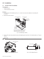
3. Hold the SPI in place using channel lock pliers while tightening the nut (see Fig. 2-3 for hardware stack up). Torque to
130 in-lb.
2.0 Installation
2.1 SPI-20 and SPI-25 Installation
Tools Required
• Channel lock pliers
• 1" torque wrench set to 130 in-lb
Procedure
1. Locate opening for SPI installation (see Fig. 2-1). A knockout is reserved for installation of a secondary SPI
(if required).
2. Remove lid from the enclosure.
*If the SPI is mounted in the location at the top
of the enclosure, the SPI must be mounted
vertically to allow space for other hardware.
RF SPI Mounting
Location
Secondary
SPI Mounting
Location
Primary SPI Mounting
Location
Optional
Locations*
(if needed)
Fig. 2-1, SPI Mounting Locations
Fig. 2-2, Channel Lock Plier Locations
Attach Channel Lock
Pliers
Fig. 2-3, SPI Hardware Stack Up
Plug
Enclosure Wall
Nut
For proper operation, the SPI must be securely bonded to the enclosure.
NOTICE:

8 745-997-C0-001 Rev. B (02/2021)
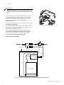
2.0 Installation
Fig. 2-5, Pole and Ground Mount Enclosure Installation (SPI-20 & SPI-25)
Power
Inserter
SPI
ALT. ON
Enclosure
RF
AC
AC
Power Supply
DOCSIS Transponder
TAP
Fig. 2-4, SPI Installation
4. Verify the bypass switch is in the A LT. position. Connect
SPI to power supply’s Output 1 connector. (For wiring
instructions, refer to the corresponding power supply
technical manual which can be downloaded at
www.alpha.com.)
5. Connect the second isolated load / auxiliary load (i.e., fan)
to the Output 2 connector.
6. Connect the coupler cable to the coaxial cable termination
port on the back of the SPI and secure in place via the
seizure screw. Torque to 25 in-lb
7. Turn on AC breaker (located on enclosure) and verify
correct (per unit’s nameplate voltage) utility voltage at
outlet; if correct, plug in line cord to the utility outlet.
8. Turn the power supply battery breaker ON.
9. Toggle bypass switch to ON.
When installing a SPI, use a power inserter to
ensure only AC is passed from the plant to the
SPI.
NOTICE:

9745-997-C0-001 Rev. B (02/2021)
2.2 SPI-RF Installation
Tools Required
• Channel lock pliers
• 1" torque wrench set to 130 in-lb
Procedure
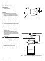
1. Locate opening for SPI-RF installation
(see Fig. 2-1). A knockout is reserved for
installation of a secondary SPI (if required).
2.0 Installation
Directional
Coupler
Enclosure
RF
AC
Power Supply
Original cable carries AC
and NMS signals
SPI-RF
DOCSIS Transponder
Fig. 2-7, Pole and Ground Mount Enclosure Installation (SPI-RF)
Fig. 2-6, SPI-RF Hardware Stack Up
2. Remove lid from enclosure.
3. Hold the SPI-RF in place using channel lock
pliers while tightening the nut. Torque to
130 in-lb.
4. Verify the bypass switch is in the A LT.
position.
5. Connect SPI-RF to the power supply’s Output
1 connector. (For wiring instructions, refer
to the corresponding power supply technical
manual which can be downloaded at
www.alpha.com.)
6. Connect the SPI-RF to the power supply
transponder via the RF In / Out port with a
coaxial RF cable.
7. Connect the coupler cable to the coaxial
cable termination port on the back of the SPI-
RF and secure in place via the seizure screw.
Torque to 25 in-lb.
8. Turn on AC breaker (located on enclosure)
and verify correct (per unit’s nameplate
voltage) utility voltage at outlet; if correct,
plug in line cord to the utility outlet.
9. Turn the power supply battery breaker ON.
10. Toggle bypass switch to ON.
Plug
Enclosure Wall
Nut
When installing a SPI-RF, use of
a directional coupler is required to
allow both RF & AC to pass from the
plant to the SPI-RF.
NOTICE:

Alpha Technologies Services, Inc. | 3767 Alpha Way, Bellingham, WA 98226, USA
Tel.: Toll Free North America: +1 800 322 5742 | Outside US: +1 360 647 2360 | Technical Support: +1 800 863 3364
For more information visit our website at: www.alpha.com
© 2021 Alpha Technologies Services, Inc. All Rights Reserved. Trademarks and logos are the property of Alpha
Technologies Services, Inc. and its aliates unless otherwise noted. Subject to revisions without prior notice. E.&O.E.
DOCSIS is a registered trademark of Cable Television Laboratories, Inc.
745-997-C0-001, Rev. B (02/2021)
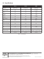
3.0 Specications
SPI-20 SPI-25 SP-RF
Part Number 020-019-31-006 021-029-21-003 021-080-20-001
Parameter Passband N/A N/A 5 to 862MHz
Flatness N/A N/A ±0.5dB
Through Loss
@ 862MHz
@ 5MHz
N/A N/A
<1.25dB
<0.5dB
Manual Control
SXP PAD
N/A N/A 0 to 20dB
Return Loss Input N/A N/A 16dB
Output 89VAC 89VAC 89VAC
AC Input Voltage 89VAC 89VAC 60 to 90VAC
AC Bypass Current (Max) 20A 25A 20A
HUM Modulation @ 15A N/A N/A -70dBc
EMI N/A N/A -110dBc
Weight 0.5lb / 0.45kg 0.5lb / 0.45kg 1.25lb / 0.83kg
Dimensions (L×W×H)
4.50" × 2.92" × 1.81"
114.30mm × 74.17mm × 45.97mm
4.50" × 2.92" × 1.81"
114.30mm × 74.17mm × 45.97mm
8.25" × 4.00" × 1.20"
209.55mm × 101.60mm × 30.48mm
Operating Temperature
-40 to 131°F
-40 to 55°C
-40 to 131°F
-40 to 55°C
-40 to 131°F
-40 to 55°C
Table 3-1, Specications
-
 1
1
-
 2
2
-
 3
3
-
 4
4
-
 5
5
-
 6
6
-
 7
7
-
 8
8
-
 9
9
-
 10
10


em outras línguas
- español: Alpha SPI-RF Guía de instalación
- français: Alpha SPI-RF Guide d'installation
- English: Alpha SPI-RF Installation guide
Artigos relacionados
Outros documentos
-
CAME PXIT0132 Guia de instalação
-
Canon CanoScan 4200F Manual do usuário
-
SOYO AVRO 3002 Manual do usuário
-
Weller SPI 81 Operating Instructions Manual
-
-
Topcom Deskmaster 4100 Manual do proprietário
-
ESAB m3® Plasma EPP-362 Plasma Power Source Manual do usuário