A página está carregando...

Intelligent Broadband UPS™ Technical Manual
XM3.1-HP Series
Effective: January 2021

2
017-950-B0-001, Rev. B (01/2021)
XM3.1-HP Series Intelligent Broadband UPS
™
Technical Manual
017-950-B0-001, Rev. B
Effective Date: January 2021
©
2021 by Alpha Technologies Services, Inc.
Disclaimer
Images contained in this manual are for illustrative purposes only. These images may not match your installation.
Operator is cautioned to review the drawings and illustrations contained in this manual before proceeding. If there are
questions regarding the safe operation of this powering system, please contact Alpha Technologies Services, Inc. or your
nearest Alpha
®
representative.
Alpha shall not be held liable for any damage or injury involving its enclosures, power supplies, generators, batteries or
other hardware if used or operated in any manner or subject to any condition not consistent with its intended purpose or is
installed or operated in an unapproved manner or improperly maintained.
Notice of FCC Compliance
Per FCC 47 CFR 15.21:
Changes or modications not expressly approved by the party responsible for compliance could void the user’s authority to
operate the equipment.
Per FCC 47 CFR 15.105:
This equipment has been tested and found to comply with the limits for a Class A digital device, pursuant to part 15 of the
FCC Rules. These limits are designed to provide reasonable protection against harmful interference when the equipment
is operated in a commercial environment. This equipment generates, uses and can radiate radio frequency energy and, if
not installed and used in accordance with the instruction manual, may cause harmful interference to radio communications.
Operation of this equipment in a residential area is likely to cause harmful interference in which case the user will be required
to correct the interference at their own expense.
Contact Information
Sales information and customer service in USA
(7AM to 5PM, Pacic Time):
Complete technical support in USA
(7AM to 5PM, Pacic Time or 24/7 emergency support):
Sales information and technical support in Canada:
Website:
+1 800 863 3364
+1 888 462 7487
www.alpha.com
+1 800 322 5742

3
017-950-B0-001, Rev. B (01/2021)
Table of Contents
XM3.1-HP Safety & Compliance Notes . . . . . . . . . . . . . . . . . . . . . . . . . . . . . . . 9
1.0 Introduction . . . . . . . . . . . . . . . . . . . . . . . . . . . . . . . . . . . . . . . . . 17
1.1 Alpha
®
XM3.1-HP Intelligent Broadband UPS. . . . . . . . . . . . . . . . . . . . . . . . 17
1.2 Theory of Operation . . . . . . . . . . . . . . . . . . . . . . . . . . . . . . . . . . . . . 18
1.2.1 AC (Line) Operation . . . . . . . . . . . . . . . . . . . . . . . . . . . . . . . . . . 18
1.2.2 Standby Operation. . . . . . . . . . . . . . . . . . . . . . . . . . . . . . . . . . . 18
1.2.3 Charger Modes of Operation . . . . . . . . . . . . . . . . . . . . . . . . . . . . . 19
1.2.4 Output Voltage Modes of Operation . . . . . . . . . . . . . . . . . . . . . . . . . . 24
1.3 Alpha
®
XM3.1-HP Broadband UPS Layout . . . . . . . . . . . . . . . . . . . . . . . . . 25
1.3.1 Front and Side Panel Connectors . . . . . . . . . . . . . . . . . . . . . . . . . . . 26
1.3.2 Smart AlphaGuard™. . . . . . . . . . . . . . . . . . . . . . . . . . . . . . . . . . 27
1.3.3 Alpha
®
Dual Output Controller (AlphaDOC) . . . . . . . . . . . . . . . . . . . . . . 28
1.3.4 Inverter Module Overview . . . . . . . . . . . . . . . . . . . . . . . . . . . . . . . 30
1.3.5 Communications Module . . . . . . . . . . . . . . . . . . . . . . . . . . . . . . . 31
2.0 Installation . . . . . . . . . . . . . . . . . . . . . . . . . . . . . . . . . . . . . . . . . . 32
2.1 Installation Procedure . . . . . . . . . . . . . . . . . . . . . . . . . . . . . . . . . . . . 32
2.1.1 Pre-installation Inspection . . . . . . . . . . . . . . . . . . . . . . . . . . . . . . . 32
2.1.2 Internal Security Screw Kit Installation. . . . . . . . . . . . . . . . . . . . . . . . . 32
2.2 XM3.1-HP Start-Up Procedure . . . . . . . . . . . . . . . . . . . . . . . . . . . . . . . 34
2.2.1 Parts and Connections. . . . . . . . . . . . . . . . . . . . . . . . . . . . . . . . . 34
2.2.2 Battery Installation Options and Wiring Diagram . . . . . . . . . . . . . . . . . . . 35
2.2.3 63/89VAC Output Voltage Reconguration Procedure . . . . . . . . . . . . . . . . 39
2.2.4 Optional Smart AlphaGuard . . . . . . . . . . . . . . . . . . . . . . . . . . . . . . 40
2.2.5 Optional N+1 Congurations. . . . . . . . . . . . . . . . . . . . . . . . . . . . . . 41
2.2.6 DOCSIS Communications Module. . . . . . . . . . . . . . . . . . . . . . . . . . . 43
2.2.7 SFP Optical Connection . . . . . . . . . . . . . . . . . . . . . . . . . . . . . . . . 45
2.2.8 Tamper Interface. . . . . . . . . . . . . . . . . . . . . . . . . . . . . . . . . . . . 46
2.2.9 Environmental Connector . . . . . . . . . . . . . . . . . . . . . . . . . . . . . . . 46
2.2.10 Power Module Conguration and Installation Procedure . . . . . . . . . . . . . . . 47
2.2.11 Local Verication of DOCSIS Transponder . . . . . . . . . . . . . . . . . . . . . . 50
2.2.12 Web Interface . . . . . . . . . . . . . . . . . . . . . . . . . . . . . . . . . . . . . 51
2.2.13 Remote Web Server Access . . . . . . . . . . . . . . . . . . . . . . . . . . . . . . 53
2.2.14 Web Interface Security Levels . . . . . . . . . . . . . . . . . . . . . . . . . . . . . 54
2.2.15 Navigating the Web Pages . . . . . . . . . . . . . . . . . . . . . . . . . . . . . . 56
3.0 Operation. . . . . . . . . . . . . . . . . . . . . . . . . . . . . . . . . . . . . . . . . . . 69
3.1 Start-Up and Test . . . . . . . . . . . . . . . . . . . . . . . . . . . . . . . . . . . . . . 69
3.1.1 Self Test Operation . . . . . . . . . . . . . . . . . . . . . . . . . . . . . . . . . . 69
3.2 Using the Smart Display . . . . . . . . . . . . . . . . . . . . . . . . . . . . . . . . . . . 70
3.3 Smart Display Menus . . . . . . . . . . . . . . . . . . . . . . . . . . . . . . . . . . . . 71
3.3.1 Power Information and Conguration . . . . . . . . . . . . . . . . . . . . . . . . . 72
3.3.2 Battery Information and Conguration . . . . . . . . . . . . . . . . . . . . . . . . . 73
3.3.3 Communication Information and Conguration . . . . . . . . . . . . . . . . . . . . 74
3.3.4 Alpha
®
Applications Information and Conguration . . . . . . . . . . . . . . . . . . 78
3.4 AlphaAPPs Overview . . . . . . . . . . . . . . . . . . . . . . . . . . . . . . . . . . . . 79
3.4.1 Display Structure. . . . . . . . . . . . . . . . . . . . . . . . . . . . . . . . . . . . 79
3.4.2 Applications . . . . . . . . . . . . . . . . . . . . . . . . . . . . . . . . . . . . . . 81

4
017-950-B0-001, Rev. B (01/2021)
Table of Contents
3.5 Active Alarms . . . . . . . . . . . . . . . . . . . . . . . . . . . . . . . . . . . . . . . . 90
3.5.1 Menu Structure/Navigation (from Active Alarms Screen) . . . . . . . . . . . . . . . 91
3.5.2 PWR Alarms . . . . . . . . . . . . . . . . . . . . . . . . . . . . . . . . . . . . . . 92
3.5.3 BATT Alarms. . . . . . . . . . . . . . . . . . . . . . . . . . . . . . . . . . . . . . 93
3.5.4 COMM Alarms . . . . . . . . . . . . . . . . . . . . . . . . . . . . . . . . . . . . . 94
3.5.5 APP Alarms . . . . . . . . . . . . . . . . . . . . . . . . . . . . . . . . . . . . . . 94
3.6 Smart Display Glossary . . . . . . . . . . . . . . . . . . . . . . . . . . . . . . . . . . . 94
3.7 Automatic Performance Test . . . . . . . . . . . . . . . . . . . . . . . . . . . . . . . . 98
3.8 Providing Power via Portable Generator or Inverter. . . . . . . . . . . . . . . . . . . . . 99
3.8.1 DC Powering. . . . . . . . . . . . . . . . . . . . . . . . . . . . . . . . . . . . . . 99
3.8.2 AC Powering. . . . . . . . . . . . . . . . . . . . . . . . . . . . . . . . . . . . . . 99
3.8.3 Using a Truck-mounted Inverter or Generator . . . . . . . . . . . . . . . . . . . . .100
3.9 Resumption of Utility Power . . . . . . . . . . . . . . . . . . . . . . . . . . . . . . . . .101
4.0 Maintenance . . . . . . . . . . . . . . . . . . . . . . . . . . . . . . . . . . . . . . . . . 102
4.1 Safety Precautions . . . . . . . . . . . . . . . . . . . . . . . . . . . . . . . . . . . . . 102
4.2 Required Tools and Equipment . . . . . . . . . . . . . . . . . . . . . . . . . . . . . . . 102
4.3 Power Supply System Maintenance. . . . . . . . . . . . . . . . . . . . . . . . . . . . .103
4.3.1 Preparing for Maintenance. . . . . . . . . . . . . . . . . . . . . . . . . . . . . . .103
4.3.2 Periodic Maintenance Tasks . . . . . . . . . . . . . . . . . . . . . . . . . . . . . .103
4.3.3 MOV Board Replacement . . . . . . . . . . . . . . . . . . . . . . . . . . . . . . . 106
4.4 PM Certication Report . . . . . . . . . . . . . . . . . . . . . . . . . . . . . . . . . . . 107
5.0 Shut Down . . . . . . . . . . . . . . . . . . . . . . . . . . . . . . . . . . . . . . . . . . 109
6.0 Specifications . . . . . . . . . . . . . . . . . . . . . . . . . . . . . . . . . . . . . . . . 110
6.1 Specications (Alpha XM3.1-HP Broadband UPS North American Models) . . . . . . . . 110
6.2 Specications (Alpha XM3.1-HP Broadband UPS International Models) . . . . . . . . . . 111
6.3 Safety and EMC Compliance . . . . . . . . . . . . . . . . . . . . . . . . . . . . . . . . 112
6.4 System Options . . . . . . . . . . . . . . . . . . . . . . . . . . . . . . . . . . . . . . . 112
6.5 Return and Repair Information . . . . . . . . . . . . . . . . . . . . . . . . . . . . . . . 113
6.6 Common Parts for XM3.1-HP . . . . . . . . . . . . . . . . . . . . . . . . . . . . . . . . 113
6.7 XM3.1-HP Block Diagram . . . . . . . . . . . . . . . . . . . . . . . . . . . . . . . . . . 114
7.0 Safety & Compliance Notes (Translations) . . . . . . . . . . . . . . . . . . . . . . . . 115
7.1 Safety Notes (German) . . . . . . . . . . . . . . . . . . . . . . . . . . . . . . . . . . . 115
7.2 Safety Notes (Spanish) . . . . . . . . . . . . . . . . . . . . . . . . . . . . . . . . . . . 123
7.3 Safety Notes (Portuguese) . . . . . . . . . . . . . . . . . . . . . . . . . . . . . . . . . 131
7.4 Safety Notes (French) . . . . . . . . . . . . . . . . . . . . . . . . . . . . . . . . . . . .139

5
017-950-B0-001, Rev. B (01/2021)
Figures
Typical 120 VAC Service Entrance Wiring ............................................................................................................................13
Typical 120 VAC 20A Receptacle Wiring, 5-20R (p/n 531-006-19) ......................................................................................13
Typical 240 VAC 15A Receptacle Wiring, 6-15R (p/n 531-004-19) ......................................................................................13
Typical 240 VAC 60 Hz Service Entrance Wiring .................................................................................................................14
Typical 230 VAC 50 Hz Service Entrance Wiring .................................................................................................................14
SPI Location .........................................................................................................................................................................15
Communications Grounding .................................................................................................................................................16
Fig. 1-1, Alpha XM3.1-HP Intelligent Broadband UPS .........................................................................................................17
Fig. 1-2, 3-Stage Charger Modes .........................................................................................................................................20
Fig. 1-3, 4-Stage Charger Modes .........................................................................................................................................21
Fig. 1-4, 4-Stage Charger Modes for XTV Batteries.............................................................................................................22
Fig. 1-5, 5-Stage Charger Modes .........................................................................................................................................23
Fig. 1-6, Front Panel, XM3.1-HP Power Supply ...................................................................................................................25
Fig. 1-7, Side Panel, XM3.1-HP Power Supply ....................................................................................................................26
Fig. 1-8, Detail View, Front Panel Connections and Indicators ............................................................................................26
Fig. 1-9, SAG Front Panel ....................................................................................................................................................27
Fig. 1-10, Inverter Module Connections ...............................................................................................................................30
Fig. 1-11, Communications Module ......................................................................................................................................31
Fig. 2-1, Required Materials .................................................................................................................................................33
Fig. 2-2, Security Screw Mounting Location .........................................................................................................................33
Fig. 2-3, Power Supply/Enclosure Shelf Security Screw Stack Up ......................................................................................33
Fig. 2-4, Installation of XM3.1-HP ........................................................................................................................................34
Fig. 2-5, Placement of Battery Spacer Clips (for domestic and international 36V battery strings) ....................................... 35
Fig. 2-6, Battery Wiring Diagram (w/ embedded SAG option depicted) ...............................................................................35
Fig. 2-7, Precision Temperature Sensor (PTS), p/n 746-331-20 ..........................................................................................35
Fig. 2-8, Dual Battery String Wiring Diagram (w/ embedded SAG Harness depicted) .........................................................36
Fig. 2-9, Multiple Battery String Wiring Diagram (w/ embedded SAG Harness depicted) ....................................................37
Fig. 2-10, Wiring diagram, 8-battery Parallel Conguration..................................................................................................38
Fig. 2-11, Battery Terminal Bolt Stack-up .............................................................................................................................39
Fig. 2-12, Fuse Bolt Stack-up ...............................................................................................................................................39
Fig. 2-13, Voltage Terminal Location and Wire Position .......................................................................................................39
Fig. 2-14, Inverter Module Screw Locations .........................................................................................................................40
Fig. 2-15, Installing the SAG.................................................................................................................................................40
Fig. 2-17, N+1 Conguration ................................................................................................................................................41
Fig. 2-16, SPI, Output and SAG Harness Connections ........................................................................................................41
Fig. 2-18, Dual Redundancy N+1 Conguration ...................................................................................................................42
Fig. 2-19, Active Alarm Screen .............................................................................................................................................42
Fig. 2-20, N+1 In Use Alarm Screen .....................................................................................................................................42
Fig. 2-21, DOCSIS Communications Module Front Panel Connections ..............................................................................43
Fig. 2-22, Installing SFP and Fiber Connection .................................................................................................................... 45
Fig. 2-23, Active Alarm Screen .............................................................................................................................................48
Fig. 2-24, Enter Battery Date Code ......................................................................................................................................48

6
017-950-B0-001, Rev. B (01/2021)
Fig. 2-25, Enter Battery MHOs Reading ...............................................................................................................................48
Fig. 2-26, Select Language in PWR CNFG Menu ................................................................................................................ 49
Fig. 2-27, COMM Menu Options...........................................................................................................................................50
Fig. 2-28, DOCSIS 3.1 CMOA Web Page ............................................................................................................................51
Fig. 2-29, Local Area Connection Properties Screen, Windows 10 ......................................................................................52
Fig. 2-30, Internet Protocol (TCP/IP) Properties Screen, Windows 10.................................................................................52
Fig. 2-31, Web Server Home Page ......................................................................................................................................53
Fig. 2-32, CMOA Series Navigation Bar ...............................................................................................................................56
Fig. 2-33, Power Supply Web Page .....................................................................................................................................57
Fig. 2-34, Batteries Web Page .............................................................................................................................................57
Fig. 2-35, Environmental I/O Web Page ............................................................................................................................... 58
Fig. 2-36, Components Web Page .......................................................................................................................................58
Fig. 2-37, DOCSIS Web Page .............................................................................................................................................. 59
Fig. 2-38, RF Attenuation Web Page .................................................................................................................................... 60
Fig. 2-39, SFP Web Page .....................................................................................................................................................60
Fig. 2-40, Ethernet Web Page ..............................................................................................................................................61
Fig. 2-41, System Data Web Page .......................................................................................................................................61
Fig. 2-42, SNMP Web Page .................................................................................................................................................62
Fig. 2-43, Alarms Web Page .................................................................................................................................................62
Fig. 2-43, Alarms Web Page, continued ...............................................................................................................................63
Fig. 2-43, Alarms Web Page, continued ...............................................................................................................................64
Fig. 2-44, Utility Power Web Page ........................................................................................................................................64
Fig. 2-45, Power Supply Events Web Page .........................................................................................................................65
Fig. 2-46, Power Supply Conguration Web Page ...............................................................................................................65
Fig. 2-47, Battery Events Web Page ....................................................................................................................................66
Fig. 2-48, Modem Log Web Page .........................................................................................................................................66
Fig. 2-49, Alarm Log Web Page ...........................................................................................................................................67
Fig. 2-50, Microreections Web Page ..................................................................................................................................67
Fig. 2-51, Firmware Update Web Page ................................................................................................................................68
Fig. 3-1, Operation Normal Display Screen ..........................................................................................................................70
Fig. 3-2, Navigating Through Menu Screens ........................................................................................................................ 70
Fig. 3-3, Smart Display Menus .............................................................................................................................................71
Fig. 3-4, Power Information and Conguration Menu Options .............................................................................................72
Fig. 3-5, Battery Information and Conguration Menu Options ............................................................................................73
Fig. 3-8, RF - GENERAL Menu Options ............................................................................................................................... 74
Fig. 3-6, Communication Information and Conguration Menu Options...............................................................................74
Fig. 3-7, COMM - FAULT Menu Screen ...............................................................................................................................74
Fig. 3-9, RF - DIAGNOSTICS Menu Screen ........................................................................................................................75
Fig. 3-10, RF - DIAGNOSTICS Menu Options .....................................................................................................................75
Fig. 3-11, SFP - GENERAL Menu Options ...........................................................................................................................76
Fig. 3-12, SFP - DIAGNOSTICS Menu Options ...................................................................................................................76
Fig. 3-13, TRANSPONDER Menu Screen ...........................................................................................................................77
Figures

7
017-950-B0-001, Rev. B (01/2021)
Fig. 3-14, TRANSPONDER Menu Options ..........................................................................................................................77
Fig. 3-15, AlphaAPPs Menu Options .................................................................................................................................... 78
Fig. 3-16, Technician ID Screen ...........................................................................................................................................79
Fig. 3-17, Technician ID Log Screen ....................................................................................................................................79
Fig. 3-18, AlphaAPPs Main Menu Screen ............................................................................................................................79
Fig. 3-19, AlphaAPPs Menu Options .................................................................................................................................... 80
Fig. 3-20, Conguration History ............................................................................................................................................81
Fig. 3-21, Event Log Screen ................................................................................................................................................. 82
Fig. 3-22, Battery Manufacture Date Screen ........................................................................................................................83
Fig. 3-23, Battery Mhos Screen ............................................................................................................................................ 84
Fig. 3-24, Logged Battery Mhos Screen ...............................................................................................................................84
Fig. 3-25, Battery History ...................................................................................................................................................... 85
Fig. 3-26, Utility Performance Menu Options........................................................................................................................86
Fig. 3-27, Outage History .....................................................................................................................................................87
Fig. 3-28, Battery Health.......................................................................................................................................................88
Fig. 3-29, Battery Run Time..................................................................................................................................................88
Fig. 3-30, Active Drop ...........................................................................................................................................................89
Fig. 3-31, Active Alarm Table ................................................................................................................................................90
Fig. 3-32, Sample Active Alarm Display, PWR Menu ...........................................................................................................91
Fig. 3-33, Sample Active Alarm Display, BATT Menu ...........................................................................................................91
Fig. 3-34, Sample Active Alarm Display, COMM Menu ........................................................................................................91
Fig. 4-1, XM3.1-HP System Components ..........................................................................................................................104
Fig. 4-2, Removing the Transformer Module Cover ...........................................................................................................106
Fig. 4-3, MOV Board Location ............................................................................................................................................106
Fig. 4-4, MOV Board Model ................................................................................................................................................ 106
Fig. 4-5, PM Certication Report, Page 1 ...........................................................................................................................107
Fig. 4-6, PM Certication Report, Page 2 ...........................................................................................................................108
Fig. 5-1, Emergency Shutdown ..........................................................................................................................................109
Fig. 6-1, XM3.1-HP Block Diagram ....................................................................................................................................114
Fig. 7-1, Typische Netzanschlussverdrahtung für 120 V Wechselstrom ............................................................................ 119
Fig. 7-2, Typische Steckdosenverdrahtung für 120 V/20 A Wechselstrom, 5-20R (Teile-Nr. 531-006-19) ......................... 119
Fig. 7-3, Typische Steckdosenverdrahtung für 240 V/15 A Wechselstrom, 6-15R (Teile-Nr. 531-004-19) ......................... 119
Fig. 7-4, Typische Netzanschlussverdrahtung für 240 V/60 Hz Wechselstrom .................................................................. 120
Fig. 7-5, Typische Netzanschlussverdrahtung für 230 V/50 Hz Wechselstrom .................................................................. 120
Fig. 7-6, SPI-Standort ......................................................................................................................................................... 121
Fig. 7-7, Kommunikationserdung........................................................................................................................................122
Fig. 7-8, Cableado típico de entrada de servicio de 120 VCA ............................................................................................127
Fig. 7-9, Cableado típico de receptáculo de 120 VCA 20A, 5-20R (p/n 531-006-19) ........................................................127
Fig. 7-10, Cableado típico de receptáculo de 240 VCA 15A, 6-15R (p/n 531-004-19) ......................................................127
Fig. 7-11, Cableado típico de entrada de servicio de 240 VCA 60 Hz ................................................................................128
Fig. 7-12, Cableado típico de entrada de servicio de 230 VCA 50 Hz ...............................................................................128
Fig. 7-13, Ubicación del SPI ...............................................................................................................................................129
Figures

8
017-950-B0-001, Rev. B (01/2021)
Tables
Circuit Breakers and Service Disconnects ...........................................................................................................................12
Table 1-1, Low Battery Cutoff (EOD) ....................................................................................................................................19
Table 1-2, Charger Modes of Operation ...............................................................................................................................19
Table 1-3, Smart AlphaGuard LEDs Behavior ......................................................................................................................27
Table 1-4, Duration of Load ..................................................................................................................................................28
Table 2-1, Rx/Tx LEDs Behavior ..........................................................................................................................................44
Table 2-3, OIDs for Usernames and Passwords ..................................................................................................................54
Table 2-3, OIDs for Usernames and Passwords, continued ................................................................................................. 55
Table 3-1, AC Output ............................................................................................................................................................69
Table 3-2, Main Menu Functions ..........................................................................................................................................70
Table 3-3, Logged Events and Alarms ..................................................................................................................................82
Table 3-4, PWR Alarms: Classications, Causes and Corrections .......................................................................................92
Table 3-5, BATT Alarms: Classications, Causes and Corrections ......................................................................................93
Table 3-6, COMM Alarms: Classications, Causes and Corrections ....................................................................................94
Table 3-7, APP Alarms: Classications, Causes and Corrections ........................................................................................94
Table 6-1, North American Specications ........................................................................................................................... 110
Table 6-2, International Specications ................................................................................................................................ 111
Table 6-3, Product Certications Regarding Safety, EMC Compliance .............................................................................. 112
Table 6-4, XM3.1-HP Common Parts ................................................................................................................................. 113
Table 7-1, Leistungsschalter und Service-Trennschalter .................................................................................................... 118
Table 7-2, Disyuntores de circuito y desconexiones de servicio ........................................................................................126
Table 7-3, Disjuntor e Desconectores de Serviço...............................................................................................................134
Table 7-4, Disjoncteurs et sectionneurs..............................................................................................................................142
Figures
Fig. 7-14, Comunicaciones a tierra.....................................................................................................................................130
Fig. 7-15, Fiação Típica da Entrada de Serviço 120 VAC ..................................................................................................135
Fig. 7-16, Fiação Típica do Receptáculo 120 VCA 20A, 5-20R (p/n 531-006-19) ..............................................................135
Fig. 7-17, Fiação Típica do Receptáculo 240 VCA 15A, 6-15R (p/n 531-004-19) ..............................................................135
Fig. 7-18, Fiação Típica da Entrada de Serviço 240 VCA 60 Hz ........................................................................................136
Fig. 7-19, Fiação Típica da Entrada de Serviço 230 VCA 50 Hz ........................................................................................136
Fig. 7-20, Local do SPI .......................................................................................................................................................137
Fig. 7-21, Aterramento das Comunicações ........................................................................................................................138
Fig. 7-22, Câblage typique d'un branchement de 120 VCA ...............................................................................................143
Fig. 7-23, Câblage typique d'une prise de courant de 120 VCA 20 A, 5-20R (No de pièce 531-006-19) ...........................143
Fig. 7-24, Câblage typique d'une prise de courant de 240 VCA 15 A, 6-15R (No de pièce 531-004-19) ...........................143
Fig. 7-25, Câblage typique d'un branchement de 240 VCA 60 Hz .....................................................................................144
Fig. 7-26, Câblage typique d'un branchement de 230 VCA 50 Hz .....................................................................................144
Fig. 7-27, Emplacement du SPI..........................................................................................................................................145
Fig. 7-28, Mise à la terre des lignes de transmission .........................................................................................................146

9
017-950-B0-001, Rev. B (01/2021)
XM3.1-HP Safety & Compliance Notes
Review the drawings and illustrations contained in this manual before proceeding. If there are any questions regarding the
safe installation or operation of the system, contact Alpha Technologies Services, Inc. or the nearest Alpha
®
representative.
Save this document for future reference.
To reduce the risk of injury or death and to ensure the continued safe operation of this product, the following symbols have
been placed throughout this manual. Where these symbols appear, use extra care and attention.
Refer to Section 7.0, Safety & Compliance Notes (Translations) for German, Spanish, Portuguese and French safety
notes.
Sicherheitshinweise in Englisch, Spanisch, Portugiesisch und Französisch nden Sie in Abschnitt 7.0, Hinweise zur
Einhaltung der Sicherheit.
Consulte la Sección 7.0, Notas sobre Seguridad y Cumplimiento (traducciones) para ver notas sobre seguridad en
alemán, español, portugués y francés.
Consulte a Seção 7.0, Notas de Segurança e Conformidade (Traduções) para ver as notas de segurança em alemão,
espanhol, português e francês.
Veuillez vous reporter à la section 7.0, Remarques sur la sécurité et la conformité (traductions), pour lire les
remarques sur la sécurité en allemand, en espagnol, en portugais et en français.
There may be multiple warnings associated with the call out. Example:
ATTENTION provides specic regulatory/code requirements that may affect the placement of
equipment and /or installation procedures.
ATTENTION:
NOTICE provides additional information to help complete a specic task or procedure.
NOTICE:
ELECTRICAL HAZARD WARNING provides electrical safety information to PREVENT
INJURY OR DEATH to the technician or user.
WARNING! ELECTRICAL HAZARD
FUMES HAZARD WARNING provides fumes safety information to PREVENT INJURY OR
DEATH to the technician or user.
WARNING! FUMES HAZARD
FIRE HAZARD WARNING provides ammability safety information to PREVENT INJURY OR
DEATH to the technician or user.
WARNING! FIRE HAZARD
This WARNING provides safety information for both Electrical AND Fire Hazards
WARNING! ELECTRICAL & FIRE HAZARD
CAUTION provides safety information intended to PREVENT DAMAGE to material or
equipment.
CAUTION!
GENERAL HAZARD WARNING provides safety information to PREVENT INJURY OR
DEATH to the technician or user.
WARNING! GENERAL HAZARD

Safety Precautions
This power supply has been investigated by regulatory authorities for use in various Alpha enclosures. If a non-Alpha
enclosure is being used, it is the operator or installer's responsibility to ensure the combination conforms to your local
regulatory requirements and the power supply remains within its environmental specications.
ATTENTION:
Do not allow live battery wires to contact the enclosure chassis. Shorting battery wires can result in a re or
possible explosion.
WARNING! ELECTRICAL & FIRE HAZARD
• In the event of a short-circuit, batteries present a risk of electrical shock and burns from high current. Observe
proper safety precautions.
• The battery string, which provides backup power, contains dangerous energy. Only qualied personnel should
inspect or replace batteries.
• The power supply contains more than one live circuit. Even though AC voltage is not present at the input,
voltage may still be present at the output.
WARNING! ELECTRICAL HAZARD
• This equipment shall be installed by qualied service personnel only, according to the installation instructions
provided with each unit.
• This equipment is not provided with a suitable re enclosure. Intended to be installed in a suitable re enclosure
in the end installation.
• This equipment is not intended for direct outdoor installation. A suitable outdoor enclosure shall be provided in
the end installation.
• Power Supply Output is considered Hazardous Voltage Secondary (CATV).
• This equipment is intended for use in a national two wire CATV system. Line-Neutral/Ground is functional and
relies upon multipoint grounding of the end-use enclosure for safety. Acceptability of this equipment in the end-
use CATV system is to be determined by the authority having jurisdiction (AHJ).
• External circuits on the Battery, communications card and “Temp Probe” are considered ES1.
• Battery testing was conducted with the manufacturer’s recommended batteries.
• The product was tested in a branch circuit protected by a 20A circuit breaker. Additional evaluation shall be
conducted if a higher protector is to be used in the end system.
• Evaluated for use at max 60ºC ambient temperature (derating applicable), Pollution Degree 3 environment,
overvoltage category III.
• The equipment contains VDRs and gas tubes bridging insulation. Acceptability shall be determined by the
accepting AHJ.
• Evaluated for connection to a CABLE DISTRIBUTION SYSTEM with a maximum external transient overvoltage
rating of 4000Vpk.
• Verify the voltage requirements of the equipment to be protected (load), the AC input voltage to the power supply
(line) and the output voltage of the system prior to installation.
• Equip the utility service panel with a properly rated circuit breaker for use with this power supply.
• Always use proper lifting techniques whenever handling units, modules or batteries.
• If adding an external battery pack fuse, select a value whose opening characteristics are higher than the DC
circuit breaker provided in your unit.
CAUTION!
The following sections contain important safety information that must be followed during the installation and maintenance
of the equipment and batteries. Read all of the instructions before installing or operating the equipment, and save this
manual for future reference.
10 017-950-B0-001, Rev. B (01/2021)

Battery Safety Notes
Battery Maintenance Guidelines
• Always wear eye protection, rubber gloves, and a protective vest when working near
batteries. To avoid battery contact, remove all metallic objects, (such as rings or watches).
• Prior to handling the batteries, touch a grounded metal object to dissipate any static charge
that may have developed on your body.
• Use tools with insulated handles, do not rest any tools on top of batteries.
• Use special caution when connecting or adjusting battery cabling. An improperly or
unconnected battery cable can make contact with an unintended surface that can result in
arcing, re, or a possible explosion.
WARNING! ELECTRICAL HAZARD
• Batteries produce explosive gases. Keep all open ames and sparks away from batteries.
• Do not charge batteries in a sealed container. Each battery should have at least 1/2 inch
(13 mm) of space between it and all surrounding surfaces to allow for convection cooling.
• All battery compartments must have adequate ventilation to prevent an accumulation
of potentially dangerous gas. Never place batteries in a sealed enclosure. Ensure all
enclosure vents and lters are clean and free of debris.
WARNING! FIRE HAZARD
• Inspect each battery during every maintenance check. Replace or repair batteries if any of the following is found:
• Signs of battery cracking, leaking or swelling.
• Signs of battery cable damage.
• Loose battery connection hardware.
• Do not attempt to remove the vents (valves) from the AlphaCell
®
broadband battery or add water. This is a
safety hazard and voids the warranty.
• A battery showing signs of cracking, leaking, or swelling should be replaced immediately by authorized
personnel.
• Always replace batteries with those of an identical type and rating. Match conductance, voltage and date
codes. Never install untested batteries.
• Always follow battery manufacturer's storage instructions.
• Apply electrical contact lubricant or grease such as NO-OX
®
grease on all exposed connections.
CAUTION!
• Any gelled or liquid emissions from a valve-regulated lead-acid (VRLA) battery contains
diluted sulfuric acid, which is harmful to the skin and eyes. Emissions are electrolytic and
are electrically conductive and corrosive.
• If any battery emission contacts the skin, wash immediately and thoroughly with water.
Follow your company’s approved chemical exposure procedures.
• Neutralize any spilled battery emission with the special solution contained in an approved spill
kit or with a solution of one pound bicarbonate of soda to one gallon of water. Report a chemical
spill using your company’s spill reporting structure and seek medical attention if necessary.
WARNING! GENERAL HAZARD
• Clean up any spilled electrolyte in accordance with all federal, state, and local regulations or codes.
• Spent or damaged batteries are environmentally unsafe. Always recycle used batteries. Refer to local codes for
proper disposal of batteries.
ATTENTION:
11017-950-B0-001, Rev. B (01/2021)

Utility Power Connection Notes
Local regulatory authorities may require the use of an approved service entrance and/or service disconnect switch when
the power supply is installed in an outdoor enclosure. Alpha enclosures have switch options. The installer may need to
provide these if using a non-Alpha enclosure.
Connecting to the utility should be performed only by qualied service personnel and in compliance with local electrical
codes. Connection to utility power must be approved by the local utility before installing the power supply.
ATTENTION:
In most cases, the following congurations qualify for service entrance use when wiring a duplex receptacle to a service
disconnect. Other codes may also apply. Always contact your local utility to verify the wiring conforms to applicable
codes.
ATTENTION:
XM3.1-HP Connections
Proper 120VAC 20A service requires the installation site to be:
• Equipped with a 120VAC duplex receptacle which provides power to the power supply and peripheral
equipment.
• Equipped with a NEMA 5-20R receptacle protected by a single-pole, 20 amp High Magnetic (HM) circuit
breaker inside the service entrance.
• Checked to NEC/CEC Code or with your local regulatory authority to verify proper wire AWG (suggested wire
gauge is #12 AWG).
• Equipped with a grounding clamp on the enclosure to facilitate dedicated grounding.
Circuit Breakers and Service Disconnects
Description
Alpha Part
Number
Square D Part Number
240V Installation - HACR (15A) 470-224-10 QO215
120V Installation - High-magnetic (20A) 470-017-10 QO120HM
2-space BBX - External Service Disconnect 020-085-10 QO2-4L70RB
8-space BBX - External Service Disconnect 020-141-10 QO8-16L100RB
Alpha enclosures are engineered to properly vent the power supply. The power supplies have been investigated by
regulatory authorities for use in various Alpha enclosures. If a non-Alpha enclosure is being used, it is the operator
or installer's responsibility to ensure the combination conforms to your local regulatory requirements and the power
supply remains within its environmental specications.
NOTICE:
In order to accommodate the high-inrush currents normally associated with the start-up of ferroresonant
transformers (400 amp, no-trip, rst-half cycle), either a “high-magnetic” or an HACR (Heating, Air Conditioning,
Refrigeration) trip breaker must be used. Do not replace these breakers with a conventional service entrance
breaker. Alpha recommends ONLY Square D breakers because of the increased reliability required in this powering
application. High-magnetic Square D circuit breakers and a BBX option (UL Listed service entrance) are available
from Alpha Technologies Services, Inc.
NOTICE:
When it is required to bond the box to a neutral plate, use the long green bonding screw provided (Alpha p/n 523-
011-10, Square D p/n 40283-371-50).
NOTICE:
12 017-950-B0-001, Rev. B (01/2021)

To Utility
Neutral (White)
Neutral Bus
Neutral (White)
LI (Black)
Copper Ground Wire
#8 AWG (Minimum)
Grounding Point
Made to Enclosure
Wall
Breaker
Copper Ground Wire
#8 AWG (Minimum)
LI (Black)
To Enclosure
Receptacle
Typical 120 VAC Service Entrance Wiring
Typical 120 VAC 20A Receptacle Wiring, 5-20R (p/n 531-006-19)
Neutral
(White)
LI
(Black)
Ground
(Green)
Typical 240 VAC 15A Receptacle Wiring, 6-15R (p/n 531-004-19)
L2
(Red)
LI
(Black)
Ground
(Green)
Utility Power Connection Notes, continued
13017-950-B0-001, Rev. B (01/2021)

Proper 240VAC 15A service requires the installation site be:
• Equipped with a 240VAC duplex receptacle to provide power to the power supply and peripheral equipment.
• Have a NEMA 6-15R receptacle that is protected by a single, 2-pole, common trip 15A circuit breaker inside
the service entrance.
• Checked to NEC/CEC Code or with your local regulatory authority to verify proper wire AWG (suggested wire
gauge is #14 AWG).
• Equipped with a grounding clamp on the enclosure to facilitate dedicated grounding.
Utility Power Connection Notes, continued
Typical 240 VAC 60 Hz Service Entrance Wiring
Typical 230 VAC 50 Hz Service Entrance Wiring
When it is required to bond the box to a neutral plate, use the long green bonding screw provided (Alpha p/n 523-
011-10, Square D p/n 40283-371-50).
NOTICE:
To Utility
LI (Black)
LI (Black)
Neutral (White)
Neutral (White)
Neutral Bus
L2 (Red)
L2 (Red)
Copper Ground Wire
#8 AWG (Minimum)
Copper Ground Wire
#8 AWG (Minimum)
Breaker
Grounding Point
Made to Enclosure
Wall
To Utility
Neutral (Blue)
Neutral Bus
Neutral (Blue)
To Enclosure
Receptacle
Copper Ground Wire
(Yellow/Green)
Copper Ground Wire
10mm2 or #8 AWG
(Minimum) (Yellow/Green)
LI (Brown)
LI (Brown)
Grounding Point Made
to Enclosure Wall
Breaker
14 017-950-B0-001, Rev. B (01/2021)

Grounding & Earth Connection Notes
In order to provide a ready, reliable source of backup power, it is necessary to connect the power supply to an effective
grounding and earthing system. This not only provides for the safety of the service personnel responsible for its operation and
maintenance, but also facilitates the proper operation and protection of the equipment within the network. Such a grounding
system provides protection with respect to operator safety, system communication and equipment protection.
Lightning strikes, grid switching or other aberrations on the power line and/or communications cable have the potential to
cause high-energy transients that can damage the powering or communications systems. The most viable method available
to protect the system from damage is to divert these unwanted high-energy transients along a low-impedance path to earth.
A low-impedance path to earth prevents these currents from reaching high voltage levels and posing a threat to equipment.
The key to the success of lightning protection is single-point grounding so the components of the grounding system appear
as a single point of uniform impedance. Two places recommended by Alpha for single-point grounding are connections
in the enclosure and connections to earth. Single-point grounding in the enclosure is achieved by bonding all electrical
connections to the enclosure, including the connection to earth, as close together on the enclosure as possible. Single-point
grounding for the connection to earth is achieved, for example by the proper bonding of the ground rods.
Safety Ground & Earth Connection
The safety ground and earth is a two-part system, comprised of the utility service and the Alpha grounding system.
1. The utility service:
As a minimum requirement for the protection of Alpha equipment, the local utility service must provide a low-
impedance path for fault current return. In addition, there must be a low impedance bonded path between the
power supply ground pin and the enclosure.
2. The Alpha grounding system:
The Alpha grounding system consists of a low-impedance connection between the enclosure and an earth
ground (located at least 6' away from the utility earth connection).
This impedance between the enclosure and earth must be 25 ohms or less at 60 hertz as measured by
Amprobe
®
Model DGC-1000 or equivalent. The measurement should be made on the wire or ground rod after
it exits the enclosure. Consult your local code or NEC 250.53.
Local soil conditions will determine the complexity of the grounding system required to meet the 25 ohm
(maximum) resistance specied above. For example, a single 8’ ground rod may be sufcient to meet
the requirement. In some cases, a more elaborate system may be required such as multiple ground rods
connected by a #6 AWG solid copper cable buried 8-12" below the surface. Where this is not possible, contact
a local grounding system expert for alternate methods that will meet the 25 ohm (maximum) specication.
All ground rod connections must be made by means of a listed grounding clamp suitable for direct burial or
exothermic welding.
Power Output Return
For proper operation, the Service Power Inserter (SPI) (Alpha p/n 020-019-31, 15A model; Alpha p/n 021-029-21, 25A
model) must be securely bonded to the enclosure.
SPI
SPI Location
15017-950-B0-001, Rev. B (01/2021)

Communications Grounding
For systems using an embedded transponder, the grounding connection is typically made either through a separate chassis
ground block bonded to the enclosure or by means of the internal mounting hardware which bonds the transponder through
the Broadband UPS power supply. Please refer to the appropriate communications product manual for installation procedures.
For communication cables, Alpha strongly recommends the use of a surge arresting device electrically bonded to the Alpha
enclosure.
Grounding and Earth Connection Notes, continued
Required
Grounded Surge Protector
(Alpha p/n 162-028-10 or equivalent)
RF Cable to Headend
Communications Grounding
Low impedance grounding is mandatory for personnel safety and critical for the proper
operation of the cable system.
WARNING! ELECTRICAL HAZARD
16 017-950-B0-001, Rev. B (01/2021)

The Intelligent Broadband UPS™ powers signal processing equipment in cable television and broadband LAN distribution
systems. The transformer module provides a critical load with current-limited regulated AC power that is free of spikes,
surges, sags and noise.
During AC line operation, AC power entering the power supply is converted into a quasi square wave and is regulated by
a ferroresonant transformer at the required output voltage. The regulated voltage is connected to the load via the output
connectors and some power is directed to the battery charger to maintain a oat charge on the batteries.
When the incoming AC line voltage signicantly deviates from normal, the Inverter Module automatically switches to
standby operation and maintains power to the load. During the switch to standby operation, energy in the module’s
ferroresonant transformer continues to supply power to the load. In standby mode, the power supply powers the load until
the battery voltage reaches a low-battery cutoff point.
When utility power returns, the transformer module waits a short time (approximately 10 to 20 seconds) for the utility
voltage and frequency to stabilize and then initiates a smooth, in phase transfer back to AC line power. Once the transfer
is complete, the battery charger recharges the batteries in preparation for the next event.
The Alpha XM3.1-HP Broadband UPS contains the following:
• Smart Display
• Hot-swappable Inverter Module
• Built-in Self Test
• Wide input voltage range
• High efciency transformer
• Communications menu with DOCSIS
®
parameters
• Optional Smart AlphaGuard™ (SAG)
• Optional factory-installed Alpha
®
Dual Output Controller
(AlphaDOC) allows the XM3.1-HP to provide programmable
current limits for two output channels.
1.0 Introduction
1.1 Alpha
®
XM3.1-HP Intelligent Broadband UPS
Fig. 1-1, Alpha XM3.1-HP Intelligent Broadband UPS
• Optional AlphaAPPs (APPS) functionality
• Via the Smart Display, the operator can
view all of the power supply’s operating
parameters.
• Troubleshooting tips automatically display
in the Alarm menu screen.
• Built-in metering circuits measure voltage
and current, without the need for external
test equipment.
The duration of battery-backed standby operation depends upon the type and number of batteries and the load on
the power supply.
NOTICE:
During a no-load start-up, the power supply may reduce output voltage to 75-80% of rated output voltage until a
load of greater than 1.5A is applied.
NOTICE:
17017-950-B0-001, Rev. B (01/2021)

18
017-950-B0-001, Rev. B (01/2021)
1.0 Introduction, Continued
1.2.2 Standby Operation
When the incoming AC line voltage drops or rises signicantly or a complete power outage occurs, the control logic’s line
monitor activates standby operation. During the transfer from AC line to standby operation, the battery powered inverter
comes online as the isolation relay switches to prevent AC power from back-feeding to the utility. The following changes
also occur within the power supply:
• The isolation relay opens to disconnect the AC line from the primary winding of the ferroresonant transformer.
• The control logic switches the inverter FETs (eld-effect transistor) on and off. This switching action converts the
DC battery current into AC current in the inverter windings of the ferroresonant transformer, providing regulated
power to the load.
• The control logic, which includes a microprocessor and other circuits to protect the inverter FETs from overcurrent
damage, monitors the condition of the batteries and the inverter during standby operation. Since a prolonged AC
line outage could severely discharge the batteries, resulting in permanent damage, the control logic disables the
inverter when the batteries drop to a predetermined cutoff voltage.
• The XM3.1-HP offers two user-selectable EOD (End of Discharge) options based on either overall string voltage
or individual battery voltage. See Table 1-1 for battery specic EOD settings. Operation is dened as follows:
• Battery String Voltage Mode which shuts off the inverter when the 36V bus voltage reaches Low Battery
Cutoff Voltage as seen at the inverter.
• Individual Battery Voltage Mode which shuts off the inverter when any battery in any string (1-4) reaches Low
Battery Cutoff Voltage.
• All units will factory default to Battery String Voltage Mode.
• Individual battery EOD will only be available (user-selectable) if individual battery voltages are being sensed
and present at logic card via the Smart AlphaGuard™.
• When set to Battery String Voltage Mode the “Low Battery Cutoff” (EOD) is not user adjustable from the
default. See Table 1-1 for more information.
• When set to individual Battery Voltage Mode the “Low Battery Cutoff” (EOD) will automatically set to default
values based on battery type (see Table 1-1). A secondary option is then offered to the user for manually
programming the “Low Battery Cutoff” (EOD), regardless of battery type, within the range 1.65 to 1.80 V/C.
1.2 Theory of Operation
1.2.1 AC (Line) Operation
During AC Line operation, utility power is routed into the primary winding of the ferroresonant transformer through the
contacts of the line isolation relay. Simultaneously, in the inverter, power is directed to the rectier circuitry providing power
for the control circuitry. The bidirectional inverter also serves as a battery charger during line operation. The ferroresonant
transformer and an AC capacitor form the resonant tank circuit, which provides excellent noise and spike attenuation, output
short-circuit current-limiting, and output voltage regulation. The ferroresonant transformer produces a quasi square wave
output which resembles a rounded square wave.
When measuring the output voltage of ferroresonant transformers, use only a true RMS AC voltmeter.
Non-RMS reading meters are calibrated to respond to pure sine waves and do not provide an accurate reading
when measuring quasi square wave output.
NOTICE:

19017-950-B0-001, Rev. B (01/2021)
1.0 Introduction, Continued
• When set to Individual Battery Voltage Mode, if individual battery voltage is lost, the unit automatically reverts
back to Battery String Voltage Mode and "Low Battery Cutoff” (EOD) will revert back to default value based on
battery type.
• When acceptable AC line voltage returns, the power supply returns to AC line operation after a 10 to 20 second
lag. This delay lets the AC line voltage and frequency stabilize before the control logic phase-locks the inverter’s
output to the utility input. The control logic then de-energizes the isolation relay, reconnects the AC line to the
primary of the ferroresonant transformer and disables (turns off) the inverter. This results in a smooth, in-phase
transfer back to utility power without interruption of service to the load. The battery charging circuit then activates
to recharge the batteries in preparation for the next power outage.
1.2.3 Charger Modes of Operation
Table 1-1, Low Battery Cutoff (EOD)
Table 1-2, Charger Modes of Operation
HP Batteries GXL Batteries XTV Batteries
OTHER
Batteries
Fixed Fixed Fixed Fixed
String Low Battery
Cutoff (EOD)
30.6 VDC
(1.70 V/C)
31.5 VDC
(1.75 V/C)
31.5 VDC
(1.75 V/C)
31.5 VDC
(1.75 V/C)
Individual Low Battery
Cutoff
(EOD)
Default Minimum Maximum
HP Batteries
10.2 VDC
(1.70 V/C)
9.9 VDC
(1.65 V/C)
10.8 VDC
(1.80 V/C)
GXL Batteries
10.5 VDC
(1.75 V/C)
XTV Batteries
10.5 VDC
(1.75 V/C)
OTHER Batteries
10.5 VDC
(1.75 V/C)
AlphaCell
®
Batteries OTHER Batteries
HP GXL XTV Default Minimum Maximum
Float V/C 2.25 2.27 2.25 2.27 2.10 2.35
Accept V/C 2.35 2.40 2.35 2.40 2.20 2.45
Automatic 30-Minute
Refresh On/Off
ON ON OFF OFF OFF OFF
Manual 24-Hour
Refresh On/Off
OFF
(Programmable)
OFF
(Programmable)
OFF
(Programmable)
OFF
(Programmable)
OFF ON
Refresh V/C 2.45 2.45 2.45 2.45 2.40 2.50
Rest On/Off ON OFF ON
OFF
(Programmable)
OFF ON
Temperature
Compensation
-4mV/ºC/cell -5mV/ºC/cell -3.3mV/ºC/cell
-5mV/ºC/cell
(Programmable)
0 mV/
ºC/cell
-5mV/
ºC/cell
If a battery type other than an AlphaCell
®
is installed, it is the responsibility of the technician to review the proper
charging specications for the battery used.
NOTICE:

20
017-950-B0-001, Rev. B (01/2021)
1.0 Introduction, Continued
The Alpha XM3.1-HP uses a three-stage (OTHER battery type), four-stage (AlphaCell
®
GXL and XTV), or ve-stage
(AlphaCell
®
HP) temperature compensated battery charger as determined by the type of battery used in the system.
During AC line operation, the inverter winding on the ferroresonant transformer feeds the charger circuit which provides the
appropriate charge voltages to the batteries.
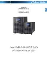
3-Stage Charger Modes (BULK/ACCEPT/FLOAT):
The 3-stage charger is applied when the battery type of OTHER is selected in the Smart Display menu.
BULK charge is a “Constant Current” charge. The maximum current is 10A. As the charge is returned to the batteries,
their voltage increases to a specic threshold (2.40VDC per cell). The charger then switches to ACCEPT mode. The
BULK charger mode generally returns the battery charge state to 80 percent of rated battery capacity.
ACCEPT charge is a “Constant Voltage” charge. This voltage, default 2.40VDC (programmable 2.20-2.45VDC) per cell, is
temperature-compensated to ensure longer battery life and proper completion of the charge cycle. This cycle is complete
when the charging current into the batteries becomes less than 0.5A or approximately six hours elapses from the time
ACCEPT mode was entered, at which time the charger switches to the FLOAT mode of operation.
FLOAT charge is a temperature-compensated charge, default 2.27VDC (programmable 2.10-2.35VDC) per cell.
During FLOAT mode, the batteries are fully charged and ready to provide backup power. The charger provides a small
maintenance charge to overcome the batteries' self-discharge characteristics and other minor DC loads within the power
supply.
Battery Voltage
Battery Current
BULK
Constant
Current Mode
(10A max) until
battery voltage
reaches the
ACCEPT level
(2.40V/cell)
ACCEPT
Constant Voltage Mode
(2.40V/cell) until battery
current demand drops
below 0.5A or time out
based on 4 minutes per
Ah battery capacity
FLOAT
Constant
Voltage Mode
(2.27V/cell)
Fig. 1-2, 3-Stage Charger Modes
1/147