
Safe Use Instructions – Emerson FloBoss 103 Flow Manager
Part D301194X012
February 2018
Remote Automation Solutions
Safe Use Instructions:
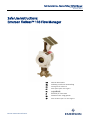
Emerson FloBoss™ 103 Flow Manager
UK
Safe Use Instructions
DE
Anleitung zur sicheren Verwendung
FR
Consignes de sécurité
PT
Instruções para uso seguro
SC
安全使用说明
IT
Istruzioni per l’uso sicuro
NL
Instructies voor veilig gebruik
SP
Instrucciones para un uso seguro

Safe Use Instructions – Emerson FloBoss 103 Flow Manager
Part D301194X012
February 2018

Safe Use Instructions – Emerson FloBoss 103 Flow Manager
Part D301194X012
February 2018
Remote Automation Solutions
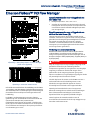
Emerson FloBoss™ 103 Flow Manager
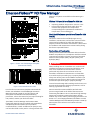
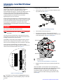
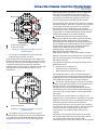
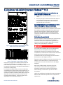
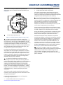
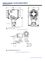
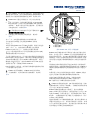
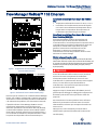
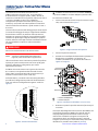
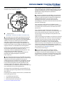
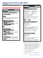
Figure 1. FloBoss 103 Flow Manager Nameplate
(ATEX Version shown)
Figure 2. Dual-Variable Sensor Label
Use this safe use instructions (SUI) document with the
FloBoss 103 and FloBoss 104 Flow Manager Instruction
Manual (part D301153X012). For full cautions and
descriptions of installation and troubleshooting
procedures, refer to this manual. If you require training for
this product, contact your local sales office.
The FloBoss 103 Flow Manager with ATEX or IECEx
flameproof approvals may be ordered with optional EIA-
232 (RS-232) communications, dial-up modem
communications, or Dual-Variable Sensor (DVS). It may
not be ordered with a solar panel or a charger board with
batteries. All options are available on the IECEx type n
version.
FloBoss 103 special conditions for Safe Use
▪ Operating Ambient Temperature: 40°C to +75°C.
▪ Ensure that the thermal fluid transfer does not
overheat the equipment to a temperature
corresponding to the spontaneous combustion
temperature of surrounding gas.
Dual-Variable Sensor special conditions for Safe
Use (X)
The device contains a thin wall diaphragm. During
installation, maintenance, and use take into account the
environmental conditions to which the diaphragm is
subjected. Follow in detail the manufacturer’s instructions
for installation and maintenance to assure safety during
the device’s expected lifetime.
Declaration of Conformity
Hereby, Remote Automation Solutions declares that the
FloBoss 103 products are in compliance with the essential
requirements and other relevant provisions of European
Directives 2004/108/EC (EMC), 94/9/EC (ATEX), and
97/23/EC (PED).
DANGER
When installing units in a hazardous area, make sure all
installation components selected are labeled for use in
such areas. Installation and maintenance must be
performed only when the area is known to be non-
hazardous. Installation or maintenance in a hazardous
area could result in personal injury or property damage.
Always turn off the power to the FloBoss 103 before you
attempt any type of wiring. Wiring powered equipment
could result in personal injury or property damage.
To avoid circuit damage when working inside the unit, use
appropriate electrostatic discharge precautions, such as
wearing a grounded wrist strap.
Do not exceed the maximum differential and static
pressure ranges listed on the label of the DVS Sensor.
Connecting the FloBoss 103 to a continuous high wattage
power source without removing the battery charger
module may result in battery overcharging and failure. See
Section 3.5.1, Overcharging Potential in the FloBoss 103 and
104 Flow Manager Instruction Manual (part D301153X012).
Do not open covers unless area is known to be non-
hazardous.

Safe Use Instructions – Emerson FloBoss 103 Flow Manager
Part D301194X012
February 2018
2 www.Emerson.com/RemoteAutomation
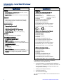
Specifications
POWER
External power charging input: 8-28 v dc, reverse
polarity protection.
Input current: 5 mA nominal. 9.5 mA at 100% duty
cycle.
Enclosure
Housing and cap: die-cast aluminum alloy with
iridite plating and paint. Stainless steel (CF8M)
version available.
ENVIRONMENTAL
Temperature (operating):
–40C to +75C.
–20C to +75C (LCD display).
Temperature (storage, non-operating):
–50C to +85C.
Relative Humidity: 5-95% non-condensing.
WEIGHT
6.58 kg (aluminum): 12.1 kg (SST).
DVS SENSOR (OPTIONAL)
DIFFERENTIAL PRESSURE INPUT
Range: 0 - 62.2 kPa.
Reference Accuracy: 0.075% or 0.10% of URL
(includes linearity, hysteresis, and repeatability effects).
STATIC PRESSURE INPUT
Range: Either Absolute or Gauge:
0 – 5516 kPa.
0 – 25,000 kPa.
Reference Accuracy: 0.075% or 0.10% of URL
(includes linearity, hysteresis, and repeatability effects).
Stability: 0.1% of upper range limit for 12 months.
Specifications
APPROVALS
ATEX Version (Flameproof & Type n)
Evaluated per Approval standards:
(Flameproof) (Type n)
EN 60079-0 (2012) EN 60079-0 (2012)
EN 60079-1 (2007) EN 60079-15 (2010)
IEC 60529 IEC 60529
Certified by LCIE as Model W40116.
ATEX Cert LCIE 03ATEX6221 X
ATEX Cert LCIE 13ATEX1033 X
Product Markings for Hazardous Locations:
Ex d IIB T5 Gb (-40°C ≤ T
amb
≤ +75°C), IP66.
Ex nA IIB T3 Gc (-40°C ≤ T
amb
≤ +75°C), IP66.
II 2/3 G. 0081
IECEx Version (Flameproof and Type n)
Evaluated per Approval standards:
IEC 60079-0 (2011)
IEC 60079-1 (2007)
IEC 60079-15 (2010)
IEC 60529
Certified by CSA as Model W40149.
IEC Cert IECEx LCI 08.0039 (Flameproof)
IEC Cert IECEx LCI 08.0015 (Type n)
Product Markings for Hazardous Locations:
Ex d IIB T5 Gb (-40°C ≤ T
amb
≤ +75°C), IP66
Ex nA IIC T3 Gc (-40°C ≤ T
amb
≤ +75°C), IP66
IECEx Version (Type n Only)
Evaluated per Approval standards:
IEC 60079-0 (2011)
IEC 60079-15 (2010)
IEC 60529
Certified by CSA as Model W40150.
IEC Cert IECEx LCI 08.0015 (Type n)
Product Markings for Hazardous Locations:
Ex nA IIC T3 Gc (-40°C ≤ T
amb
≤ +75°C), IP66
The following tools are required for installation,
maintenance, and troubleshooting:
▪ Personal computer running Microsoft
®
Windows
®
7,
Windows 8.1, or Windows 10 and Emerson Field Tools
configuration software (providing ROCLINK™ 800
configuration software).
▪ Phillips (cross-head) screwdriver.
▪ Flat-head screwdriver.
▪ Hex socket wrench (M4).
1. You receive the FloBoss 103 in a box. Remove it from
the box.

Safe Use Instructions – Emerson FloBoss 103
Part D301194X012
February 2018
www.Emerson.com/RemoteAutomation 3
2. Find a suitable location for the FloBoss 103. When
choosing an installation site, be sure to check all
clearances. Provide adequate clearance for wiring and
service. The optional LCD should be visible and accessible
for the on-site operator. See Figure 8.
3. Mounting of the FloBoss 103 can be accomplished
using one of the following methods:
▪ Pipestand mounted to a 2-inch pipestand. Use the
standard Rosemount 2" (50mm NB) pipe mounting kit
(with impulse tubing connecting the FloBoss 103 to the
meter run). Ensure that the pipestand meets all weight
requirements and installation conforms to local building
codes. See Figure 9.
Note: The Rosemount pipe mounting kit is not suitable for
the stainless steel housing. Customers must provide
an appropriate mounting.
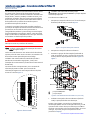
▪ Orifice Plate mounted to an orifice plate via a 3-or 5-
valve manifold. See Figure 9.
At the factory, the Dual-Variable Sensor’s connector is
mounted to a coupler, which is mounted directly on a flat
flange to the FloBoss enclosure with a 4-bolt pattern.
The optional blank plate is available when the FloBoss 103
is ordered without a DVS sensor. At the factory, the blank
plate is mounted directly on a flat flange to the FloBoss
enclosure with a 4-bolt pattern. The blank plate mounts
onto a pipestand, using the standard Rosemount 2-inch
pipe mounting kit and 2 user-supplied bolts (5/16 X 1 3/8)
and lock washers.
With either mounting method, the pressure inputs must
be piped to the process connections on the DVS sensor.
Both the static and differential pressures are piped to
female ¼-18 NPT connections on the base of the DVS
sensor. For the manifold startup/shutdown procedure,
refer to the FloBoss 103 and 104 Flow Manager Instruction
Manual (Part D301153X012).
The DVS sensor is an upstream device, meaning that the
static pressure line normally connects to the high pressure
side (labeled H on the sensor body).
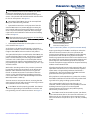
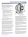
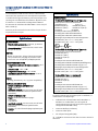
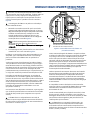
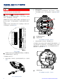
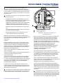
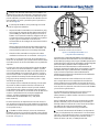
4. The FloBoss must be properly grounded. The FloBoss
103 has one grounding screw outside the enclosure and
two grounding screws inside the enclosure. See Figure 3
A
Internal Grounding Screws
B
External Grounding Screw
Figure 3. Back End of FloBoss 103 (with Termination Board)
Proper grounding of the FloBoss 103 helps to reduce the
effects of electrical noise on the unit’s operation and
protects against lightning. The FloBoss provides lightning
protection for built-in field wiring inputs and outputs.
Install a surge protection device at the service disconnect on
DC voltage source systems to protect against lightning and
power surges for the installed equipment. You may also
consider a telephone surge protector for the optional dial-up
modem communications card.
All earth grounds must have an earth to ground rod or grid
impedance of 25 ohms or less, as measured with a ground
system tester. The grounding conductor should have a
resistance of 1 ohm or less between the FloBoss enclosure
ground and the earth ground rod or grid.
If the pipeline to earth impedance is greater than 2 ohms,
the FloBoss installation should be electrically isolated and
a ground rod or grid grounding system installed.
The recommended cable for I/O signal wiring is an
insulated, shielded, twisted-pair. The twisted pair and the
shielding minimize signal errors caused by EMI
(electromagnetic interference), RFI (radio frequency
interference), and transients.
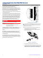
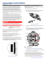
5. The FloBoss must be connected to power, I/O devices,
and communication devices. The external connections, or
field terminals, are all located on the termination board.
The terminal block accepts wires up to 1.29 mm (16 AWG)
in size.
A
B

Safe Use Instructions – Emerson FloBoss 103 Flow Manager
Part D301194X012
February 2018
4 www.Emerson.com/RemoteAutomation
The FloBoss Termination Board connectors use
compression terminals. The input power termination
(CHG+ / CHG-) uses a removable connector and
accommodates wiring up to 1.29 mm (16 AWG) in size. In
all cases, make connections by baring the end (6 mm
maximum) of the wire, inserting the bared end into the
clamp beneath the termination screw, and then
tightening the screw to 0.25 N-m.
Access to wiring connections is via field wiring entries. The
metal pipe plugs provided must remain in place on unused
entries to maintain flame-proof integrity of enclosure. If
these plugs are replaced for any reason, only install
certified plugs or thread adapters that meet or exceed the
product ratings.
DANGER
Do not over torque the connector screws.
Note: Check the input power polarity before turning on
the power.
The inserted wires should have a minimum of bare wire
exposed to prevent short circuits. Allow some slack when
making connections to prevent strain.
The FloBoss 103 accepts input voltages from 8.0 volts to
28 volts at the charge terminals (CHG+ / CHG-) with no
external current limiting (internal current limit is 200 mA).
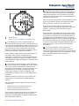
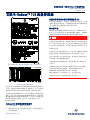
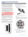
The terminals are labeled CHG+ for positive power
connection and CHG- for negative power connection on a
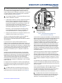
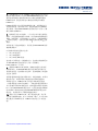
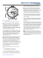
label on the termination board. See Figure 4.
Figure 4. Termination Board
6. The FloBoss 103 ships with the NORM/RESET jumper
in the NORM position, and the ON/OFF jumper in the OFF
position.
To apply power to the FloBoss 103:
▪ Unscrew the cover clamp at the base of the front end
cap (LCD end). See Figure 5.
Figure 5. Cover Clamp Assembly
▪ Unscrew the front end cap cover.
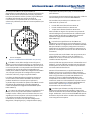
▪ Place the power jumper (located on the LCD if
installed or located at J1 on the Battery Charger Board)
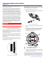
in the ON position. See Figure 6 and Figure 7.
A
NORM/RESET Jumper
B
ON/OFF Jumper
Figure 6. Front End of FloBoss 103 (with LCD)
▪ Replace the front end cap cover (LCD end) and cover
clamp.
After the FloBoss 103 completes start-up diagnostics
(RAM and other internal checks), the optional LCD displays
the date and time to indicate that the FloBoss has
completed a valid reset sequence. If the LCD does not
come on, perform trouble-shooting for possible causes
(see Step 9).
B
A

Safe Use Instructions – Emerson FloBoss 103
Part D301194X012
February 2018
www.Emerson.com/RemoteAutomation 5
A
ON/OFF Jumper
Figure 7. Front End of FloBoss 103 (without LCD)
7. The FloBoss 103 must be configured before it is
calibrated and placed into operation. Configuration must
be performed using ROCLINK 800 software, which runs on
a PC. The PC is normally connected to the LOI port of the
flow computer to transfer configuration data into the
FloBoss 103, although much of the configuration can be
done off-line and later loaded into the FloBoss.
Default values for all parameters exist in the firmware of
the FloBoss. If the default is acceptable for your
application, it can be left as it is. Perform adjustments to
the FloBoss through the configuration software. Refer to
the ROCLINK 800 Configuration Software User Manual (Part
D301159X012).
8. The calibration routines support 5-point calibration,
with the three mid-points calibrated in any order. The low-
end or zero reading is calibrated first, followed by the
high-end or full-scale reading. The three mid-points can
be calibrated next, if desired. The diagnostic analog
inputs—logic voltage (E1), battery voltage (E2), and
board/battery temperature (E5)—are not designed to be
calibrated.
With the optional I/O termination points installed, the
Analog Input can be calibrated using ROCLINK 800
software.
The built-in inputs that are supported with the 5-point
calibration are:
▪ Differential pressure located at AI Point A1.
▪ Static pressure located at AI Point A2.
▪ RTD temperature located at AI Point A3.
These inputs are assigned to the first three Analog Input
points. The calibration procedure for these inputs is
described in the ROCLINK 800 Configuration Software User
Manual (Part D301159X012).
9. To troubleshoot problems with the FloBoss 103,
identify whether the problem is with the configuration or
the hardware. Check the configuration in ROCLINK 800
software to identify any incorrect settings. Inspect the
hardware for damage. Inspect the termination boards for
connection location errors.
If you are experiencing problems with the FloBoss 103 that
appear to be software related, try resetting the FloBoss
with a warm start, a cold start, or a jumper reset.
If you are experiencing problems that appear to be
hardware-related, verify the wiring. If you still experience
problems, contact your local sales office for return
authorization.
During operation, the FloBoss 103 can be monitored (to
view or retrieve current and historical data) either locally
or remotely. Local monitoring is accomplished either by
viewing the LCD panel detailed in Section 2, or by using
ROCLINK 800 software on a PC connected through the LOI
port. Remote monitoring is performed through Comm 1
or Comm 2 of the FloBoss using ROCLINK 800 software, or
host system. Refer to Figure 4 for the communication
terminations.
10. To remove the FloBoss 103 from operation.
disconnect power from the unit and then remove all
external wiring connections. Remove the gas lines. Finally
remove the FloBoss housing from the pipestand or orifice
plate. The FloBoss may be placed in a box for
transportation.
A

Safe Use Instructions – Emerson FloBoss 103 Flow Manager
Part D301194X012
February 2018
6 www.Emerson.com/RemoteAutomation
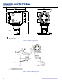
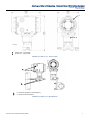
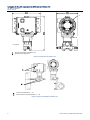
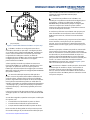
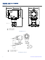
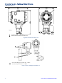
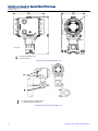
A
FloBoss 103 nameplate
B
DVS Sensor label
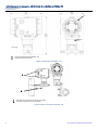
Figure 8. FloBoss 103 Dimensions
A
¾ - 14 NPT Field Wiring entries
B
¼ - 18 NPT Process connections
Figure 9. FloBoss 103 Mounting Styles
cm (inch)
A
B
A
B

Safe Use Instructions – Emerson FloBoss 103 Flow Manager
Part D301194X012
February 2018
For customer service and technical support,
visit www.Emerson.com/SupportNet.
Global Headquarters,
North America, and Latin America:
Emerson Automation Soltuions
Remote Automation Solutions
6005 Rogerdale Road
Houston, TX 77072 U.S.A.
T +1 281 879 2699 | F +1 281 988 4445
www.Emerson.com/RemoteAutomation
© 2003-2018 Remote Automation Solutions, a business unit of Emerson Automation
Solutions. All rights reserved.
This publication is for informational purposes only. While every effort has been made to ensure
accuracy, this publication shall not be read to include any warranty or guarantee, express or
implied, including as regards the products or services described or their use or applicability.
Remote Automation Solutions (RAS) reserves the right to modify or improve the designs or
specifications of its products at any time without notice. All sales are governed by RAS terms
and conditions which are available upon request. RAS accepts no responsibility for proper
selection, use or maintenance of any product, which remains solely with the purchaser and/or
end-user.
Europe:
Emerson Automation Solutions
Remote Automation Solutions
Unit 8, Waterfront Business Park
Dudley Road, Brierley Hill
Dudley UK DY5 1LX
T +44 1384 487200 | F +44 1384 487258
Middle East/Africa:
Emerson Automation Solutions
Remote Automation Solutions
Emerson FZE
P.O. Box 17033
Jebel Ali Free Zone – South 2
Dubai U.A.E.
T +971 4 8118100 | F +971 4 8865465
Asia-Pacific:
Emerson Automation Solutions
Remote Automation Solutions
1 Pandan Crescent
Singapore 128461
T +65 6777 8211| F +65 6777 0947
Remote Automation Solutions


Anleitung zur sicheren Verwendung – Emerson FloBoss 103 Durchfluss-Computer
Teile-Nr. D301194X012
Februar 2018
Remote Automation Solutions
Emerson FloBoss™ 103 Durchfluss-Computer
Abbildung 1. FloBoss 103 Durchfluss-Computer – Typenschild
(Abbildung: ATEX-Version)
Abbildung 2. Zweivariablensensor-Typenschild
Verwenden Sie diese Sicherheitsvorschriften zusammen
mit der Betriebsanleitung des FloBoss 103 und FloBoss 104
Durchfluss-Computers (Teil D301153X012). Die
vollständigen Warnhinweise und Beschreibungen von
Verfahren zur Installation sowie Störungsanalyse und -
beseitigung finden Sie in der Betriebsanleitung.
Der FloBoss 103 Durchfluss-Computer mit ATEX- oder
IECEx-Zulassung für druckfeste Kapselung kann mit
optionaler EIA-232-Kommunikation (RS-232), analoger
Modemkommunikation oder Zweivariablensensor (DVS)
bestellt werden. Die Bestellung mit einem Solarpanel oder
einer Batterieladeplatine ist nicht möglich. Alle Optionen
sind mit der Ausführung IECEx Typ n erhältlich.
Besondere Voraussetzungen für die sichere
Verwendung des FloBoss 103
▪ Betriebstemperatur: –40 °C bis +75 °C
▪ Sicherstellen, dass das Gerät durch die
Wärmeübertragung der Flüssigkeit nicht auf eine
Temperatur erhitzt wird, die der
Selbstentzündungstemperatur des vorhandenen
Gases entspricht.
Besondere Voraussetzungen für die sichere
Verwendung des Zweivariablensensors (X)
Dieses Gerät verfügt über eine dünnwandige Membran.
Bei Installation, Betrieb und Wartung sind die
Umgebungsbedingungen zu berücksichtigen, denen die
Membran ausgesetzt ist. Die Wartungs- und
Installationsanweisungen des Herstellers sind genau
einzuhalten, um die Sicherheit während der erwarteten
Gerätelebensdauer sicherzustellen.
Konformitätserklärung
Remote Automation Solutions erklärt hiermit, dass das
Produkt FloBoss 103 den grundlegenden Anforderungen
und anderen relevanten Vorschriften der EU-Richtlinien
2004/108/EG (EMV), 94/9/EG (ATEX) und 97/23/EG (PED)
entspricht.
GEFAHR
Wenn Geräte in einem explosionsgefährdeten Bereich
installiert werden, so muss darauf geachtet werden, dass
alle ausgewählten Installationskomponenten für den
Einsatz in solchen Bereichen zugelassen sind. Installations-
und Wartungsarbeiten dürfen nur dann ausgeführt
werden, wenn der Arbeitsbereich nicht in einer
explosionsgefährdeten Zone liegt. Installationsarbeiten in
einem explosionsgefährdeten Bereich können zu
Personen- und/oder zu Sachschäden führen.
Vor der Verkabelung des Gerätes stets die
Spannungsversorgung vom FloBoss trennen. Die
Verkabelung bei an die Spannungsversorgung
angeschlossenem Gerät kann zu Personen- und/oder
Sachschäden führen.
Um elektrische Schäden bei Arbeiten im Geräteinneren zu
vermeiden, müssen die erforderlichen
Vorsichtsmaßnahmen zur Vermeidung elektrostatischer
Entladungen eingehalten werden, zum Beispiel durch das
Tragen eines Antistatikbands.

Anleitung zur sicheren Verwendung – Emerson FloBoss 103 Durchfluss-Computer
Teile-Nr. D301194X012
Februar 2018
2 www.Emerson.com/RemoteAutomation
Die auf dem Typenschild des DVS-Sensors angegebenen
Höchstwerte für Differenzdruck und statischen Druck
dürfen nicht überschritten werden.
Wenn der FB103 mit einer Hochleistungs-
Spannungsquelle aufgeladen und das Akkuladegerät nach
dem Laden nicht von der Spannungsversorgung getrennt
wird, kann dies zu einer Überladung und zum Ausfall des
Akkus führen. Siehe Abschnitt 3.5.1 „Überladungspotenzial“
in der Betriebsanleitung des FloBoss 103 und FloBoss 104
Durchfluss-Computers (Teil D301153X012).
Abdeckungen nur abnehmen, wenn der Arbeitsbereich
nicht explosionsgefährdet ist.
Technische Daten
SPANNUNGSVERSORGUNG
Externer Ladestromeingang: 8–28 VDC,
Verpolungsschutz
Eingangsstrom: 5 mA nominal; 9,5 mA bei 100 %
Einschaltdauer
GEHÄUSE
Gehäuse und Deckel: Druckguss-
Aluminiumlegierung mit Iridite-Beschichtung und
Lackierung; Edelstahlausführung (CF8M) lieferbar
UMGEBUNGSBEDINGUNGEN
Betriebstemperatur: –40 bis +75 C
Digitalanzeiger: –20 bis +75 C
Lagerungstemperatur: –50 bis +85 C
Luftfeuchtigkeit im Betrieb: 5 bis 95 %, nicht
kondensierend
GEWICHT
6,58 kg (Aluminium); 12,1 kg (Edelstahl)
DVS-SENSOR (OPTIONAL)
EINGANGSDIFFERENZDRUCK
Bereich: 0–62,2 kPa
Referenzgenauigkeit: 0,075 % oder 0,10 % vom
Messende (einschl. Linearität, Hysterese und
Reproduzierbarkeit)
STATISCHER EINGANGSDRUCK
Bereich: Absolut- oder Überdruck:
0–5.516 kPa
0–25.000 kPa
Referenzgenauigkeit: 0,075 % oder 0,10 % vom
Messende (einschl. Linearität, Hysterese und
Reproduzierbarkeit)
Langzeitstabilität: 0,1 % vom Messende für
12 Monate
Technische Daten
ZULASSUNGEN
ATEX-Version (Druckfeste Kapselung und Typ n)
Bewertet nach Zulassungsnormen:
(Druckfeste Kapselung) (Typ n)
EN 60079-0 (2012) EN 60079-0 (2012)
EN 60079-1 (2007) EN 60079-15 (2010)
IEC 60529 IEC 60529
LCIE-zertifiziert als Modell W40116
ATEX Cert LCIE 03ATEX6221 X
ATEX Cert LCIE 13ATEX1033 X
Produktkennzeichnungen für explosionsgefährdete
Bereiche:
Ex d IIB T5 Gb (-40°C ≤ T
amb
≤ +75°C), IP66
Ex nA IIB T3 Gc (-40°C ≤ T
amb
≤ +75°C), IP66
II 2/3 G. 0081
IECEx-Version (Druckfeste Kapselung und Typ n)
Bewertet nach Zulassungsnormen:
IEC 60079-0 (2011)
IEC 60079-1 (2007)
IEC 60079-15 (2010)
IEC 60529
CSA-zertifiziert als Modell W40149
IEC Cert IECEx LCI 08.0039 (Druckfeste Kapselung)
IEC Cert IECEx LCI 08.0015 (Typ n)
Produktkennzeichnungen für explosionsgefährdete
Bereiche:
Ex d IIB T5 Gb (-40°C ≤ T
amb
≤ +75°C), IP66
Ex nA IIC T3 Gc (-40°C ≤ T
amb
≤ +75°C), IP66
IECEx-Version (nur Typ n)
Bewertet nach Zulassungsnormen:
IEC 60079-0 (2011)
IEC 60079-15 (2010)
IEC 60529
CSA-zertifiziert als Modell W40150
IEC Cert IECEx LCI 08.0015 (Typ n)
Produktkennzeichnungen für explosionsgefährdete
Bereiche:
Ex nA IIC T3 Gc (-40°C ≤ T
amb
≤ +75°C), IP66
Für Installation, Wartung sowie Störungsanalyse
und -beseitigung sind die folgenden Hilfsmittel bzw.
Werkzeuge erforderlich:
▪ PC mit Microsoft
®
Windows
®
7, Windows 8.1 oder
Windows 10 und der Emerson Field Tools
Konfigurationssoftware (mit der ROCLINK™ 800
Konfigurationssoftware).
▪ Kreuzschlitzschraubendreher
▪ Schlitzschraubendreher
▪ Sechskantschlüssel (M4)

Anleitung zur sicheren Verwendung – Emerson FloBoss 103 Durchfluss-Computer
Teile-Nr. D301194X012
Februar 2018
www.Emerson.com/RemoteAutomation 3
1. Der FloBoss 103 wird in einem Karton geliefert. Das
Gerät aus dem Karton herausnehmen.
2. Einen geeigneten Standort für den FloBoss
103 wählen. Bei der Auswahl eines Einbauortes alle
Abstände prüfen. Ausreichend Raum für die Kabel und für
Wartungstätigkeiten freilassen. Der optionale
Digitalanzeiger sollte für den Bediener vor Ort sichtbar
und zugänglich sein. Siehe Abbildung 8.
3. Der FloBoss 103 kann mit einer der folgenden
Methoden montiert werden:
▪ Montage an einem 50 mm-Standrohr (2 in.). Das
Standard Rosemount 50 mm (2 in.)-Standrohr-
Montagekit verwenden (wobei die Impulsleitung den
FloBoss103 mit der Messleitung verbindet).
Sicherstellen, dass das Standrohr alle
Gewichtsanforderungen erfüllt und die Installation
den örtlichen Bauvorschriften entspricht. Siehe
Abbildung 9.
Hinweis: Das Rosemount Standrohr-Montagekit ist
nicht für das Edelstahlgehäuse geeignet. Eine
geeignete Montagevorrichtung muss vom Kunden
bereitgestellt werden.
▪ Messblendenmontage über einen 3- oder 5-fach-
Ventilblock. Siehe Abbildung 8.
Der Anschluss des Zweivariablensensors wird vom
Hersteller an einem Kupplungsstück befestigt, das mit vier
Schrauben direkt auf einem flachen Flansch an das
FloBoss-Gehäuse montiert wird.
Wenn der FloBoss 103 ohne DVS-Sensor bestellt wird, ist
eine optionale Blindplatte verfügbar. Die Blindplatte wird
vom Hersteller mit vier Schrauben direkt auf einem
flachen Flansch an das FloBoss Gehäuse montiert. Die
Blindplatte kann mit dem Standard Rosemount 50 mm (2
in.)-Standrohr-Montagekit sowie zwei kundenseitig
bereitgestellten Schrauben (5/16 x 1 3/8) und
Sicherungsscheiben an einem Standrohr montiert werden.
Bei beiden Montagearten müssen die Druckeingänge mit
den Prozessanschlüssen am DVS-Sensor verrohrt werden.
Statischer Druck und Differenzdruck werden mit ¼-18
NPT-Innengewinde-Anschlüssen unten am DVS-Sensor
angeschlossen. Inbetriebnahme/Herunterfahren des
Ventilblocks siehe Betriebsanleitung des FloBoss 103 und
104 Durchfluss-Computers (Teil D301153X012).
Der DVS-Sensor ist eine in der Einlaufstrecke installierte
Vorrichtung. Dies bedeutet, dass die Leitung für den
statischen Druck in der Regel auf der Hochdruckseite
angeschlossen wird (Kennzeichnung „H“ am
Sensorgehäuse).
4. Der FloBoss muss ordnungsgemäß geerdet werden.
Der FloBoss 103 verfügt über eine Erdungsschraube außen
am Gehäuse und zwei Erdungsschrauben innen im
Gehäuse. Siehe Abbildung 3.
A
Innenliegende Erdungsschrauben
B
Außenliegende Erdungsschraube
Abbildung 3. Rückseite des FloBoss 103
(mit Anschlussplatine)
Eine gute Erdung des FloBoss 103 kann Einflüsse durch
elektrisches Rauschen auf den Gerätebetrieb minimieren
und schützt vor Überspannungen. Der FloBoss bietet
Überspannungsschutz für eingebaute
Feldverkabelungseingänge und -ausgänge. Bei Systemen
mit Gleichspannungsversorgung sollte zum Schutz der
installierten Geräte vor Blitzeinschlag und Überspannungen
ein Überspannungsschutzgerät an der
Spannungseinspeisung installiert werden. Außerdem kann
für die optionale Analogmodem-Kommunikationskarte ein
Überspannungsschutz vorgesehen werden.
Bei allen Erdungen darf die mit einem Erdungsprüfgerät
gemessene Impedanz des Erdungsstabs oder -netzes
maximal 25 Ohm betragen. Der Widerstand des Erdleiters
darf zwischen der Gehäusemasse des FloBoss und dem
Erdungsstab oder
-netz maximal 1,0 Ohm betragen.
Wenn die Impedanz zwischen Rohrleitung und Erdung
über 2 Ohm liegt, muss die FloBoss-Installation elektrisch
isoliert und ein Erdungssystem mit Erdungsstab oder -netz
installiert werden.
Für die E/A-Signale wird ein isoliertes, abgeschirmtes,
verdrilltes Doppelkabel empfohlen. Durch die Verdrillung
und die Abschirmung werden Signalfehler durch EMS
(elektromagnetische Störung), RFI (Funkstörung) und
Transienten minimiert.
5. Der FloBoss muss mit einer Spannungsversorgung,
E/A-Geräten und Kommunikationsgeräten verbunden
werden. Die externen Anschlüsse (oder Feldanschlüsse)
befinden sich alle auf der Anschlussplatine. Die
Klemmleiste ist für Adern mit einen Durchmesser bis zu
1,29 mm (AWG 16) geeignet.
A
B

Anleitung zur sicheren Verwendung – Emerson FloBoss 103 Durchfluss-Computer
Teile-Nr. D301194X012
Februar 2018
4 www.Emerson.com/RemoteAutomation
Die Anschlüsse auf der FloBoss-Anschlussplatine sind
Schraubklemmen. Für den Anschluss der
Spannungsversorgung (CHG+/CHG–) wird ein
beweglicher Stecker verwendet, der für Adern mit einem
Durchmesser bis zu 1,29 mm (AWG 16) geeignet ist. Für
den Anschluss immer das Kabelende abisolieren (maximal
6 mm), in die Klemme unter die Klemmschraube
einführen und die Schraube dann mit einem Drehmoment
von 0,25 Nm festziehen.
Die Feldverkabelung wird über Kabeleinführungen zu den
Anschlussklemmen geführt. Um die druckfeste Kapselung
des Gehäuses zu erhalten, dürfen die Metallblindstopfen
an den unbenutzten Einführungen nicht entfernt werden.
Werden diese Stopfen aus irgendeinem Grund entfernt,
dürfen sie nur durch zugelassene Kabelverschraubungen
oder Gewindeadapter ersetzt werden, die dem
Gerätestandard entsprechen oder diesen übertreffen.
GEFAHR
Die Klemmenschrauben nicht zu fest anziehen.
HINWEISE: Vor dem Einschalten der
Spannungsversorgung die Polarität des
Eingangsstroms prüfen.
Um Kurzschlüsse zu vermeiden, sollten die Adern der
eingeführten Kabel so kurz wie möglich abisoliert sein. Bei
der Herstellung von Verbindungen auf Zugentlastung
achten.
Der FloBoss 103 akzeptiert Eingangsspannungen von 8,0
bis 28 Volt an den Ladeklemmen (CHG+/CHG–) ohne
externe Strombegrenzung (die interne Strombegrenzung
beträgt 200 mA).
Die Anschlussklemmen sind auf einem Aufkleber auf der
Anschlussplatine mit CHG+ für den Plusanschluss und mit
CHG– für den Minusanschluss der Spannungsversorgung
gekennzeichnet. Siehe Abbildung 4.
Abbildung 4. Anschlussplatine
6. Die Steckbrücke NORM/RESET des FloBoss 103 ist bei
Auslieferung in der Position NORM und die Steckbrücke
ON/OFF in der Position OFF.
Aktivieren der Spannungsversorgung des FloBoss 103:
▪ Die Deckelklemme unten am vorderen
Gehäusedeckel (auf der Seite des Digitalanzeigers)
lösen. Siehe Abbildung 4.
Abbildung 5. Deckelklemme
▪ Den vorderen Gehäusedeckel abschrauben.
▪ Die Steckbrücke für die Spannungsversorgung (auf dem
Digitalanzeiger oder J1 auf der Batterieladeplatine) in die
Position ON setzen. Siehe Abbildung 6 und Abbildung 7.

Anleitung zur sicheren Verwendung – Emerson FloBoss 103 Durchfluss-Computer
Teile-Nr. D301194X012
Februar 2018
www.Emerson.com/RemoteAutomation 5
A
Steckbrücke NORM/RESET
B
Steckbrücke ON/OFF
Abbildung 6. Vorderseite des FloBoss 103 (mit
Digitalanzeiger)
▪ Den vorderen Gehäusedeckel (auf der Seite des
Digitalanzeigers) wieder einsetzen.
Nach Abschluss der Einschaltdiagnose des FloBoss 103
(RAM und andere interne Prüfungen) erscheinen Datum
und Uhrzeit auf dem optionalen Digitalanzeiger, um die
erfolgreiche Initialisierung anzuzeigen. Wenn der
Digitalanzeiger nichts anzeigt, für mögliche Ursachen die
Störungsanalyse und -beseitigung (siehe Schritt 9)
durchführen.
A
Steckbrücke ON/OFF
Abbildung 7. Vorderseite des FloBoss 103 (ohne
Digitalanzeiger)
7. Der FloBoss 103 muss vor der Kalibrierung und
Inbetriebnahme konfiguriert werden. Die Konfiguration
muss mit dem Programm ROCLINK 800 auf einem PC
ausgeführt werden. Der PC wird zur Übertragung der
Konfigurationsdaten zum FloBoss 103 in der Regel mit
dem Anschluss am Bedieninterface des Durchfluss-
Computers verbunden. Ein Großteil der Konfiguration
kann jedoch auch offline durchgeführt und zu einem
späteren Zeitpunkt in den FloBoss geladen werden.
Die Standardwerte für alle Parameter sind in der Firmware
des FloBoss definiert. Wenn die Vorgaben für die jeweilige
Anwendung akzeptabel sind, können sie unverändert
übernommen werden. Änderungen an den FloBoss-
Einstellungen werden mit dem Konfigurationsprogramm
vorgenommen. Siehe Betriebsanleitung des ROCLINK 800
Konfigurationsprogramms (Teil D301159X012).
8. Die Kalibrierungsroutinen unterstützen 5-Punkt-
Kalibrierung, wobei die drei mittleren Punkte in beliebiger
Reihenfolge kalibriert werden können. Zuerst wird der
Messanfang bzw. der Nullpunkt und danach das Messende
bzw. der Messbereichsendwert kalibriert. Die drei mittleren
Punkte können, falls erforderlich, als Nächstes kalibriert
werden. Die für Diagnosezwecke vorgesehenen
Analogeingänge – logische Spannung (E1),
Batteriespannung (E2) und Platinen-/
Batterietemperatur (E5) – müssen nicht kalibriert werden.
Wenn die optionalen E/A-Anschlusspunkte installiert sind,
kann der Analogeingang mit dem Programm ROCLINK
800 kalibriert werden.
Die folgenden eingebauten Eingänge unterstützen die 5-
Punkt-Kalibrierung:
▪ Differenzdruck an AI Punkt A1
▪ Statischer Druck an AI Punkt A2
▪ Widerstandsthermometer an AI Punkt A3
Diese Eingänge sind den ersten drei Analogeingängen
zugeordnet. Eine Beschreibung der Kalibrierung für diese
Eingänge finden Sie in der Betriebsanleitung des ROCLINK
800 Konfigurationsprogramms (Teil D301159X012).
9. Zur Analyse und Beseitigung von Problemen mit dem
FloBoss 103 zunächst bestimmen, ob das Problem an der
Konfiguration oder an der Hardware liegt. Die
Konfiguration im Programm ROCLINK 800 auf falsche
Einstellungen prüfen. Die Hardware auf Beschädigungen
untersuchen. Die Anschlussplatinen auf Anschlussfehler
überprüfen.
Wenn Probleme mit dem FloBoss 103 auftreten, die
möglicherweise auf die Software zurückzuführen sind, den
FloBoss mit einem Warmstart, einem Kaltstart oder einer
Initialisierung mit der Steckbrücke zurücksetzen.
Falls Probleme auftreten, deren Ursache in der Hardware
vermutet wird, die Verkabelung prüfen. Falls die Probleme
weiterhin bestehen, wenden Sie sich an Ihr lokales
Vertriebsbüro, um eine Rückgabegenehmigung zu
erhalten.
Der FloBoss 103 kann während des Betriebs lokal oder
extern überwacht werden (zum Anzeigen oder Abrufen
von aktuellen oder historischen Daten). Lokale
Überwachung ist entweder durch Ablesen des in Abschnitt
B
A
A

Anleitung zur sicheren Verwendung – Emerson FloBoss 103 Durchfluss-Computer
Teile-Nr. D301194X012
Februar 2018
6 www.Emerson.com/RemoteAutomation
2 beschriebenen Digitalanzeigers oder mit dem
Programm ROCLINK 800 auf einem über den Anschluss
am Bedieninterface verbundenen PC möglich. Externe
Überwachung kann über Comm 1 oder Comm 2 des
FloBoss mit dem Programm ROCLINK 800 oder einem
Hostsystem durchgeführt werden. Kommunikationsanschlüsse
siehe Abbildung 4.
10. Um den FloBoss 103 außer Betrieb zu setzen, die
Spannungsversorgung vom Gerät trennen und dann alle
externen Kabelverbindungen entfernen. Die Gasleitungen
entfernen. Zum Schluss das FloBoss-Gehäuse vom
Standrohr oder der Messblende abnehmen. Der FloBoss
kann für den Transport in einen Karton gelegt werden.

Anleitung zur sicheren Verwendung – Emerson FloBoss 103 Durchfluss-Computer
Teile-Nr. D301194X012
Februar 2018
www.Emerson.com/RemoteAutomation 7
A
FloBoss 103 – Typenschild
B
DVS Sensor – Typenschild
Abbildung 8. FloBoss 103 – Abmessungen
A
¾ - 14 NPT-Eingänge für Feldverkabelung
B
¼ - 18 NPT-Prozessanschlüsse
Abbildung 9. FloBoss 103 - Montagearten
mm (in.)
A
B
A
B

Anleitung zur sicheren Verwendung – Emerson FloBoss 103 Durchfluss-Computer
Teile-Nr. D301194X012
Februar 2018
Kundendienst und technische Unterstützung
finden Sie unter www.Emerson.com/SupportNet.
Weltweite Firmenzentrale
Nordamerika/Lateinamerika:
Emerson Automation Solutions
Remote Automation Solutions
6005 Rogerdale Road
Houston, TX 77072, USA
Tel.: +1 281 879 2699 | Fax: +1 281 988 4445
www.Emerson.com/RemoteAutomation
© 2003 - 2018 Remote Automation Solutions, eine Geschäftseinheit von Emerson
Automation Solutions. Alle Rechte vorbehalten.
Diese Publikation dient nur zu Informationszwecken. Obwohl große Sorgfalt zur
Gewährleistung ihrer Exaktheit aufgewendet wurde, kann diese Publikation nicht zur Ableitung
von Garantie- oder Gewährleistungsansprüchen, ob ausdrücklicher Art oder stillschweigend,
hinsichtlich der in dieser Publikation beschriebenen Produkte oder Dienstleistungen oder ihres
Gebrauchs oder ihrer Verwendbarkeit herangezogen werden. Remote Automation Solutions
(RAS) behält sich das Recht vor, jederzeit und ohne Vorankündigung die Konstruktion und
technischen Daten seiner Produkte zu ändern oder zu verbessern. Für alle Verkäufe gelten
unsere (RAS) allgemeinen Geschäftsbedingungen, die auf Anfrage zur Verfügung gestellt
werden. Die Verantwortung bezüglich der richtigen Auswahl, Verwendung oder Wartung von
jeglichen Produkten liegt allein beim Käufer und Endanwender.
Europa:
Emerson Automation Solutions
Remote Automation Solutions
Unit 8, Waterfront Business Park
Dudley Road, Brierley Hill
Dudley UK DY5 1LX
Tel.: +44 1384 487200 | Fax: +44 1384 487258
Naher Osten/Afrika:
Emerson Automation Solutions
Remote Automation Solutions
Emerson FZE
P.O. Box 17033
Jebel Ali Free Zone – South 2
Dubai, Vereinigte Arabische Emirate
Tel.: +971 4 8118100 | Fax: +971 4 8865465
Asien/Pazifik:
Emerson Automation Solutions
Remote Automation Solutions
1 Pandan Crescent
Singapur 128461
Tel.: +65 6777 8211| Fax: +65 6777 0947
Remote Automation Solutions

Consignes de sécurité – Calculateur de débit Emerson FloBoss 103
réf. D301194X012
Février 2018
Remote Automation Solutions
Calculateur de débit Emerson FloBoss
TM
103
Figure 1. Plaque signalétique du calculateur de débit
FloBoss 103 (version ATEX illustrée)
Figure 2. Étiquette du capteur à deux variables
Utilisez ces consignes avec le Manuel d’instructions du
calculateur de débit FloBoss 103 et FloBoss 104 (réf.
D301153X012). Consultez ce manuel pour obtenir toutes
les mesures de précaution, descriptions d’installation et
procédures de dépannage.
Le calculateur de débit FloBoss 103 avec certification
d’antidéflagrance ATEX ou IECEx est disponible avec les
options de communication EIA-232 (RS-232), modem
commuté ou capteur à deux variables (DVS). Il n’est pas
disponible avec un panneau solaire ou une carte de
chargement avec batteries. Toutes les options sont
disponibles sur la version IECEx Type « n ».
Conditions spéciales pour une utilisation en
toute sécurité du FloBoss 103
▪ Température ambiante de fonctionnement : -40 °C à
+75 °C.
▪ Assurez-vous que le transfert de fluide thermique ne
surchauffe pas l’équipement à une température
correspondant à la température de combustion
spontanée du gaz environnant.
Conditions spéciales pour l’utilisation en toute
sécurité du capteur à deux variables (X)
Cet appareil contient une membrane fine. Durant
l’installation, la maintenance et l’utilisation, tenez compte
des conditions ambiantes auxquelles la membrane est
exposée. Afin de garantir la sécurité tout au long de la
durée de vie de l’appareil, suivez minutieusement les
instructions du fabricant concernant l’installation et la
maintenance.
Déclaration de conformité
Remote Automation Solutions déclare par la présente que
le produit FloBoss 103 est conforme aux exigences
essentielles et aux autres dispositions applicables des
Directives européennes 2004/108/EC (EMC), 94/9/EC
(ATEX) et 97/23/EC (PED), le cas échéant.
DANGER
Si les unités sont installées dans une zone dangereuse,
assurez-vous que les étiquettes des composants
sélectionnés autorisent leur usage dans une telle zone.
L’installation et la maintenance ne doivent être effectuées
que lorsque la zone ne présente aucun risque.
L’installation dans une zone dangereuse peut entraîner
des blessures ou des dégâts matériels.
Éteignez toujours le FloBoss avant toute intervention sur le
câblage. Toute intervention sur un équipement sous
tension pourrait entraîner des blessures ou des dégâts
matériels.
Pour éviter d’endommager les circuits lors d’une
intervention à l’intérieur de l’unité, appliquez les
précautions pertinentes concernant les décharges
électrostatiques, notamment le port d’un bracelet
antistatique.
Veillez à ne pas dépasser les plages de pression statique et
différentielle maximales répertoriées sur l’étiquette du
capteur DVS.

Consignes de sécurité – Calculateur de débit Emerson FloBoss 103
réf. D301194X012
Février 2018
2 www.Emerson.com/RemoteAutomation
Le raccordement du FB103 à une source d’alimentation
continue à forte puissance sans avoir déposé au préalable
le module du chargeur de batterie pourrait provoquer une
surcharge et une défaillance de la batterie. Reportez-vous
à la Section 3.5.1 Potentiel de surcharge dans le Manuel
d’instructions du calculateur de débit FloBoss 103 et 104 (réf.
D301153X012).
N’ouvrez pas les couvercles à moins d’être sûr que la zone
ne présente aucun risque.
Spécifications
ALIMENTATION
Prise de recharge externe : 8 à 28 Vcc, protection
contre l’inversement de polarité
Courant d’entrée : 5 mA nominal. 9,5 mA à 100 %
du cycle de service
BOÎTIER
Boîtier et capuchon : alliage d’aluminium moulé
sous pression avec plaquage et peinture iridiés.
Version en acier inoxydable (CF8M) disponible.
CONDITIONS AMBIANTES
Température ambiante de fonctionnement : -40 à
+75 C
Indicateur LCD : -20 à +75 C
Température de stockage : -50 à +85 C
Humidité relative de fonctionnement : 5 à 95 %,
sans condensation
POIDS
6,58 kg (aluminium) ; 12,1 kg (acier inoxydable)
CAPTEUR DVS (EN OPTION)
ENTRÉE DE PRESSION DIFFÉRENTIELLE
Plage : 0 à 62,2 kPa
Incertitude nominale : 0,075 % ou 0,10 % de la PLS
(sont inclus les effets de linéarité, d’hystérésis et de
répétabilité)
ENTRÉE DE PRESSION FIXE
Plage : Coordonnées absolues ou jauge :
0-5 516 kPa
0-25 000 kPa
Incertitude nominale : 0,075 % ou 0,10 % de la PLS
(inclut les effets de linéarité, d’hystérésis et de
répétabilité)
Stabilité : 0,1 % de la limite de plage supérieure pour
12 mois
Spécifications
CERTIFICATIONS :
Version ATEX (Antidéflagrance et Type « n »)
Évalué selon les normes de certification :
(Antidéflagrance) (Type « n »)
EN 60079-0 (2012) EN 60079-0 (2012)
EN 60079-1 (2007) EN 60079-15 (2010)
CEI 60529 CEI 60529
Certifié par LCIE en tant que W40116.
Homologation ATEX LCIE 03ATEX6221 X
Homologation ATEX LCIE 13ATEX1033 X
Marquages du produit pour les zones dangereuses :
Ex d IIB T5 Gb (-40°C ≤ T
amb
≤ +75°C), IP66.
Ex nA IIB T3 Gc (-40°C ≤ T
amb
≤ +75°C), IP66.
II 2/3 G. 0081
Version IECEx (Antidéflagrance et Type « n »)
Évalué selon les normes de certification :
CEI 60079-0 (2011)
CEI 60079-1 (2007)
CEI 60079-15 (2010)
CEI 60529
Certifié par CSA comme modèle W40149.
Homologation CEI IECEx LCI 08.0039 (Antidéflagrance)
Homologation CEI IECEx LCI 08.0015 (Type « n »)
Marquages du produit pour les zones dangereuses :
Ex d IIB T5 Gb (-40°C ≤ T
amb
≤ +75°C), IP66
Ex nA IIC T3 Gc (-40°C ≤ T
amb
≤ +75°C), IP66
Version IECEx (Type « n » seulement)
Évalué selon les normes de certification :
CEI 60079-0 (2011)
CEI 60079-15 (2010)
CEI 60529
Certifié par CSA comme modèle W40150.
Homologation CEI IECEx LCI 08.0015 (Type « n »)
Marquages du produit pour les zones dangereuses :
Ex nA IIC T3 Gc (-40°C ≤ T
amb
≤ +75°C), IP66
Les outils suivants sont nécessaires pour l’installation, la
maintenance et le dépannage :
▪ Ordinateur PC exécutant Microsoft
®
Windows
®
7,
Windows 8.1 ou Windows 10 et le logiciel de
configuration Emerson Field Tools (avec logiciel de
configuration ROCLINK™ 800).
▪ Tournevis Phillips (cruciforme)
▪ Tournevis à tête plate
▪ Clé à cliquet hexagonale (M4)
1. Le FloBoss 103 vous est livré dans un carton. Sortez-le
du carton.
A página está carregando...
A página está carregando...
A página está carregando...
A página está carregando...
A página está carregando...
A página está carregando...
A página está carregando...
A página está carregando...
A página está carregando...
A página está carregando...
A página está carregando...
A página está carregando...
A página está carregando...
A página está carregando...
A página está carregando...
A página está carregando...
A página está carregando...
A página está carregando...
A página está carregando...
A página está carregando...
A página está carregando...
A página está carregando...
A página está carregando...
A página está carregando...
A página está carregando...
A página está carregando...
A página está carregando...
A página está carregando...
A página está carregando...
A página está carregando...
A página está carregando...
A página está carregando...
A página está carregando...
A página está carregando...
A página está carregando...
A página está carregando...
A página está carregando...
A página está carregando...
A página está carregando...
A página está carregando...
A página está carregando...
A página está carregando...
A página está carregando...
A página está carregando...
A página está carregando...
A página está carregando...
-
 1
1
-
 2
2
-
 3
3
-
 4
4
-
 5
5
-
 6
6
-
 7
7
-
 8
8
-
 9
9
-
 10
10
-
 11
11
-
 12
12
-
 13
13
-
 14
14
-
 15
15
-
 16
16
-
 17
17
-
 18
18
-
 19
19
-
 20
20
-
 21
21
-
 22
22
-
 23
23
-
 24
24
-
 25
25
-
 26
26
-
 27
27
-
 28
28
-
 29
29
-
 30
30
-
 31
31
-
 32
32
-
 33
33
-
 34
34
-
 35
35
-
 36
36
-
 37
37
-
 38
38
-
 39
39
-
 40
40
-
 41
41
-
 42
42
-
 43
43
-
 44
44
-
 45
45
-
 46
46
-
 47
47
-
 48
48
-
 49
49
-
 50
50
-
 51
51
-
 52
52
-
 53
53
-
 54
54
-
 55
55
-
 56
56
-
 57
57
-
 58
58
-
 59
59
-
 60
60
-
 61
61
-
 62
62
-
 63
63
-
 64
64
-
 65
65
-
 66
66


Remote Automation Solutions FloBoss 103 Flow Manager Instruções de operação
- Tipo
- Instruções de operação
- Este manual também é adequado para
em outras línguas
- español: Remote Automation Solutions FloBoss 103 Flow Manager Instrucciones de operación
- français: Remote Automation Solutions FloBoss 103 Flow Manager Mode d'emploi
- italiano: Remote Automation Solutions FloBoss 103 Flow Manager Istruzioni per l'uso
- English: Remote Automation Solutions FloBoss 103 Flow Manager Operating instructions
- Nederlands: Remote Automation Solutions FloBoss 103 Flow Manager Handleiding
- Deutsch: Remote Automation Solutions FloBoss 103 Flow Manager Bedienungsanleitung
Artigos relacionados
-
 Remote Automation Solutions FloBoss 104 Flow Manager Instruções de operação
-
 Remote Automation Solutions FloBoss 104 Flow Manager Instruções de operação
-
 Remote Automation Solutions MVS205 Multi-Variable Sensor Instruções de operação
-
 Remote Automation Solutions FloBoss 103 Flow Manager in Manual do proprietário
-
 Remote Automation Solutions FloBoss 407 Flow Manager in Manual do proprietário
-
 Remote Automation Solutions RL101 ROCLINK (Software de Guia de usuario
-
 Remote Automation Solutions DL8000 Preset Controller Instruções de operação
-
 Remote Automation Solutions ROC800-Series Remote Instruções de operação
-
Remote Automation Solutions FloBoss 107 Flow Manager Manual do proprietário
-
 Remote Automation Solutions Foundation Fieldbus Interface Instruções de operação


Outros documentos
-
Emerson FB1100 Instruções de operação
-
Emerson D301801X012 Instruções de operação
-
Rosemount 8732 Sistema medidor de vazão eletromagnético de montagem integral ou remota com FOUNDATION™ fieldbus Manual do proprietário
-
-
ABB TSHD Installation Instructions Manual