Emerson D301801X012 Instruções de operação

Tipo
Instruções de operação
Safe Use Instructions Emerson FB2200
Part D301801X012
June 2021
Remote Automation Solutions
Safe Use Instructions:
Emerson FB2200 Flow Computer
UK
Safe Use Instructions
DE
Anleitung zur sicheren Verwendung
FR
Consignes de sécurité
PT
Instruções para uso seguro
SC
安全使用说明
IT
Istruzioni per l’uso sicuro
NL
Instructies voor veilig gebruik
SP
Instrucciones para un uso seguro
Safe Use Instructions Emerson FB2200
Part D301801X012
June 2021
Safe Use Instructions Emerson FB2200
Part D301801X012
June 2021
Remote Automation Solutions
Emerson FB2200 Flow Computer
Figure 1. Emerson FB2200 Label
(Non-sparking with Integral Sensor)
Use this safe use instructions (SUI) document with the
Emerson FB2200 Flow Computer Instruction Manual (part
D301784X012). For full cautions and descriptions of
installation and troubleshooting procedures, refer to this
manual. If you require training for this product, contact
your local sales office.
The Emerson FB2200 Flow Computer (or “FB2200”) with
ATEX approval may be ordered with any of the optional
communications or I/O modules listed in the product data
sheet Emerson FB2200 Flow Computer (part
D301792X012).
Figure 2. Emerson FB2200 Label
(Non-sparking without Integral Sensor)
Statement of Conformity
Hereby, Remote Automation Solutions declares that the
Emerson FB2200 Flow Computers are in compliance with
the essential requirements and other relevant provisions
of European Directives 2014/30/EU (EMC), and
2014/34/EU (ATEX).
Specific Conditions of Use
Use equipment in an area of not more than pollution
degree 2.
Make provisions to ensure, in the event of transient
disturbances, that the rated voltage does not exceed
140% of the peak rated voltage.
Lead acid battery and solar power options are not for
use in ATEX applications.
Impact tests on the display were conducted based on
Group II values for the low risk of mechanical danger,
in accordance with Table 13 of both EN 60079-
0:2012+A11:2013 and IEC 600790 6th Edition. Install
flow computers with displays in areas where the risk of
impact is low.
In Zone 2 installations, ensure that the flow computer
is installed and used to prevent the danger of
electrostatic charges.
The FB2200 enclosure requires a tool to open. Refer to
the Physical Security section in Chapter 1 of the
Emerson FB2200 Flow Computer Instruction Manual
(part D301784X012) for further details.
Refer to Table 1 for replacement parts.
Table 1. Replacement Parts
Replacement Part
Kit Number
Field Replacement
Guide document
number
8-Channel Expansion
I/O Board
400217010-KIT D301804X012
6-Channel Expansion
I/O Board
400215010-KIT D301803X012
HMI Module Display
Assembly
399379-01-0,
621627011-KIT,
399380-01-0,
621627020-KIT
D301822X012
I/O Termination
Board
400210010-KIT,
358807010-KIT D301805X012
CPU Enclosure and
Electronics
621673-01-0,
621674-01-0,
621675-01-0,
621676-01-0,
621678-01-0,
400209010-KIT,
399260-01-0,
399264-01-0,
400211010-KIT
D301803X012
Sensor Variable Kit Number D301843X012
Door Accessories
399291-01-0,
399267-01-0,
399266-01-0,
621661010-KIT,
399394-00-0
D301825X012
Relay
395828-01-0
D301847X012
Coin Cell Battery
395620-03-1
D301855X012
Safe Use Instructions Emerson FB2200
Part D301801X012
June 2021
2 www.Emerson.com/RemoteAutomation
Specifications
POWER
Operating Range:
10.5 Vdc to 30 Vdc (10W max power)
ENCLOSURE
Housing:
Powder-coat aluminum, with lockable door
Compression-molded fiberglass, with lockable door
ENVIRONMENTAL
Operating Temperature:
Non-sparking (Ex nA): 25°C to +55°C.
Storage Temp.:
40°C to +85°C.
Operating Humidity:
5-95% non-condensing per IEC
60068-2-3.
WEIGHT
6.94 kg (15.3 lbs) (fiberglass enclosure)
10.75 kg (23.7 lbs) (aluminum enclosure)
APPROVALS
Evaluated to the following European Standards (EMC):
EN 61326-1:2013 (Emissions)
EN 61326-2-3:2013 (Immunity)
Immunity
EN 61000-4-2 (Electro Static Discharge)
EN 61000-4-3 (Radiated Immunity)
EN 61000-4-4 (Fast Transients)
EN 61000-4-5 (Surges)
EN 61000-4-6 (Conducted RF)
EN 61000-4-8 (Power Frequency Magnetic Field)
EN 61000-4-17 (Voltage Ripple)
EN 61000-4-29 (Voltage Dips and Interrupts)
Evaluated to the following Approval Standards:
Directive 2014/34/EU
EN 60079-0:2012+A11:2013
EN 60079-15:2010
Evaluated to the following Standards (IEC):
IEC 60079-0 (2011), 6th Edition
IEC 60079-15 (2010), 4th Edition
Product Markings for Hazardous Locations:
Ex nA IIC T4 Gc (–25°C Tamb +55°C),
II 3 G
Cert. No. DEMKO 16 ATEX 1579X
DANGER
When installing units in a hazardous area, make sure all
installation components selected are labeled for use in
such areas. Installation and maintenance must be
performed only when the area is known to be non-
hazardous. Installation or maintenance in a hazardous
area could result in personal injury or property damage.
Always turn off the power to the FB2200 before you
attempt any type of wiring. Wiring of powered
equipment could result in personal injury or property
damage.
To avoid circuit damage when working
inside the unit, use appropriate electrostatic discharge
precautions, such as wearing a grounded wrist strap.
Check the input power polarity before connecting power
to the FB2200. Wiring of powered equipment could result
in personal injury or property damage.
The following tools are required for installation,
maintenance, and troubleshooting:
Personal computer running Microsoft® Windows® 7
Professional or Windows 8.1 Pro, or Windows 10 Pro
and Emerson Field Tools configuration software
(providing FBxConnect™).
#1 and #2 Phillips (cross-head) screwdriver.
3 mm (1/8-inch) flat-head screwdriver.
Unpacking
You receive the FB2200 in a box. Remove it from the box.
Examine the packing list carefully to ensure you have all
components.
Installation
1. Find a suitable location for the FB2200. When
selecting an installation site, be sure to check all
clearances. The FB2200 housing is designed to
withstand a variety of inclement conditions. The
optional LCD should be visible and accessible for the
on-site operator.
Safe Use Instructions Emerson FB2200
Part D301801X012
June 2021
www.Emerson.com/RemoteAutomation 3
Figure 3. Front View of the FB2200 (Aluminum Enclosure)
(with optional integral MVS sensor)
Figure 4. Side View of the FB2200 (Aluminum Enclosure)
(with optional integral MVS sensor)
Figure 5. Front View of the FB2200 (Fiberglass Enclosure)
(with optional integral MVS sensor)
Figure 6. Side View of the FB2200 (Fiberglass Enclosure)
(with optional integral MVS sensor)
Safe Use Instructions Emerson FB2200
Part D301801X012
June 2021
4 www.Emerson.com/RemoteAutomation
2. The FB2200 mounts on a two-inch pipe or pole (see
Figure 7) or can be wall- or panel-mounted using the
four holes in the case and suitable attachments.
Figure 7. FB2200 (Aluminum Enclosure) on Pipe Mount
Grounding
Open the front door of the FB2200 as detailed in either
Chapter 2 of the Emerson FB2200 Flow Computer
Instruction Manual (part D301784X012) or in the
Emerson FB2200 Flow Computer Quick Start Guide (part
D301788X012).
If your company has no specific grounding
requirements, install the FB2200 as a “floating”
(unconnected to ground) system using the ground lug
and routing the ground wire through one of the conduit
fittings. Otherwise, follow your company’s specific
grounding practices. However, if you are making a
connection between a grounded device and an EIA-232
(RS-232) port, ground the FB2200’s power supply.
If you must ground the equipment, observe the
following guidelines:
When the equipment uses a DC voltage source,
the grounding system must terminate at the
service disconnect. All equipment grounding
conductorsincluding wire or conduit carrying the
power supply conductorsmust provide an
uninterrupted electrical path to the service
disconnect.
Improper grounding or poor grounding practices
can often cause problems, such as introducing
ground loops into the system. Properly grounding
the FB2200 helps to reduce the effects of electrical
noise on the unit’s operation and protects against
lightning. Install a surge protection device at the
service disconnect on DC voltage source systems
to protect the installed equipment against
lightning and power surges.
Ensure that the flow computer’s ground is
separate from the cathodic protection ground.
The grounding installation method for the FB2200
depends on whether the pipeline has cathodic
protection. On pipelines with cathodic protection,
electrically isolate the FB2200 from the pipeline. All
earth grounds must have an earth-to-ground rod or
grid impedance of 25 ohms or less, as measured with
a ground system tester.
Wiring to Power
Wire the FB2200 through the conduit fittings on the
bottom of the housing. The terminal blocks accept wiring
2mm in diameter/3mm2 or smaller. To connect the wire to
the removable block compression terminals:
Bare the end (6mm maximum) of the wire.
Insert the bared end of the wire into the clamp
beneath the termination screw.
Tighten the screw.
Expose a minimum of bare wire to prevent short circuits.
Allow some slack when making connections to prevent
strain.
Connect the power wiring. Review the power wiring
descriptions in Chapter 2 of the Emerson FB2200 Flow
Computer Instruction Manual (part D301784X012).
Verify the hook-up polarity is correct.
To make DC power supply connections:
Remove the terminal block connector from the
socket.
Insert each bare wire end into its appropriate
connector and secure the wire (see Figures 7 and 8).
Plug the terminal block connector back into the
socket.
Figure 8. Wiring to DC Power Supply
Refer to the Emerson FB2200 Flow Computer Quick Start
Guide (part D301788X012) for detailed instructions on
connecting the battery.
Wiring to Communications & I/O
Connect the wiring to the terminal blocks on the I/O and
communications modules. Refer to either Section 2.8 in
Chapter 2 of the Emerson FB2200 Flow Computer
Safe Use Instructions Emerson FB2200
Part D301801X012
June 2021
www.Emerson.com/RemoteAutomation 5
Instruction Manual (part D301784X012) or the Emerson
FB2200 Flow Computer Quick Start Guide (part
D301788X012) for wiring schematics and
explanations.
Once you have wired the communications and I/O,
close and secure the cover of FB2200.
Powering Up the FB2200
DANGER
Do not attempt to connect power or disconnect power
from the unit in a hazardous area. Ensure the area is
non-hazardous. Failure to do so could result in an
explosion.
1. To start up the FB2200, apply power.
When you turn power on, the backlight on the HMI
module lights for about 5 seconds, then turns off.
During this time the database begins to initialize.
After about 45 seconds the backlight on the HMI
turns on again and starts to display live data.
Periodically inspect the wiring for signs of
deterioration.
Configuring the FB2200
You must install Emerson’s Field Tools configuration
software (which includes FBxConnect™) on your PC to
configure the FB2200 for use. Refer to the Emerson
FB2200 Flow Computer Quick Start Guide (part
D301788X012) for instructions on installing and using
this software.
Resetting the FB2200
If you are experiencing problems that appear to be
software related, try resetting the FB2200. Refer to the
Service and Troubleshooting chapter in the Emerson
FB2200 Flow Computer Instruction Manual (part
D301784X012) for specific instructions.
Note: You lose all configuration and log data with a
reset. If possible, make a backup of
configuration and log data before attempting
any type of reset.
Replacing Parts in the FB2200
Refer to Table 1 for a list of user-serviceable parts and their
respective Field Replacement Guides.
Returning the FB2200
If you are experiencing problems that appear to be
hardware-related, verify the wiring. If you still experience
problems, contact your local sales office for return
authorization. To return the device:
1. Back up all configuration and data before removing
the device from process. Then remove power from
the device and remove all external wiring.
2. Uninstall the device.
3. Place the device into a box safe for shipping or
storage.
Safe Use Instructions Emerson FB2200
Part D301801X012
June 2021
For customer service and technical support,
visit www.Emerson.com/SupportNet.
Global Headquarters,
North America, and Latin America:
Emerson Automation Solutions
Remote Automation Solutions
6005 Rogerdale Road
Houston, TX 77072 U.S.A.
T +1 281 879 2699 | F +1 281 988 4445
www.Emerson.com/RemoteAutomation
© 2017-2021 Remote Automation Solutions, a business unit of Emerson Automation
Solutions. All rights reserved.
This publication is for informational purposes only. While every effort has been made to ensure
accuracy, this publication shall not be read to include any warranty or guarantee, express or
implied, including as regards the products or services described or their use or applicability.
Remote Automation Solutions (RAS) reserves the right to modify or improve the designs or
specifications of its products at any time without notice. All sales are governed by RAS terms
and conditions which are available upon request. RAS accepts no responsibility for proper
selection, use or maintenance of any product, which remains solely with the purchaser and/or
end-user.
Europe:
Emerson Automation Solutions
Remote Automation Solutions
Unit 1, Waterfront Business Park
Dudley Road, Brierley Hill
Dudley DY5 1LX UK
T +44 1384 487200
Middle East/Africa:
Emerson Automation Solutions
Remote Automation Solutions
Emerson FZE
P.O. Box 17033
Jebel Ali Free Zone South 2
Dubai U.A.E.
T +971 4 8118100 | F +971 4 8865465
Asia-Pacific:
Emerson Automation Solutions
Remote Automation Solutions
1 Pandan Crescent
Singapore 128461
T +65 6777 8211| F +65 6777 0947
Remote Automation Solutions
Anleitung zur sicheren Verwendung Emerson FB2200
Dok.-Nr. D301801X012
Juni 2021
Remote Automation Solutions
Emerson FB2200 Flow Computer
Abbildung 1. Emerson FB2200 Typenschild
(funkenfrei mit integriertem Sensor)
Diese Anleitung zur sicheren Verwendung ergänzt die
Betriebsanleitung für den Emerson FB2200 Flow Computer
(Dok.-Nr. D301784X012). In diesem Handbuch finden Sie
ausführliche Warnungen, eine Installationsanleitung und
Verfahren zur Problemlösung. Sollten Sie für dieses
Produkt eine Schulung benötigen, wenden Sie sich bitte
an Ihr örtliches Vertriebsbüro.
Der Emerson FB2200 Flow Computer (oder „FB2200“) mit
ATEX-Zulassung kann mit einem der optionalen
Kommunikations- oder E/A-Module bestellt werden, die
auf dem Produktdatenblatt des Emerson FB2200 Flow
Computers (Dok.-Nr. D301792X012) aufgeführt sind.
Abbildung 2. Emerson FB2200 Typenschild
(funkenfrei mit integriertem Sensor)
Konformitätserklärung
Remote Automation Solutions erklärt hiermit, dass die
Emerson FB2200 Flow Computer den grundlegenden
Anforderungen und anderen relevanten Vorschriften der
EU-Richtlinien 2014/30/EU (EMV) und 2014/34/EU (ATEX)
entsprechen.
Spezielle Voraussetzungen für die
Verwendung
Bringen Sie das Gerät in einem Bereich mit einem
Verschmutzungsgrad von höchstens 2 zum Einsatz.
Treffen Sie Vorbereitungen, damit die Nennspannung
im Falle einer kurzzeitigen Störung 140 % der
Spitzennennspannung nicht überschreitet.
Bleisäurebatterien und Solarenergieoptionen sind
nicht für ATEX-Anwendungen bestimmt.
In Übereinstimmung mit Tabelle 13 aus
EN 60079-0:2012+A11:2013 und IEC 600790, 6.
Ausgabe, wurden basierend auf Gruppe-II-Werten
für geringes Risiko mechanischer Gefährdung
Schlagprüfungen auf dem Display durchgeführt.
Bringen Sie Durchflusscomputer so an, dass die
Displays einem geringen Schlagrisiko ausgesetzt sind.
Stellen Sie bei Zone-2-Installationen sicher, dass der
Durchflusscomputer installiert ist und verwendet wird,
um die Gefahr elektrostatischer Aufladung zu
vermeiden.
Das FB2200-Gehäuse kann muss mit einem Werkzeug
geöffnet werden. Weitere Informationen können Sie
dem Abschnitt „Physische Sicherheitin Kapitel 1 der
Bedienungsanleitung für den Emerson-
Durchflusscomputer FB2200 (Teil D301784X012)
entnehmen.
Für Ersatzteile siehe Tabelle 1.
Tabelle 1. Ersatzteile
Ersatzteil
Kit Number
8-Kanal-
Erweiterungs-E/A-
Platine
400217010-KIT
6-Kanal-
Erweiterungs-E/A-
Platine
400215010-KIT D301803X012
HMI-Modul-
Bedieninterface
399379-01-0,
621627011-KIT,
399380-01-0,
621627020-KIT
D301822X012
E/A-
Anschlussplatine
400210010-KIT,
358807010-KIT
D301805X012
CPU-Gehäuse und -
Elektronik
621673-01-0,
621674-01-0,
621675-01-0,
621676-01-0,
621678-01-0,
400209010-KIT,
399260-01-0,
399264-01-0,
400211010-KIT
Sensor Variablensatznummer D301843X012
Türzubehör
399291-01-0,
399267-01-0,
399266-01-0,
621661010-KIT,
399394-00-0
D301825X012
Relais
395828-01-0
D301847X012
Knopfzellenbatterie
395620-03-1
D301855X012
Anleitung zur sicheren Verwendung Emerson FB2200
Dok.-Nr. D301801X012
Juni 2021
2 www.Emerson.com/RemoteAutomation
Technische Daten
SPANNUNGSVERSORGUNG
Betriebsbereich: 10,5 VDC bis 30 VDC (10 W max. Strom)
GEHÄUSE
Gehäuse:
Pulverbeschichtetes Aluminium, mit verriegelbarer Tür
Spritzgeprägtes Fiberglas mit verriegelbarer Tür
UMGEBUNGSBEDINGUNGEN
Betriebstemperatur:
funkenfrei (Ex nA): 25 °C bis +55 °C.
Lagertemperatur:
40 °C bis +85 °C.
Betriebsluftfeuchtigkeit:
5 - 95 % nicht kondensierend
gemäß IEC 60068-2-3.
GEWICHT
6,94 kg (15.3 lbs) (Fiberglasgehäuse)
10,75 kg (23.7 lbs) (Aluminiumgehäuse)
ZULASSUNGEN
Bewertet gemäß folgenden europäischen Normen (EMC):
EN 61326-1:2013 (Emissionen)
EN 61326-2-3:2013 (Immunität)
Immunität
EN 61000-4-2 (elektrostatische Entladung)
EN 61000-4-3 (Störstrahlungsimmunität)
EN 61000-4-4 (Schnelle Transienten)
EN 61000-4-5 (Stoßspannungen)
EN 61000-4-6 (Geleitete RF)
EN 61000-4-8 (Magnetfeld bei Nennfrequenz)
EN 61000-4-17 (Spannungswelligkeit)
EN 61000-4-29 (Spannungseinbrüche und
Unterbrechungen)
Bewertet gemäß den folgenden Zulassungsstandards:
Richtlinie 2014/34/EU
EN 60079-0:2012+A11:2013
EN 60079-15:2010
Bewertet gemäß den folgenden Standards (IEC):
IEC 60079-0 (2011), 6. Ausgabe
IEC 60079-15 (2010), 4. Ausgabe
Produktkennzeichnungen für Gefahrenbereiche:
Ex d IIC T4 Gc (25 °C ≤ Tamb +55 °C)
II 3 G
Zert. Nr. DEMKO 16 ATEX 1579X
GEFAHR
Wenn Geräte in einem explosionsgefährdeten Bereich
installiert werden, muss darauf geachtet werden, dass
alle ausgewählten Installationskomponenten für den
Einsatz in solchen Bereichen zugelassen sind.
Installations- und Wartungsarbeiten dürfen nur dann
durchgeführt werden, wenn der Arbeitsbereich nicht in
einem Ex-Bereich liegt. Installations- und
Wartungsarbeiten in einem Ex-Bereich können zu
Personen- und/oder Sachschäden führen.
Vor der Verkabelung des Gerätes stets die
Spannungsversorgung vom FB2200 trennen. Die
Verkabelung eines mit Spannung versorgten Gerätes
kann zu Personen- und/oder Sachschäden führen.
Um elektrische Schäden bei Arbeiten im Geräteinneren
zu vermeiden, müssen die erforderlichen Vor-sichts-maß-
nah-men zur Vermeidung elektrostatischer Entladungen
eingehalten werden, zum Beispiel durch das Tragen eines
Antistatikbands.
Vor dem Einschalten der Spannungsversorgung des
FB2200 die Polarität des Eingangsstroms prüfen. Die
Verkabelung eines mit Spannung versorgten Gerätes kann
zu Personen- und/oder Sachschäden führen.
Für Installation, Wartung sowie Störungsanalyse und -
beseitigung sind die folgenden Hilfsmittel bzw.
Werkzeuge erforderlich:
PC mit Microsoft® Windows® 7 Professional, Windows
8.1 Pro oder Windows 10 Pro und der Emerson Field
Tools Konfigurationssoftware (mit FBxConnect™)
Kreuzschlitzschraubendreher Nr. 1 und Nr. 2.
Schlitzschraubendreher 3 mm (1/8 in).
Auspacken
Der FB2200 wird in einem Karton geliefert. Nehmen Sie
das Gerät aus dem Karton. Prüfen Sie die Packliste
sorgfältig, um sicherzustellen, dass Sie alle Komponenten
zur Hand haben.
Einbau
1. Einen geeigneten Standort für den FB2200 wählen.
Bei der Auswahl eines Einbauortes alle Abstände
prüfen. Das Gehäuse des FB2200 widersteht einer
Reihe von rauen Bedingungen. Die optionale LCD-
Anzeige sollte für den Bediener vor Ort sichtbar und
zugänglich sein.
Anleitung zur sicheren Verwendung Emerson FB2200
Dok.-Nr. D301801X012
Juni 2021
www.Emerson.com/RemoteAutomation 3
Abbildung 3. Frontansicht des FB2200 (Aluminiumgehäuse)
(mit optionalem integralen MVS-Sensor)
Abbildung 4. Seitenansicht des FB2200 (Aluminiumgehäuse)
(mit optionalem integralen MVS-Sensor)
Abbildung 5. Frontansicht des FB2200 (Fiberglasgehäuse)
(mit optionalem integralen MVS-Sensor)
Abbildung 6. Seitenansicht des FB2200 (Fiberglasgehäuse)
(mit optionalem integralen MVS-Sensor)
Anleitung zur sicheren Verwendung Emerson FB2200
Dok.-Nr. D301801X012
Juni 2021
4 www.Emerson.com/RemoteAutomation
2. Der FB2200 wird an einer Rohrleitung oder an einem
Pfosten mit einem Durchmesser von zwei Zoll
montiert (siehe Abbildung 7) oder er kann an den vier
Bohrungen im Gehäuse und den geeigneten
Befestigungselementen an der Wand oder an einer
Konsole befestigt werden.
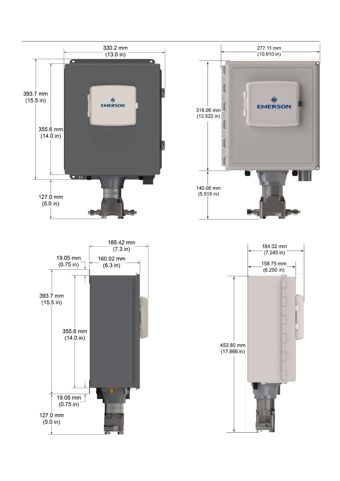
Abbildung 7. FB2200 (Aluminiumgehäuse) am Rohr montiert
Erdung
Die vordere Tür des FB2200 gemäß entweder Kapitel 2
der Bedienungsanleitung für den Emerson FB2200 Flow
Computer (Dok.-Nr. D301784X012) oder der
Kurzanleitung für den Emerson FB2200 Flow Computer
(Dok.-Nr. D301788X012) entfernen.
Wenn es in Ihrem Unternehmen keine speziellen
Erdungsvorschriften gibt, installieren Sie den FB2200
als ein „potentialfreies“ (ungeerdetes) System mittels
des Erdungsanschlusses und führen Sie das
Erdungskabel durch eine der Kabelverschraubungen.
Andernfalls die speziellen Erdungsverfahren Ihres
Unternehmens beachten. Wenn Sie eine Verbindung
zwischen einem geerdeten Gerät und einem EIA-232
(RS-232)-Anschluss herstellen, müssen Sie die
Spannungsversorgung des FB2200 erden.
Wenn das Gerät geerdet werden muss, sind die
folgenden Richtlinien zu beachten:
Wenn das Gerät mit einer Gleichspannungsquelle
versorgt wird, muss die Erdung an der
Spannungseinspeisung abgeschlossen werden.
Alle Geräteerdungsleiter einschließlich Kabel
oder in Kabelrohr verlegte Span-nungs-ver-sor-
gungs-lei-termüssen einen ununterbrochenen
elektrischen Pfad zur Spannungseinspeisung
bilden.
Unsachgemäße oder schlechte Erdung kann oft
Probleme verursachen, wie z. B. Erdschleifen im
System. Eine sachgemäße Erdung des FB2200
kann dazu beitragen, Einflüsse durch elektrisches
Rauschen auf den Betrieb des Gerätes zu
minimieren, und schützt vor
Überspannungen/Blitzschlag. Installieren Sie eine
Überspannungsschutzvorrichtung am
Betriebsunterbrecher in DC-Span-nungs-quel-len-
sys-te-men, um die installierte Ausrüstung vor
Blitzschlag und Stromstößen zu schützen.
Stellen Sie sicher, dass die Erdung des Flow
Computers vom kathodischen Schutz getrennt ist.
Die Ausführung der Erdungsinstallation für den
FB2200 hängt davon ab, ob die Rohrleitung über
einen kathodischen Schutz verfügt. Bei Rohrleitungen
mit kathodischem Schutz muss der FB2200 elektrisch
von der Rohrleitung isoliert bleiben. Alle
Schutzerdungen müssen eine Erdungsverbindung
oder eine Netzimpedanz von 25 Ohm oder weniger
aufweisen; die Messung ist mit einem Erdungstester
vorzunehmen.
Verkabelung der Spannungsversorgung
Den FB2200 durch die Leitungseinführungen an der Seite
des Gehäuses verdrahten. Die Anschlussklemmenblöcke
akzeptieren eine Verkabelung mit 2 mm
Durchmesser/3 mm2 oder kleiner. Anschluss der Leiter an
die abnehmbare Klemmenleiste:
Das Ende des Drahtes abisolieren (maximal 6 mm).
Das abisolierte Ende des Drahtes in die Klemme
unterhalb der Klemmschraube einführen.
Die Schraube festziehen.
Lassen Sie so wenig blanke Kabelenden wie möglich offen,
um Kurzschlüsse zu verhindern. Lassen Sie bei der
Herstellung der Verbindungen etwas Spiel, um
Spannungen zu vermeiden.
Verkabelung der Spannungsversorgung anschließen. Die
Beschreibungen für die Verdrahtung der
Spannungsversorgung in Kapitel 2 der Bedienungsanleitung
für den Emerson FB2200 Flow Computer (Dok.-Nr.
D301784X012) gründlich lesen.
Anschluss auf richtige Polarität überprüfen.
Anschlüsse zur Gleichspannungsversorgung herstellen:
Den Stecker des Anschlussklemmenblocks von der
Steckdose trennen.
Jedes blanke Kabelende in den entsprechenden
Anschluss einführen und sichern (siehe Abbildung 8).
Den Stecker des Anschlussklemmenblocks wieder in
die Steckerleiste einsetzen.
Anleitung zur sicheren Verwendung Emerson FB2200
Dok.-Nr. D301801X012
Juni 2021
www.Emerson.com/RemoteAutomation 5
Abbildung 8. Verkabelung zur DC-Spannungsversorgung
Detaillierte Anweisungen zum Anschließen der
Batterie finden Sie in der Kurzanleitung für den Emerson
FB2200 Flow Computer (Dok.-Nr. D301788X012).
Verkabelung mit Kommunikation und E/A
Schließen Sie die Verkabelung an den
Anschlussklemmenblöcken der E/A- und
Kommunikationsmodule an. Die Schaltpläne und
Erläuterungen finden Sie entweder in Abschnitt 2.8 in
Kapitel 2 der Bedienungsanleitung für den Emerson
FB2200 Flow Computer (Dok.-Nr. D301784X012) oder
in der Kurzanleitung für den Emerson FB2100 Flow
Computer (Dok.-Nr. D301788X012).
Wenn Sie die Kommunikation und die E/A verkabelt
haben, bringen Sie die vorderen und hinteren Deckel
wieder am FB2200 an.
Einschalten des FB2200
GEFAHR
Versuchen Sie nicht, dem Gerät Spannung zuzuführen
oder es von der Spannungsversorgung zu trennen,
während es sich in einem Ex-Bereich befindet.
Vergewissern Sie sich, dass die Umgebung nicht
gefährlich ist. Bei Nichtbeachtung kann es zu einer
Explosion kommen.
1. Spannung zuführen, um den FB2200 einzuschalten.
Wenn Sie die Spannungsversorgung einschalten,
leuchtet die Hintergrundbeleuchtung am HMI-Modul
ca. 5 Sekunden lang auf und erlischt wieder.
Während dieser Zeit wird die Datenbank initialisiert.
Nach ca. 45 Sekunden schaltet sich die
Hintergrundbeleuchtung am HMI wieder ein und
beginnt, Live-Daten anzuzeigen.
Überprüfen Sie die Verkabelung regelmäßig auf
Anzeichen von Verschleiß.
Konfigurieren des FB2200
Sie müssen die Field Tools Konfigurationssoftware von
Emerson (die FBxConnect™ mit einschließt) auf Ihrem
PC installieren, um den FB2200 für den Einsatz zu
konfigurieren. Anweisungen zur Installation und
Verwendung dieser Software finden Sie in der
Kurzanleitung für den Emerson FB2200 Flow Computer
(Dok.-Nr. D301788X012).
Zurücksetzen des FB2200
Falls Probleme auftreten, deren Ursache in der
Software vermutet wird, versuchen Sie, den FB2200
zurückzusetzen. Spezifische Anweisungen hierzu
finden Sie im Kapitel Service und Fehlersuche der
Betriebsanleitung für den Emerson FB2200 Flow
Computer (Dok.-Nr. D301784X012).
Hinweis: Beim Zurücksetzen gehen alle
Konfigurations- und Protokolldaten
verloren. Erstellen Sie (falls möglich) eine
Sicherheitskopie der Konfigurations- und
Protokolldaten, bevor Sie versuchen, das
Gerät zurückzusetzen.
Ersatzteile im FB2200 austauschen
Eine Liste der Teile, die der Benutzer selbst warten kann,
und ihre entsprechenden Feldersatzanleitungen finden Sie
in Tabelle 1.
Zurücksenden des FB2200
Falls Probleme auftreten, deren Ursache in der Hardware
vermutet wird, die Verkabelung prüfen. Falls die Probleme
weiterhin bestehen, wenden Sie sich zur Autorisierung der
Rückgabe an Ihr lokales Vertriebsbüro. So geben Sie Ihr
Gerät zurück:
1. Alle Konfigurationen und Daten sichern, bevor das
Gerät aus dem Prozess entfernt wird. Dann alle
Spannungsquellen vom Gerät trennen und die externe
Verkabelung vollständig entfernen.
2. Gerät deinstallieren.
3. Für den Versand oder die Lagerung das Gerät in einen
Karton legen.
Anleitung zur sicheren Verwendung Emerson FB2200
Dok.-Nr. D301801X012
Juni 2021
Kundendienst und technische Unterstützung
finden Sie unter www.Emerson.com/SupportNet.
Weltweite Firmenzentrale
Nordamerika/Lateinamerika:
Emerson Automation Solutions
Remote Automation Solutions
6005 Rogerdale Road
Houston, TX 77072, USA
Tel.: +1 281 879 2699 | Fax: +1 281 988 4445
www.Emerson.com/RemoteAutomation
© 2017-2021 Remote Automation Solutions, ein Geschäftsbereich von Emerson
Automation Solutions. Alle Rechte vorbehalten.
Diese Publikation dient nur zu Informationszwecken. Obwohl große Sorgfalt zur
Gewährleistung ihrer Exaktheit aufgewendet wurde, kann diese Publikation nicht zur
Ableitung von Garantie- oder Gewährleistungsansprüchen, ob ausdrücklicher Art oder
stillschweigend, hinsichtlich der in dieser Publikation beschriebenen Produkte oder
Dienstleistungen oder ihres Gebrauchs oder ihrer Verwendbarkeit herangezogen werden.
Remote Automation Solutions (RAS) behält sich das Recht vor, jederzeit und ohne
Vorankündigung die Konstruktion und technischen Daten seiner Produkte zu ändern oder
zu verbessern. Für alle Verkäufe gelten unsere (RAS) allgemeinen Geschäftsbedingungen,
die auf Anfrage zur Verfügung gestellt werden. Die Verantwortung bezüglich der richtigen
Auswahl, Verwendung oder Wartung von jeglichen Produkten liegt allein beim Käufer und
Endanwender.
Europa:
Emerson Automation Solutions
Remote Automation Solutions
Unit 1, Waterfront Business Park
Dudley Road, Brierley Hill
Dudley DY5 1LX UK
Tel.: +44 1384 487200
Naher Osten/Afrika:
Emerson Automation Solutions
Remote Automation Solutions
Emerson FZE
P.O. Box 17033
Jebel Ali Free Zone South 2
Dubai, Vereinigte Arabische Emirate
Tel.: +971 4 8118100 | Fax: +971 4 8865465
Asien/Pazifik:
Emerson Automation Solutions
Remote Automation Solutions
1 Pandan Crescent
Singapur 128461
Tel.: +65 6777 8211| Fax: +65 6777 0947
Remote Automation Solutions
Consignes de sécurité Emerson FB2200
réf. D301801X012
Juin 2021
Remote Automation Solutions
Calculateur de débit Emerson FB2200
Figure 1. Étiquette de l'Emerson FB2200
(Anti-étincelles avec capteur intégré)
Utilisez les présentes Instructions d'utilisation et de
sécurité (SUI) avec le Manuel d'instructions du calculateur de
débit Emerson FB2200 (réf. D301784X012). Consultez ce
manuel pour obtenir toutes les mesures de précaution,
explications d'installation et procédures de dépannage.
Pour obtenir une formation relative à ce produit,
contactez votre bureau commercial Emerson local.
Le calculateur de débit Emerson FB2200 (ou « FB2200 »)
avec une homologation ATEX peut être commandé avec
un module de communication ou E/S en option répertorié
dans la fiche de spécifications du calculateur de débit
Emerson FB2200 (réf. D301792X012).
Figure 2. Étiquette de l'Emerson FB2200
(Anti-étincelles sans capteur intégré)
Déclaration de conformité
Remote Automation Solutions déclare par la présente que
les calculateurs de débit FB2200 sont conformes aux
exigences essentielles et aux autres dispositions
applicables des Directives européennes 2014/30/UE (CEM)
et 2014/34/UE (ATEX).
Conditions particulières d’utilisation
Utiliser l’équipement dans une zone qui ne dépasse pas
le degré de pollution 2.
Prendre les précautions nécessaires pour s’assurer, en
cas de perturbation transitoire, que la tension
nominale ne dépasse pas 140 % de la tension nominale
de crête.
Les batteries au plomb-acide et l’énergie solaire ne
doivent pas être utilisées dans des applications ATEX.
Des tests d’impact sur l’écran ont été menés en
fonction des valeurs du Groupe II portant sur le faible
risque de danger mécanique, conformément au
tableau 13 des normes EN 60079-0:2012+A11:2013 et
CEI 600790 (6e édition). Installer les calculateurs de
débit équipés d’un écran dans des zones où le risque
d’impact est faible.
Pour les installations en zone 2, s’assurer que le
calculateur de débit est monté et utilisé de manière à
éviter tout risque de charges électrostatiques.
Le boîtier du FB2200 nécessite un outillage spécifique
pour s'ouvrir. Pour plus de détails, consulter la
rubrique Sécurité physique au Chapitre 1 du Manuel
d’instructions du calculateur de débit Emerson FB2200
(réf. D301784X012).
Consulter le tableau 1 pour les pièces de rechange.
Tableau 1. Pièces de rechange
Pièce de rechange
Référence du kit
Numéro de document
du Guide de
remplacement sur le
terrain
Carte d'E/S
d'extension à 8
canaux
400217010-KIT D301804X012
Carte d'E/S
d'extension à 6
canaux
400215010-KIT D301803X012
Indicateur du
module HMI
399379-01-0,
621627011-KIT,
399380-01-0,
621627020-KIT
D301822X012
Carte de terminaison
d'E/S
400210010-KIT,
358807010-KIT
D301805X012
Boîtier de CPU et
électronique
621673-01-0,
621674-01-0,
621675-01-0,
621676-01-0,
621678-01-0,
400209010-KIT,
399260-01-0,
399264-01-0,
400211010-KIT
D301803X012
Cellule Numéro de kit
variable
D301843X012
Accessoires de porte
399291-01-0,
399267-01-0,
399266-01-0,
621661010-KIT,
399394-00-0
D301825X012
Relais
395828-01-0
D301847X012
Pile bouton
395620-03-1
D301855X012
Consignes de sécurité Emerson FB2200
réf. D301801X012
Juin 2021
2 www.Emerson.com/RemoteAutomation
Spécifications
ALIMENTATION
Plage de fonctionnement : 10,5 à 30 V cc (puissance
maximale de 10 W).
BOITIER
Boîtier :
Aluminium à revêtement à poudre, avec porte
verrouillable
Fibre de verre moulé par compression, avec porte
verrouillable
ENVIRONNEMENT
Température de fonctionnement :
Anti-étincelles (Ex nA) : -25 °C à +55 °C.
Temp. de stockage :
-40 °C à +85 °C.
Humidité de fonctionnement :
5-95 % sans condensation,
conformément à la norme CEI 60068-2-3.
POIDS
6,94 kg (15.3 lbs) (boîtier en fibre de verre
10,75 kg (23.7 lbs) (boîtier en aluminium)
HOMOLOGATIONS
Évalué par rapport aux normes européennes suivantes
(CEM) :
EN 61326-1:2013 (Émissions)
EN 61326-2-3:2013 (Immunité)
Immunité
EN 61000-4-2 (Décharge électrostatique)
EN 61000-4-3 (Immunité aux champs rayonnés)
EN 61000-4-4 (Immunité aux transitoires rapides en
salves)
EN 61000-4-5 (Surtensions)
EN 61000-4-6 (Immunité aux radiofréquences
conduites)
EN 61000-4-8 (Immunité aux champs magnétiques de
puissance à impulsions)
EN 61000-4-17 (Immunité aux ondulations de tension)
EN 61000-4-29 (Immunité aux chutes et interruptions de
tension)
Évalpar rapport aux normes d'homologation suivantes :
Directive 2014/34/UE
EN 60079-0:2012+A11:2013
EN 60079-15:2010
Évalué par rapport aux normes suivantes (CEI) :
CEI 60079-0 (2011), 6e édition
CEI 60079-15 (2010), 4e édition
Marquages de produit pour emplacements dangereux :
Ex nA IIC T4 Gc (-25 °C Tamb +55 °C),
II 3 G
Cert. N° DEMKO 16 ATEX 1579X
DANGER
Si les unités sont installées dans une zone dangereuse,
assurez-vous que les étiquettes des composants
sélectionnés autorisent leur usage dans une telle zone.
L'installation et la maintenance ne doivent être
effectuées que lorsque la zone ne présente aucun risque.
L'installation ou la maintenance dans une zone
dangereuse peuvent entraîner des blessures ou des
dégâts matériels.
Mettez toujours le FB2200 hors tension avant toute
intervention sur le câblage. Toute intervention sur un
équipement sous tension pourrait entraîner des
blessures ou des dégâts matériels.
Pour éviter d'endommager les circuits lors d'une
intervention à l'intérieur de l'unité, prenez les précautions
pertinentes concernant les décharges électrostatiques,
notamment le port d'un bracelet antistatique.
Vérifiez la polarité de l'alimentation en entrée avant de
mettre le FB2200 sous tension. Toute intervention sur un
équipement sous tension pourrait entraîner des blessures
ou des dégâts matériels.
Les outils suivants sont nécessaires pour l'installation, la
maintenance et le dépannage :
Ordinateur PC exécutant Microsoft® Windows® 7
Professional, Windows 8.1 Pro ou Windows 10 Pro et
le logiciel de configuration Emerson Field Tools (avec
logiciel de configuration FBxConnect™).
Tournevis Philips (cruciformes) n° 1 et n° 2.
Tournevis à tête plate de 3 mm (1/8'').
Déballage
Le FB2200 vous est livré dans un carton. Sortez-le du
carton. Vérifiez soigneusement que toutes les pièces
figurant dans la nomenclature de livraison sont incluses.
Installation
1. Trouvez un emplacement convenable pour le FB2200.
Lors de la sélection d'un emplacement, assurez-vous
de bien vérifier tous les dégagements. Le boîtier du
FB2200 est conçu pour résister aux mauvaises
conditions climatiques. L'écran LCD en option doit
être visible et accessible à l'opérateur sur place.
Consignes de sécurité Emerson FB2200
réf. D301801X012
Juin 2021
www.Emerson.com/RemoteAutomation 3
Figure 3. Vue avant du FB2200 (boîtier en aluminium)
(avec capteur MVS intégré en option)
Figure 4. Vue latérale du FB2200 (boîtier en aluminium)
(avec capteur MVS intégré en option)
Figure 5. Vue avant du FB2200 (boîtier en fibre de verre)
(avec capteur MVS intégré en option)
Figure 6. Vue latérale du FB2200 (boîtier en fibre de verre)
(avec capteur MVS intégré en option)
Consignes de sécurité Emerson FB2200
réf. D301801X012
Juin 2021
4 www.Emerson.com/RemoteAutomation
2. Le FB2200 se monte sur un poteau ou un tuyau de
2 pouces (voir Figure 7) ; il peut également être monté
sur un mur ou un panneau au moyen des quatre trous
présents sur le boîtier et de fixations adéquates.
Figure 7. FB2200 (boîtier en aluminium) monté sur tuyau
Mise à la masse
Ouvrez la porte avant du FB2200, comme expliqué au
Chapitre 2 du Manuel d'instructions du calculateur de
débit Emerson FB2200 (réf. D301784X012) ou dans le
Guide de démarrage rapide du calculateur de débit
Emerson FB2200 (réf. D301788X012).
Si votre site n'observe aucune exigence de mise à la
terre, installez le FB2200 en tant que système
« flottant » (non relié à la terre) à l'aide du plot de masse
et acheminez le fil de masse via l'un des raccords de
conduit. Dans le cas contraire, observez les pratiques
spécifiques de mise à la terre de votre site. Cependant,
en cas de connexion entre un appareil mis à la terre et
un port EIA-232 (RS-232), reliez l'alimentation du
FB2200 à la ground.
Si vous devez mettre l'équipement à la terre, observez
les directives suivantes.
Lorsque l'équipement fonctionne sur une source
d'alimentation CC, le système de mise à la terre doit
se terminer au niveau du sectionneur d'entretien.
Tous les conducteurs de mise à la terre de
l'équipement, et notamment les fils ou les conduits
reliant les conducteurs, doivent fournir un trajet
électrique jusqu'au sectionneur d'entretien.
Une mise à la terre incorrecte ou médiocre peut
souvent être à l'origine de problèmes tels que
l'introduction de boucles de terre dans le système.
La mise à la terre correcte du FB2200 permet de
réduire les effets de bruit électrique lors du
fonctionnement de l'unité et protège contre la
foudre. Sur les systèmes d'alimentation en courant
continu, installez un dispositif de protection
contre les surtensions au niveau de l'interrupteur
de sectionnement pour protéger l'équipement
contre la foudre et les surtensions.
Assurez-vous que la masse du calculateur de débit
est séparée de la masse de protection cathodique.
La méthode de mise à la terre du FB2200 diffère selon
que la conduite est ou non pourvue d'une protection
cathodique. Sur les conduites dotées d'une protection
cathodique, le FB2200 doit être électriquement isolé
de la conduite. Toutes les prises de terre doivent avoir
une impédance de tige ou de grille de mise à la terre
égale ou inférieure à 25 ohms, conformément aux
mesures effectuées à l'aide d'un dispositif d'essai de la
mise à la terre.
Câblage à l'alimentation
Câblez le FB2200 via les raccords de conduit se trouvant
sur le bas du boîtier. Les borniers peuvent recevoir des
câbles de 2 mm de diamètre/3 mm2 maximum. Pour
raccorder le fil aux bornes de compression amovibles des
borniers :
Dénudez l'extrémité du câble (sur 6 mm maximum).
Introduisez l'extrémité dénudée du câble dans le
collier situé sous la vis de terminaison.
Serrez la vis.
Une longueur minimale de fil dénudé doit être exposée
afin d'éviter les courts-circuits. Laissez un peu de mou pour
éviter toute tension du câble.
Raccordez le câblage d'alimentation. Passez en revue les
descriptions de câblage d'alimentation au Chapitre 2 du
Manuel d'instructions du calculateur de débit Emerson
FB2200 (réf. D301784X012).
Vérifiez que la polarité de raccordement est correcte.
Pour les raccordements d'alimentation c.c. :
Déposez le connecteur de bornier de son support.
Insérez chaque extrémité de fil dénudé dans le
connecteur correspondant et fixez le câble (reportez-
vous aux Figure 8).
Ré-enfichez le connecteur de bornier de son support.
Figure 8. Câblage vers l'alimentation c.c.
Consignes de sécurité Emerson FB2200
réf. D301801X012
Juin 2021
www.Emerson.com/RemoteAutomation 5
Pour des instructions détaillées concernant la
connexion de la batterie, reportez-vous au Guide de
démarrage rapide du calculateur de débit Emerson
FB2200 (réf. D301788X012).
Câblage vers les modules de communications
et d'E/S
Reliez les câbles aux borniers des modules d'E/S et de
communication. Pour le schéma de câblage et des
explications, reportez-vous à la Section 2.8 du Chapitre 2
du Manuel d'instructions du calculateur de débit Emerson
FB2200 (réf. D301784X012) ou du Guide de démarrage
rapide du calculateur de débit Emerson FB2200
(réf. D301788X012).
Une fois que vous avez câblé les modules de
communication et d'E/S, fermez le couvercle du
FB2200 et fixez-le en place.
Mise sous tension du FB2200
DANGER
En zone dangereuse, ne cherchez pas à connecter ou à
déconnecter l'alimentation de l'unité. Assurez-vous que
la zone n'est pas dangereuse, au risque de provoquer
une explosion.
1. Pour démarrer le FB2200, mettez-le sous tension.
Lorsque vous appliquez l'alimentation, le
rétroéclairage du module HMI s'allume pendant
5 secondes environ, puis s'éteint. La base de données
commence à s'initialiser pendant ce temps. Au bout
de 45 secondes environ, le rétroéclairage du HMI
s'allume à nouveau et affiche des données en temps
réel.
Inspectez régulièrement le câblage afin de détecter
tout signe de détérioration.
Configuration du FB2200
Pour configurer le FB2200 à des fins d'utilisation, vous
devez installer le logiciel de configuration Field Tools
d'Emerson (avec FBxConnect™) sur votre ordinateur.
Pour des instructions concernant l'installation et
l'utilisation de ce logiciel, reportez-vous au Guide de
démarrage rapide du calculateur de débit Emerson
FB2200 (réf. D301788X012)
Réinitialisation du FB2200
Face à des problèmes potentiellement liés au logiciel,
essayez de réinitialiser le FB2200. Pour des instructions
spécifiques, reportez-vous au Chapitre Entretien et
dépannage du Manuel d'instructions du calculateur de
débit Emerson FB2200 (réf. D301784X012).
Remarque : Une réinitialisation entraînera la perte de
toutes les données de configuration et de
journalisation. Si possible, sauvegardez les
données de configuration et de
journalisation avant de procéder à une
réinitialisation, quelle qu'elle soit.
Remplacement des pièces du FB2200
Reportez-vous au tableau 1 pour une liste des pièces
réparables par l'utilisateur et de leurs guides de
remplacement de champ respectifs.
Retour du FB2200
En cas de problèmes potentiellement liés au matériel,
vérifiez le câblage. Si les problèmes persistent, contactez
votre bureau de vente local pour l'autorisation de renvoi.
Pour retourner l'appareil :
1. Sauvegardez la configuration et toutes les données
avant de débrancher l'appareil de la boucle de
procédé. Mettez l'appareil hors tension et
déconnectez tout câblage extérieur.
2. Désinstallez l'appareil.
3. Placez l'appareil dans une boîte à des fins d'expédition
ou de stockage.
Consignes de sécurité Emerson FB2200
réf. D301801X012
Juni 2021
Pour contacter le service clientèle et bénéficier d'une assistance technique,
consultez la page www.Emerson.com/SupportNet.
Siège social international
Amérique du Nord et Amérique latine:
Emerson Automation Solutions
Remote Automation Solutions
6005 Rogerdale Road
Houston, TX 77072 États-Unis.
T +1 281 879 2699 | F +1 281 988 4445
www.Emerson.com/RemoteAutomation
© 2017-2021 Remote Automation Solutions, une division d'Emerson Automation Solutions.
Tous droits réservés.
Cette publication est à titre informatif uniquement. Bien que tous les efforts aient été faits pour
vérifier l'exactitude des informations présentées dans ce document, ce dernier ne saurait être
considéré comme une garantie tacite ou explicite des produits ou services décrits quant à leur
utilisation ou leur applicabilité. Remote Automation Solutions (RAS) se réserve le droit de
modifier ou d'améliorer les conceptions ou les spécifications de ses produits à tout moment et
sans préavis. Toutes les ventes sont régies par les conditions générales de RAS, lesquelles sont
disponibles sur demande. RAS n'accepte aucune responsabilité quant au choix, à l'utilisation ou
à l'entretien d'un produit, laquelle incombe uniquement à l'acquéreur et/ou à l'utilisateur final.
Europe :
Emerson Automation Solutions
Remote Automation Solutions
Unit 1, Waterfront Business Park
Dudley Road, Brierley Hill
Dudley DY5 1LX UK
T +44 1384 487200
Moyen-Orient/Afrique:
Emerson Automation Solutions
Remote Automation Solutions
Emerson FZE
P.O. Box 17033
Jebel Ali Free Zone South 2
Dubai, Émirats Arabes Unis.
T +971 4 8118100 | F +971 4 8865465
Asie-Pacifique:
Emerson Automation Solutions
Remote Automation Solutions
1 Pandan Crescent
Singapour 128461
T +65 6777 8211| F +65 6777 0947
Remote Automation Solutions
  • Page 1 1
  • Page 2 2
  • Page 3 3
  • Page 4 4
  • Page 5 5
  • Page 6 6
  • Page 7 7
  • Page 8 8
  • Page 9 9
  • Page 10 10
  • Page 11 11
  • Page 12 12
  • Page 13 13
  • Page 14 14
  • Page 15 15
  • Page 16 16
  • Page 17 17
  • Page 18 18
  • Page 19 19
  • Page 20 20
  • Page 21 21
  • Page 22 22
  • Page 23 23
  • Page 24 24
  • Page 25 25
  • Page 26 26
  • Page 27 27
  • Page 28 28
  • Page 29 29
  • Page 30 30
  • Page 31 31
  • Page 32 32
  • Page 33 33
  • Page 34 34
  • Page 35 35
  • Page 36 36
  • Page 37 37
  • Page 38 38
  • Page 39 39
  • Page 40 40
  • Page 41 41
  • Page 42 42
  • Page 43 43
  • Page 44 44
  • Page 45 45
  • Page 46 46
  • Page 47 47
  • Page 48 48
  • Page 49 49
  • Page 50 50

Emerson D301801X012 Instruções de operação

Tipo
Instruções de operação