
119RW83
DFW
У
к
р
аїнська
UK
Hrv
a
t
s
ki
H
R
Magyar
HU
Nede
rl
a
n
ds
NL
Es
p
añol
E
S
D
eutsc
h
DE
Françai
s
FR
Р
у
сски
й
RU
E
n
g
lis
h
EN
P
o
l
s
ki
P
L
I
t
alia
n
o
I
T
Portu
g
uê
s
PT

L
190
46
101
DFW
RIOEDG01
RIOEDG01
DFW
RIOCTL01
DFW
DFI
DFW
DBCT
DFW
DBS01/02
11
1
3
2
1
7
9
8
4
5
6
6
10
11
11
12
10
Pag.
2
2 -
119RW83
119 R W83 ver.
1
1 01/2014

L N
L N
C
A
M
E
LN
LN - 30
30
LG
1
150
3
LP
2
4
5
Pag.
3
3 -
119RW83
119 R W83
ver.
1
1 01/2014

8
9
10
11
12
13
14
17
15
16
7
6
Pag.
4
4 -
119RW83
119 R W83 ver.
1
1 01/2014

2
1
3
5
4
Ø 2,5
6
7
1
2
3
4
10
11
20 mm
8
9
Pag.
5
5 -
119RW83
119 R W83
ver.
1
1 01/2014

2
C1
NCNOC
DFW
24V 0V NCNOC12V
NCNOC
11
2
C1
10
11
1
2
2
2
1
DFW
DFI
Pag.
6
6 -
119RW83
119 R W83 ver.
1
1 01/2014

NCNOC
NCNOC
2
1
IN1 IN2
DFW
RIOEDG01
RIOCTL01
NCNOC
DBCT
DFW
DBS01/02
Pag.
7
7 -
119RW83
119 R W83
ver.
1
1 01/2014

Pag.
8
8 -
119RW83
119 R W83 ver.
1
1 01/2014
IT
LEGENDA
Parti da leggere con attenzione.
Parti riguardanti la sicurezza.
Cosa comunicare all’utente.
RIFERIMENTI NORMATIVI
Came Cancelli Automatici S.p.A. è una azienda certificata
per i sistemi di gestione aziendale: qualità ISO 9001 e
ambientale ISO 14001.
Il prodotto in oggetto è conforme alle normative vigenti citate
nella dichiarazione di conformità.
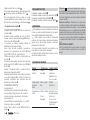
DESCRIZIONE
Questo prodotto è progettato e costruito da Came Cancelli
Automatici S.p.A. in conformità alle vigenti norme di
sicurezza, ed è certificato (PR&S n.04.363) per applicazione
in verticale.
Il bordo sensibile è costituito da un profilo di supporto in
alluminio e da un profilo e due tappi in gomma. All’interno
del profilo in gomma ci sono due meccanismi a leve snodate
unite da una fune in acciaio (ø 1,3 mm).
Destinazione d’uso
Il bordo sensibile di sicurezza è destinato alla protezione
dal rischio di schiacciamento e di intrappolamento. La
rilevazione avviene per contatto su tutta la lunghezza del
bordo, compresi i tappi.
Ogni installazione e uso difformi da quanto indicato nel
seguente manuale sono da considerarsi vietate.
Il presente manuale è destinato solamente al personale
tecnico professionale o persona qualificata per l’installazione.
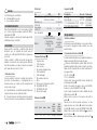
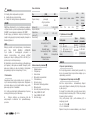
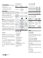
Dati tecnici
Tipo DFW DFI
Grado di protezione
(IP)
54 (fissato in verticale)
44 (fissato in orrizontale)
56
Alimentazione (V
)
- 12-24 AC / DC
Fusibile (mA)
- 63
Temperatura di
esercizio (°C)
-20 ÷ +55 -20 ÷ +55
Classe di isolamento
Materiali
Profilo in gomma
termoplastico CCA 48SHA
Tappi in gomma
termoplastico SEBS
60SHA
Leve snodate POM
Fune in acciaio
Scatola in
tecnopolimero
isolante
autoestinguente
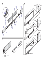
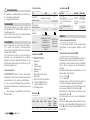
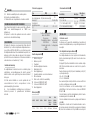
Componenti principali
1. Tappi in gomma
2. Profilo in gomma
3. Fune in acciaio
4. Meccanismo di aggancio fune
5. Profilo in alluminio
6. Staffa di fissaggio
7. Meccanismo porta-micro
8. Micro
9. Morsetto per il collegamento elettrico
10. Viti UNI6954 Ø 2,9x13
11. Viti UNI6954 Ø 3,9x13
12. Morsetto di fissaggio
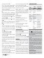
Dimensioni (mm)
DFW15 DFW17 DFW20 DFW25
DFW
(CM308+
CS181+
TMFW)
DFW
(CM308+
CS181H+
TMF6W)
1500 1700 2000 2500 4000 max 6000 max
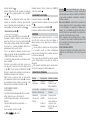
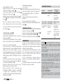
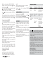
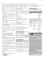
Impianto tipo
Collegamento Tipo cavo Sezione cavo
C - NC
FROR CEI
20-22 CEI
EN 50267-
2-1
2 X 0,5 mm2
C - NO - NC
3 X 0,5 mm2
C - NC Alimentazione 12-24 V
4 X 0,5 mm2
C - NC (Resistiva 8,2 KOhm)
2 X 0,5 mm2
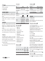
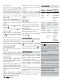
INSTALLAZIONE
Verifiche preliminari
Prima di procedere all’installazione è necessario verificare
che il punto di fissaggio del bordo sensibile sia su una
superficie idonea.
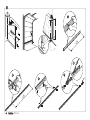
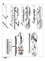
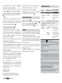
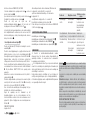
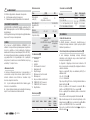
Preparazione del bordo sensibile
Per bordi sensibili di lunghezza non standard, determinare la
lunghezza nominale (LN) della zona da proteggere.
Attenzione! Nelle installazioni verticali, ridurre di 30 mm
la lunghezza nominale (LN) per evitare il contatto con il suolo.
Tagliare il profilo in gomma (LG) e il profilo in alluminio (LP)
nel seguente modo:
LG = LN - 285 mm ;
LP = LN - 40 mm .
Forare il profilo con una punta di Ø 3 mm su entrambi i lati
per il fissaggio dei tappi .
Inserire il meccanismo di aggancio fune nel profilo e
fissarlo con le due viti UNI6955 Ø 3,9x13 .
Inserire il profilo in gomma nel profilo in alluminio fino alla
battuta del meccanismo .
Infilare la fune in acciaio nel foro superiore del profilo in
gomma .
Sbloccare la leva del meccanismo porta-micro con una
leggera pressione verso il basso , inserire il meccanismo
nel profilo e fissarlo con le due viti UNI6955 Ø 3,9x13 .
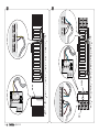
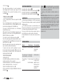
Infilare la fune in acciaio nel foro del morsetto
11
e inserire il
morsetto nella leva
12
.
Mettere in tensione la fune e avvitare il grano del morsetto
13

Pag.
9
9 -
119RW83
119 R W83
ver.
1
1 01/2014
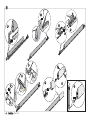
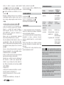
Tagliare la parte di fune in eccedenza
14
.
Inserire il tappo dalla parte del meccanismo di aggancio fune
15
e fissarlo con rondelle e viti UNI 6954 ø 3,9 x 13
16
.
Nota: nelle applicazioni verticali, per evitare che si formi
condensa all’interno del bordo sensibile, forare con punta
Ø 4 mm le tracce presenti sul tappo, prima di montarlo
17
.
Fissaggio del bordo sensibile
Predisporre un tubo corrugato (Ø 10 mm) necessario per il
collegamento .
Posizionare in modo equidistanti dal centro le staffe di
fissaggio, segnare e forare i punti di fissaggio . Fissare le
staffe con tasselli e viti Ø 4 mm .
Se necessario (es. strutture metalliche), utilizzare viti
autofilettanti a testa svasata Ø 3,9 mm.
Forare il retro del profilo in alluminio e prevedere un
passacavo per il passaggio del cavo elettrico . Negli
articoli: DFW15/17/20 il foro è già predisposto.
Utilizzare una sonda per facilitare lo scorrimento del cavo
nel profilo .
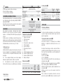
Posizionare il bordo sensibile sulle staffe, forare sui lati del
profilo con punta Ø 2,5 mm e fissarlo con le viti UNI 6954
Ø 2,9x13 .
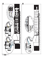
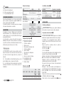
Eseguire i collegamenti elettrici a seconda del tipo di
impianto (vedi collegamenti elettrici).
Regolare la tensione della fune sul meccanismo porta-micro
con la vite di regolazione e verificare che il micro sia
posizionato correttamente: deve intervenire dopo una
deformazione di 20 mm max .
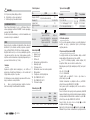
FUNZIONAMENTO CORRETTO:
- posizione iniziale ;
- punto di intervento del microinterrutore (20 mm dalla
posizione iniziale), tempo di risposta = 0,2 secondi ;
- posizione di massimo schiacciamento = 45 mm dalla
posizione iniziale ;
- tempo di ripristino della posizione iniziale = 2 secondi .
Fissare il meccanismo con la vite .
Inserire il tappo e fissarlo con viti UNI6954 Ø 3,9x13 e
rondelle
11
.
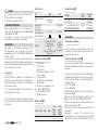
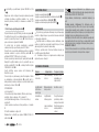
COLLEGAMENTI ELETTRICI
Collegamento al quadro comando
Collegamento al quadro comando e scheda di controllo (DFI)
Collegamento al modulo Wireless (RIOEDG01)
Collegamento al modulo trasmettitore da esterno (DBCT)
MANUTENZIONE
Prima di qualsiasi operazione di manutenzione, togliere la
tensione, per evitare possibili situazioni di pericolo causate
da accidentali movimentazioni dell’automazione.
Il bordo sensibile non necessità di manutenzioni
particolari, ma è buona norma controllare periodicamente
(ogni 6 mesi) lo stato del profilo in gomma e verificare il
funzionamento del dispositivo.
Se necessario pulire il dispositivo con un aspiratore o un
panno umido (non usare solventi o detergenti).
Eventuali modifiche al dispositivo di sicurezza, possono
determinare situazioni pericolose!
RISOLUZIONE DEI PROBLEMI
Problema Possibile causa Verifiche e rimedi
Il bordo non
interviene
Un cavo è
danneggiato
Rivolgersi
all’assistenza
(l’automazione non
deve essere usata)
Il bordo sensibile
interviene in
ritardo
Il micro è regolato
male
Rivolgersi
all’assistenza
L’automazione non
chiude.
Il bordo è sollecitato
Un cavo è
danneggiato
Verificare che non vi
sia oggetti appoggiati
al bordo o che
lo stesso non sia
deformato (Rivolgersi
all’assistenza).
Dichiarazione - Came Cancelli Automatici S.p.A. dichiara che
questo dispositivo è conforme ai requisiti essenziali e alle altre dispo-
sizioni pertinenti stabilite dalla direttiva 2006/42/CE e 2004/108/CE.
Su richiesta è disponibile la copia conforme all’originale della dichia-
razione di conformità.
Dismissione e smaltimento - Prima di procedere è sempre opportu-
no verifi care le normative specifi che vigenti nel luogo d’installazione.
I componenti dell’imballo (cartone, plastiche, etc.) sono assimilabili ai
rifi uti solidi urbani e possono essere smaltiti senza alcuna di coltà,
semplicemente e ettuando la raccolta di erenziata per il riciclaggio.
Altri componenti (schede elettroniche, batterie dei trasmettitori, etc.)
possono invece contenere sostanze inquinanti. Vanno quindi rimossi
e consegnati a ditte autorizzate al recupero e allo smaltimento degli
stessi.
NON DISPERDERE NELL’AMBIENTE!
I dati e le informazioni indicate in questo manuale sono da ritener-
si suscettibili di modifica in qualsiasi momento e senza obbligo di
preavviso.

Pag.
10
10 -
119RW83
119 R W83 ver.
1
1 01/2014
EN
LEGEND
Parts to read carefully.
Parts about safety.
What to tell users.
REFERENCE STANDARDS
Came Cancelli Automatici S.p.A. is certified for the: ISO
9001 quality and ISO 14001 environmental management
systems.
This product complies with the current rule and regulation
standards which are mentioned in the Certificate of
Conformity.
DESCRIPTION
This product is designed and built by Came Cancelli
Automatici S.p.A. in conformity with current legal safety
standards, and is (PR&S n.04.363) certified to be fitted
vertically.
The sensitive edge consists of an aluminium rail and two
rubber caps. Inside of the rubber edge there are two jointed-
lever mechanisms joined by a ø 1.3 mm stainless steel cable.
Intended use
The sensitive safety edge is designed to protect against
crushing and entrapment. Detection happens upon contact
along the entire length of the edge, caps included.
Any installation and/or use other than that indicated in
this manual is forbidden.
This manual is intended only for professional, technical
staff or certified installers.
Technical data
Type DFW DFI
Protection rating (IP)
54 (fitted vertically)
44 (fitted horizontally)
56
Power supply (V
)
- 12-24 AC / DC
Fuse (mA)
- 63
Operating
temperature (°C)
-20 ÷ +55 -20 ÷ +55
Insulations class
Materials
Thermoplastic rubber
edge CCA 48SHA
Thermoplastic rubber
caps SEBS 60SHA
POM jointed-levers
Stainless steel cable
Self-
extinguishing,
insulating, techno
polymer shell
Main components
1. Rubber caps
2. Rubber edge
3. Stainless steel cable
4. Cable anchoring mechanism
5. Aluminium edge
6. Fitting bracket
7. Microswitch-housing mechanism
8. Microswitch
9. Electrical connection terminal
10. UNI6954 Ø 2.9x13 Screws
11. UNI6954 Ø 3.9x13 Screws
12. Anchoring terminals
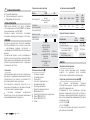
Dimensions (mm)
DFW15 DFW17 DFW20 DFW25
DFW
(CM308+
CS181+
TMFW)
DFW
(CM308+
CS181H+
TMF6W)
1500 1700 2000 2500 4000 max 6000 max
Standard system
Connection Cable type Cable section
C - NC
FROR CEI
20-22 CEI
EN 50267-
2-1
2 X 0.5 mm2
C - NO - NC
3 X 0.5 mm2
C - NC Power supply 12-24 V
4 X 0.5 mm2
C - NC (8.2 KOhm Resistance)
2 X 0.5 mm2
INSTALLING
Preliminary checks
Before installing, make sure the sensitive edge anchoring
point is on a suitable surface.
Setting up the sensitive edge
For non standard-length sensitive edges, measure the
nominal length (LN) of the area to make safe.
Warning! With vertical installations, reduce the nominal
length (LN) by 30 mm to prevent touching the floor.
Cut the rubber (LG) edge and the aluminium (LP) rail in in
the following way:
LG = LN - 285 mm ;
LP = LN - 40 mm .
Drill a hole in the rail using a Ø 3 mm bit on both sides to
fix the caps .
Fit the cable anchoring mechanism into the rail and fasten
it using the two UNI6955 Ø 3.9x13 screws .
Fit the rubber edge into the aluminium rail until it rests against
the mechanism stop .
Fit the steelcable into the upper hole of the rubber edge .
Release the micro-switch housing mechanism lever by
pressing lightly downwards , fit the mechanism into the rail
and fasten it using the two UNI6955 Ø 3.9x13 screws .
Fit the steel cable into the terminal
11
and fit the terminal
into the lever
12
.
Tensionthe cable and tighten the lug screw on the terminal
13
Cut any excess cable
14
.
Fit the cap on the end where the cable anchoring mechanism
is located
15
and fasten it using washers and UNI 6954 ø

Pag.
11
11 -
119RW83
119 R W83
ver.
1
1 01/2014
3.9 x 13 screws
16
.
Note: with vertical applications, to prevent condensation
from forming inside the sensitive edge, using a Ø 4 mm
bit drill holes in the cap where the marking are, before
assembling it
17
.
Fitting the sensitive edge
Set up a corrugated tube (Ø 10 mm) required for the
connection.
Place the fastening brackets at equal distances from the
center, mark and drill holes for fastening . Fasten the
brackets using wall plugs and Ø 4 mm screws.
If necessary, as with metal structures, use self-threading
flared Ø 3.9 mm screws .
Drill a hole in the back of the aluminium rail and fit a cable
gland for the electric cable to pass through . With items:
DFW15/17/20 the hole is predrilled.
Use a probe to ease the cable passage in the rail .
Place the sensitive edge onto the brackets, drill the sides of
the edge using a Ø 2.5 mm bit and fasten it using the UNI
6954 Ø 2.9x13 screws .
Make the required electrical connections depending on the
type of system (see Electrical Connections).
To adjust cable tension turn the adjustment screw on
the microswitch housing mechanism and make sure
the microswitch is properly fitted: it must activate after
deforming by 20 mm max .
PROPER WORKING ORDER:
- starting position ;
- microswitch activation point (20 mm from the starting
position), reaction time = 0.2 seconds ;
- maximum crushing point = 45 mm from the starting point ;
- return to starting position time = 2 seconds .
Fasten the mechanism using the screw .
Fit the cap and fasten it using the UNI6954 Ø 3.9x13 bolts
and washers
11
.
ELECTRICAL CONNECTIONS
Connecting to the control panel
Connecting to the control panel and control board (DFI)
Connecting to the Wireless module (RIOEDG01)
Connecting to the outdoor transmitter module (DBCT)
MAINTENANCE
Before doing any maintenance, cut off the power supply,
to prevent any hazardous situations caused by accidentally
activating operator.
The sensitive edge requires no special maintenance, but
it is better to periodically check (every six months) the state
of the rubber edge and working order of the device.
If necessary, clean the device using a vacuum cleaner or a
moist cloth (do not use either solvents or detergents).
Any modifications to the safety device, may result in a
hazard!
TROUBLESHOOTING
Problem Possible cause Checks and fixes
The edge does not
work
A cable is damaged Call for assistance
(stop using the
operator)
The sensitive edge
is slow in working
The microswitch
needs resetting
Call for assistance
The operator does
not shut.
The edge is engaged
A cable is damaged
Check that there are
no objects resting
against the edge or
that the edge is not
deformed (Call for
assistance).
Declaration - Came Cancelli Automatici S.p.A. declares that this
device conforms to the essential, pertinent requirements provided by
directives 2006/42/CE and 2004/108/CE.
An original copy of the declaration of conformity is available on re-
quest.
Dismantling and disposal - Always make sure you comply with local
laws beforedismantling and disposing of the product. The packaging
materials (cardboard, plastic, and so on) should be disposed of as so-
lid urban waste, and simply separated from other waste for recycling.
Whereas other components (electronic boards, batteries, transmit-
ters and so on) may contain hazardous pollutants. These must the-
refore be disposed of by authorized, certifi ed professional services.
DO NOT DISPOSE OF IN NATURE!
The data and information in this manual may be changed at any time
and without notice.

Pag.
12
12 -
119RW83
119 R W83 ver.
1
1 01/2014
FR
LÉGENDE
Parties à lire attentivement.
Parties concernant la sécurité.
Ce que l'utilisateur doit savoir.
RÉFÉRENCES NORMATIVES
Came Cancelli Automatici S.p.A. est une société certifiée
pour les systèmes de gestion de la qualité ISO 9001 et de
gestion environnementale ISO 14001.
Le produit en question est conforme aux normes en vigueur
citées dans la déclaration de conformité.
DESCRIPTION
Ce produit a été conçu et fabriqué par la société Came
Cancelli Automatici S.p.A. conformément aux normes de
sécurité en vigueur, et a été certifié (PR&S n° 04.363) pour
une application verticale.
Le bord sensible se compose d'un profilé de support en
aluminium, d'un profilé et de deux embouts en caoutchouc.
Le profilé en caoutchouc contient deux mécanismes à leviers
articulés unis par un câble en acier (ø 1,3 mm).
Utilisation prévue
Le bord sensible de sécurité est une protection contre le
risque d'écrasement et de coincement. La détection a lieu
par contact sur toute la longueur du bord, y compris les
embouts.
Toute installation et toute utilisation autres que celles
qui sont indiquées dans ce manuel sont interdites.
Le présent manuel s'adresse uniquement au personnel
technique professionnel ou aux personnes préposées à
l'installation.
Données techniques
Type DFW DFI
Degré de protection
(IP)
54 (fixé verticalement)
44 (fixé horizontalement)
56
Alimentation (V
)
- 12-24 AC / DC
Fusible (mA)
- 63
Température de
fonctionnement (°C)
-20 ÷ +55 -20 ÷ +55
Classe d'isolation
Matériaux
Profilé en caoutchouc
thermoplastique CCA
48SHA
Embouts en caoutchouc
thermoplastique SEBS
60SHA
Leviers articulés POM
Câble en acier
Boîtier en
technopolymère
isolant auto-
extinguible
Composants principaux
1. Embouts en caoutchouc
2. Profilé en caoutchouc
3. Câbles en acier
4. Mécanisme de fixation du câble
5. Profilé en aluminium
6. Étrier de fixation
7. Mécanisme porte-minirupteur
8. Minirupteur
9. Borne de connexion électrique
10. Vis UNI6954 Ø 2,9x13
11. Vis UNI6954 Ø 3,9x13
12. Bride de fixation
Dimensions (mm)
DFW15 DFW17 DFW20 DFW25
DFW
(CM308+
CS181+
TMFW)
DFW
(CM308+
CS181H+
TMF6W)
1500 1700 2000 2500 4000 max. 6000 max.
Installation standard
Connexion Type câble Section câble
C - NF
FROR CEI
20-22 CEI
EN 50267-
2-1
2 X 0,5 mm²
C - NO - NF
3 X 0,5 mm²
C - NF Alimentation 12-24 V
4 X 0,5 mm²
C - NF (Résistive 8,2 KOhms)
2 X 0,5 mm²
INSTALLATION
Contrôles préliminaires
Avant l'installation, s'assurer que le point de fixation du
bord sensible se trouve bien sur une surface adéquate.
Préparation du bord sensible
Pour des bords sensibles d'une longueur non standard,
déterminer la longueur nominale (LN) de la zone à protéger.
Attention ! En cas d'application verticale, réduire la
longueur nominale (LN) de 30 mm pour éviter tout contact
avec le sol.
Couper le profilé en caoutchouc (LG) et le profilé en
aluminium (LP) comme suit :
LG = LN - 285 mm ;
LP = LN - 40 mm .
Percer le profilé à l'aide d'une mèche d'un diamètre de 3 mm
des deux côtés pour la fixation des embouts .
Introduire le mécanisme de fixation du câble dans le profilé
et le fixer à l'aide des deux vis UNI6955 Ø 3,9x13 .
Introduire le profilé en caoutchouc dans le profilé en
aluminium jusqu'à la butée du mécanisme .
Faire passer le câble en acier à travers le trou supérieur du
profilé en caoutchouc .
Débloquer le levier du mécanisme porte-minirupteur en
poussant légèrement vers le bas , introduire le mécanisme
dans le profilé et le fixer à l'aide des deux vis UNI6955
Ø 3,9x13 .
Faire passer le câble en acier à travers le trou de la bride
11
et introduire la bride dans le levier
12
.
Tendre le câble et visser le goujon de la bride
13
Couper la

Pag.
13
13 -
119RW83
119 R W83
ver.
1
1 01/2014
partie de câble en trop
14
.
Introduire l'embout du côté du mécanisme de fixation du
câble
15
et le fixer à l'aide derondelles et de vis UNI 6954
ø 3,9 x 13
16
.
Remarque : en cas d'application verticale, pour éviter la
formation de condensation à l'intérieur du bord sensible,
percer à l'aide d'une mèche d'un diamètre de 4 mm aux
endroits indiqués sur l'embout avant de l'appliquer
17
.
Fixation du bord sensible
Prévoir un tuyau ondulé (Ø 10 mm) pour la connexion .
Positionner les brides de fixation à la même distance par
rapport au centre, tracer et percer les points de fixation .
Fixer les brides à l'aide de chevilles et de vis Ø 4 mm .
Si nécessaire (ex. : structures métalliques), utiliser des vis
autotaraudeuses à tête noyée Ø 3,9 mm.
Percer le dos du profilé en aluminium et prévoir un passe-
câble pour le passage du câble électrique . Sur les articles
: DFW15/17/20 le trou a déjà été effectué.
Se servir d'une sonde pour faciliter le glissement du câble
dans le profilé .
Positionner le bord sensible sur les brides, percer sur les
côtés du profilé à l'aide d'une mèche d'un diamètre de Ø
2,5 mm et le fixer à l'aide des vis UNI 6954 Ø 2,9x13 .
Effectuer les branchements électriques en fonction du type
d'installation (voir branchements électriques).
Régler la mise en tension du câble sur le mécanisme
porte-minirupteur à l'aide de la vis de réglage et s'assurer
que le minirupteur est bien positionné correctement : il doit
intervenir après une déformation de 20 mm max. .
FONCTIONNEMENT CORRECT :
- position initiale ;
- point d'intervention du minirupteur (20 mm de la position
initiale), temps de réponse = 0,2 seconde ;
- position d'écrasement maximum = 45 mm de la position
initiale ;
- temps de rétablissement de la position initiale = 2
secondes .
Fixer le mécanisme à l'aide de la vis .
Introduire l'embout et le fixer à l'aide de vis UNI6954 Ø
3,9x13 et de rondelles
11
.
BRANCHEMENTS ÉLECTRIQUES
Connexion à l'armoire de commande
Connexion à l'armoire de commande et à la carte de contrôle
(DFI)
Connexion au module Wireless (RIOEDG01)
Connexion au module émetteur d'extérieur (DBCT)
ENTRETIEN
Avant toute autre opération d'entretien, il est conseillé
de mettre hors tension pour éviter toute situation de
danger provoquée par des déplacements accidentels de
l'automatisme.
Le bord sensible ne requiert aucun entretien particulier.
Il est cependant conseillé de contrôler périodiquement
(tous les 6 mois) l'état du profilé en caoutchouc ainsi que le
fonctionnement du dispositif.
Si nécessaire, nettoyer le dispositif à l'aide d'un aspirateur
ou d'un chiffon humide (ne pas utiliser de solvants ou
détergents).
Toute éventuelle modification apportée au dispositif de
sécurité peut provoquer des situations dangereuses !
RÉSOLUTION DES PROBLÈMES
Problème Cause possible Contrôles et remèdes
Le bord
n'intervient pas
Un câble est
endommagé
S'adresser à
l'assistance (ne pas
utiliser l'automatisme)
Le bord sensible
intervient en retard
Le minirupteur est
mal réglé
S'adresser à
l'assistance
L’a u tom ati sme
n'effectue pas la
fermeture
Le bord sensible
est sollicité
Un câble est
endommagé
S'assurer qu'aucun
objet n'est posé sur le
bord ou contrôler que
ce dernier n'est pas
déformé (S'adresser à
l'assistance)
Déclaration - Came Cancelli Automatici S.p.A. déclare que ce
dispositif est conforme aux exigences essentielles et aux dispositions
pertinentes établies par les directives 2006/42/CE et 2004/108/CE.
La copie conforme à l'original de la déclaration de conformité est
disponible sur demande.
Mise au rebut et élimination - Avant d’e ectuer ces opérations, il est
toujours recommandé de vérifi er les normes spécifi ques en vigueur
sur le lieu d’installation. Les composants de l’emballage (carton,
plastiques, etc.) sont assimilables aux déchets urbains solides et
peuvent être éliminés sans aucune di culté, en procédant tout sim-
plement à la collecte di érenciée pour le recyclage.
D’autres composants (cartes électroniques, piles des émetteurs,
etc.) peuvent par contre contenir des substances polluantes. Il faut
donc les désinstaller et les remettre aux entreprises autorisées à les
récupérer et à les éliminer.
NE PAS JETER DANS LA NATURE !
Les données et les informations contenues dans ce manuel sont sus-
ceptibles de subir des modifications à tout moment et sans aucun
préavis.

Pag.
14
14 -
119RW83
119 R W83 ver.
1
1 01/2014
DE
ZEICHENERKLÄRUNG
Abschnitte, die sorgfältig durchgelesen werden müssen.
Sicherheitsrelevante Abschnitte.
Benutzerrelevante Abschnitte.
BEZUGSNORMEN
Came Cancelli Automatici S.p.A. wendet im Betrieb das
nach ISO 9001 und ISO 14001 zertifizierte Qualitäts- und
Umweltmanagement an.
Dieses Produkt entspricht den in der Konformitätserklärung
zitierten und derzeit gültigen Richtlinien.
BESCHREIBUNG
Dieses Produkt wurde von der Came Cancelli Automatici
S.p.A. gemäß den geltenden Sicherheitsvorschriften
entwickelt und hergestellt und ist für die senkrechte Montage
zertifiziert (PR&S n.04.363).
Die Sicherheitsleiste besteht aus einem Halteprofil aus
Aluminium sowie einem Gummiprofil mit zwei Gummi-
Endkappen. Im innern des Gummiprofils befinden sich zwei
Seilzug-Hebelmechaniken, die mit einem Stahlseil (ø 1,3 mm)
miteinander verbunden sind.
Verwendungszweck
Die Sicherheitsleiste dient dem Schutz vor Quetschgefahr
und Einklemmen. Die Erfassung erfolgt durch Kontakt auf der
gesamten Länge der Leiste, darunter auch die Endkappen.
Alle, von den in der Montageanleitung beschriebenen,
abweichenden Installationen bzw. Verwendungszwecke sind
unzulässig.
Diese Anleitung ist ausschließlich für Fachleute und
Monteure gedacht.
Technische Daten
Typ DFW DFI
Schutzart (IP)
54 (senkrecht montiert)
44 (waagerecht montiert)
56
Betriebsspannung
(V
)
- 12-24 AC / DC
Sicherung (mA)
- 63
Betriebstemperatur
(°C)
-20 ÷ +55 -20 ÷ +55
Isolierklasse
Materialien
Thermoplastisches
Gummiprofil CCA 48SHA
Endkappen aus
thermoplastischem
Gummi SEBS 60SHA
Gelenkhebel POM
Stahlseil
Selbstlöschendes,
isolierendes
Gehäuse aus
Technopolymer
Hauptbestandteile
1. Endkappen aus Gummi
2. Gummiprofil
3. Stahlseil
4. Seilzugmechanik
5. Aluminiumprofil
6. Halterung
7. Mikroschalter-Haltemechanik
8. Mikroschalter
9. Klemme für elektrischen Anschluss
10. Schrauben UNI6954 Ø 2,9x13
11. Schrauben UNI6954 Ø 3,9x13
12. Befestigungsklemme
Maße (mm)
DFW15 DFW17 DFW20 DFW25
DFW
(CM308+
CS181+
TMFW)
DFW
(CM308+
CS181H+
TMF6W)
1500 1700 2000 2500 max. 4000 max. 6000
Standardanlage
Anschluss Kabeltyp Kabelstärke
C - NC
FROR CEI
20-22 CEI
EN 50267-
2-1
2 X 0,5 mm2
C - NO - NC
3 X 0,5 mm2
C - NC Betriebsspannung
12-24 V
4 X 0,5 mm2
C - NC (Widerstand 8,2
KOhm)
2 X 0,5 mm2
MONTAGE
Vorher vorzunehmende Kontrollen
Vor der Montage überprüfen, dass die Verankerung der
Sicherheitsleiste auf einer geeigneten Oberfläche befestigt
wird.
Vorbereitung der Sicherheitsleiste
Bei Sicherheitsleisten mit nicht standardgemäßer Länge, die
Nennlänge (LN) des abzusichernden Bereichs abmessen.
Achtung! Bei senkrecht montierten Leisten, die Nennlänge
(LN) um 30 mm verringern, um den Bodenkontakt zu
vermeiden.
Das Gummiprofil (LG) und das Aluminiumprofil (LP) in der
folgenden Weise durchschneiden:
LG = LN - 285 mm ;
LP = LN - 40 mm .
Auf beiden Seiten des Profils mit einem Ø 3 mm Bohrer ein
Loch für die Befestigung der Endkappen bohren .
Die Seilzugmechanik in das Profil stecken und mit den
zwei Schrauben UNI6955 Ø 3,9x13 befestigen .
Das Gummiprofil bis zum Einrasten der Mechanik in das
Aluminiumprofil stecken .
Das Stahlseil durch das obere Loch auf dem Gummiprofil
einziehen .
Den Hebel der Mikroschalter-Haltemechanik durch leichten
Druck nach unten entriegeln , die Mechanik in das Profil
stecken und mit den zwei Schrauben UNI6955 Ø 3,9x13
befestigen .

Pag.
15
15 -
119RW83
119 R W83
ver.
1
1 01/2014
Das Stahlseil durch das Loch in der Klemme ziehen
11
und
die Klemme in den Hebel stecken
12
.
Das Stahlseil spannen und den Stift in der Klemme
festschrauben
13
Überflüssiges Stahlseil abschneiden
14
.
Die Endkappe auf das Ende mit der Seilzugmechanik stecken
15
und mit Unterlegscheiben und Schrauben UNI 6954 ø 3,9
x 13
16
.
Anmerkung: Um bei vertikaler Montage die Kondensation
im Innern der Sicherheitsleiste zu vermeiden, vor der
Montage mit einem Ø 4 mm Bohrer die auf der Endkappe
vorhandenen Einprägungen durchbohren
17
.
Befestigung der Sicherheitsleiste
Ein Wellrohr (Ø 10 mm) für den Anschluss verlegen .
In gleicher Entfernung von der Mitte, die beiden Halterungen
anlegen, anzeichnen und die für die Befestigung nötigen
Löcher bohren . Die Halterungen mit Dübeln und
Schrauben Ø 4 mm befestigen .
Wenn nötig (z.B. bei Metallstrukturen), selbstschneidende
Senkschrauben Ø 3,9 mm verwenden.
Auf der Rückseite des Aluminiumprofils ein Loch bohren und
eine Kabelverschraubung als Kabeldurchlass einlegen . In
den Artikeln: DFW15/17/20 ist das Loch schon vorgebohrt.
Um das Einziehen des Kabels in das Profil zu erleichtern eine
Einziehhilfe verwenden .
Die Sicherheitsleiste auf den Halterungen anlegen, mit
einem Bohrer Ø 2,5 mm seitlich im Profil Löcher bohren
und mit den Schrauben UNI 6954 Ø 2,9x13 befestigen .
Die elektrischen Anschlüsse dem Anlagentyp entsprechend
(siehe elektrische Anschlüsse) vornehmen.
Die Zugspannung des Seils auf der
Mikroschalter-Haltemechanik mit der Einstellschraube
einstellen und überprüfen, dass der Mikroschalter richtig
eingelegt wurde: er muss nach einer Verformung von max.
20 mm schalten .
KORREKTER BETRIEB:
- Anfangsstellung ;
- Einschaltpunkt des Mikroschalters (20 mm von der
Anfangsstellung), Reaktionszeit = 0,2 Sekunden ;
- max. Quetschpunkt = 45 mm von der Anfangsstellung ;
- Rückstellzeit zur Anfangsstellung = 2 Sekunden .
Die Mechanik mit der Schraube befestigen .
Die Endkappe aufstecken und mit Schrauben UNI6954 Ø
3,9x13 und Unterlegscheiben befestigen
11
.
ELEKTRISCHE ANSCHLÜSSE
Anschluss an die Steuerung
Anschluss an die Steuerung und an die Kontroll-Platine (DFI)
Anschluss an das drahtlose Modul (RIOEDG01)
Anschluss an Aufputz-Funksender (DBCT)
WARTUNG
Vor Wartungsmaßnahmen jeglicher Art, Stromzufuhr
unterbrechen, um jegliche, durch die ungewollte Bewegung
der Anlage verursachte Gefahr zu vermeiden.
Die Sicherheitsleiste bedarf keiner besonderen Wartung,
doch es ist empfehlenswert den Zustand des Gummiprofils
und den Betrieb der Sicherheitsvorrichtung regelmäßig (alle
6 Monate) zu kontrollieren.
Wenn nötig die Vorrichtung mit einem Staubsauger oder
einem feuchten Tuch reinigen (keine Lösungs- oder
Reinigungsmittel verwenden).
Eventuelle Veränderungen der Sicherheitsvorrichtung
können Gefahrsituationen herbeiführen!
STÖRUNGSBESEITIGUNG
Störung Mögliche Ursache
Kontrollen und Abhil-
femaßnahmen
Die
Sicherheitsleiste
schaltet nicht
Das Kabel ist
beschädigt
An den Kundendienst
wenden (der Antrieb
darf nicht verwendet
werden)
Die
Sicherheitsleiste
schaltet zu spät
Der Mikroschalter ist
falsch eingestellt
An den Kundendienst
wenden
Der Antrieb
schließt nicht
Die Sicherheitsleiste
ist betätigt
Ein Kabel ist
beschädigt
Überprüfen, dass
keine Gegenstände auf
der Sicherheitsleiste
aufliegen bzw. dass die
Leiste nicht verformt ist
(an den Kundendienst
wenden).
Herstellererklärung - Die Came Cancelli
Automatici S.p.A. bestätigt, dass dieses Gerät den grundlegenden
Anforderungen und entsprechenden Bestimmungen der Richtlinien
2006/42/EG und 2004/108/EG
entspricht.
Auf Anfrage ist eine dem Original entsprechende Kopie der Konfor-
mitätserklärung verfügbar.
Abbau und Entsorgung - Vor der Entsorgung ist es empfehlenswert,
sich über die am Installationsort geltenden Vorschriften zu infor-
mieren. Die Bestandteile der Verpackung (Pappe, Kunststo usw.)
können getrennt gesammelt mit dem normalen Hausmüll entsorgt
werden.
Weitere Bestandteile (Platinen, Handsenderbatterien usw.) können
Schadsto e enthalten. Sie müssen dementsprechend entfernt und
in zugelassenen Fachbetrieben entsorgt werden.
NICHT IN DIE UMWELT GELANGEN LASSEN!
Die in dieser Anleitung angegebenen Daten und Informationen kön-
nen jederzeit, ohne Vorankündigung abgeändert werden.

Pag.
16
16 -
119RW83
119 R W83 ver.
1
1 01/2014
ES
LEYENDA
Partes que se tienen que leer con mucha atención.
Partes pertinentes a la seguridad
Qué hay que comunicar al usuario.
REFERENCIAS NORMATIVAS
Came Cancelli Automatici S.p.A. es una empresa con
sistema certificado de gestión empresarial: calidad ISO 9001
y medioambiente ISO 14001.
Este producto es conforme a las normas vigentes
mencionadas en la declaración de conformidad.
DESCRIPCIÓN
Este producto ha sido diseñado y fabricado por Came
Cancelli Automatici S.p.A. con arreglo a las normas de
seguridad vigentes y está certificado (PR&S n.04.363) para
montarlo en vertical.
El borde sensible se compone de un perfil de soporte, de
aluminio, y de un perfil y dos tapas de goma. Dentro del perfil
en goma hay dos mecanismos de palancas articuladas unidas
por un cordel de acero (ø 1,3 mm).
Uso previsto
El borde sensible de seguridad ha sido diseñado para
proteger del riesgo de aplastamiento y de atrapamiento. La
detección tiene lugar por contacto en toda la longitud del
borde, incluidas las tapas.
Se prohíbe una instalación o un uso diferentes de
cuanto indicado en este manual.
El presente manual está destinado solamente al personal
técnico profesional o a una persona cualificada para efectuar
la instalación.
Datos técnicos
Tipo DFW DFI
Grado de protección
(IP)
54 (montado en vertical)
44 (montado en
horizontal)
56
Alimentación (V
)
- 12-24 AC / DC
Fusible (mA)
- 63
Temperatura de
funcionamiento (°C)
-20 ÷ +55 -20 ÷ +55
Clase de aislamiento
Materiales
Perfil de goma
termoplástica CCA 48SHA
Tapas de goma
termoplástica SEBS
60SHA
Palancas articuladas POM
Cordel de acero
Caja de
tecnopolímero
aislante
autoextinguible
Componentes principales
1. Tapas de goma
2. Perfil de goma
3. Cordel de acero
4. Mecanismo de enganche del cordel
5. Perfil de aluminio
6. Soporte de fijación
7. Mecanismo porta-microinterruptor
8. Microinterruptor
9. Borne para el conexionado eléctrico
10. Tornillos UNI6954 Ø 2,9x13
11. Tornillos UNI6954 Ø 3,9x13
12. Mordaza de fijación
Medidas (mm)
DFW15 DFW17 DFW20 DFW25
DFW
(CM308+
CS181+
TMFW)
DFW
(CM308+
CS181H+
TMF6W)
1500 1700 2000 2500 4000 máx. 6000 máx.
Instalación típica
Conexión
Tipo de
cable
Sección del
cable
C - NC
FROR CEI
20-22 CEI
EN 50267-
2-1
2 X 0,5 mm2
C - NA - NC
3 X 0,5 mm2
C - NC Alimentación 12-24 V
4 X 0,5 mm2
C - NC (Resistiva 8,2 kOhm)
2 X 0,5 mm2
INSTALACIÓN
Verificaciones preliminares
Antes de proceder a efectuar la instalación es necesario
comprobar que el punto de fijación del borde sensible esté
sobre una superficie idónea.
Preparación del borde sensible
Para los bordes sensibles de longitud no estándar, hay que
determinar la longitud nominal (LN) de la zona que se tiene
que proteger.
¡Atención! En las instalaciones verticales, reducir 30 mm
la longitud nominal (LN) para evitar el contacto con el suelo.
Cortar el perfil de goma (LG) y el perfil de aluminio (LP) de
la siguiente manera:
LG = LN - 285 mm ;
LP = LN - 40 mm .
Taladrar el perfil con una broca de Ø 3 mm en ambos lados
para fijar las tapas .
Introducir el mecanismo de enganche del cordel en el perfil
y fijarlo con los dos tornillos UNI6955 Ø 3,9x13 .
Introducir el perfil de goma en el perfil de aluminio hasta
llegar al tope del mecanismo .
Introducir el cordel de acero en el agujero superior del perfil
de goma .
Desbloquear la palanca del mecanismo porta-
microinterruptor con una ligera presión hacia abajo ,
introducir el mecanismo en el perfil y fijarlo con los dos

Pag.
17
17 -
119RW83
119 R W83
ver.
1
1 01/2014
tornillos UNI6955 Ø 3,9x13 .
Introducir el cordel de acero en el agujero de la mordaza
11
e introducir la abrazadera en la palanca
12
.
Tensar el cable y atornillar el prisionero de la mordaza
13
Cortar la parte de cordel que sobra
14
.
Introducir la tapa por la parte del mecanismo de enganche
del cordel
15
y fijarla con arandelas y tornillos UNI 6954 ø
3,9 x 13
16
.
Nota: en las aplicaciones verticales, para evitar que se
formen condensados dentro del borde sensible, taladrar
con una broca de Ø 4 mm
las marcas presentes en la tapa,
antes de montarla
17
.
Fijación del borde sensible
Preparar un tubo corrugado (Ø 10 mm), necesario para
efectuar la conexión .
Posicionar de manera equidistante del centro los estribos de
fijación, marcar y taladrar los puntos de fijación . Fijar los
estribos con tacos y tornillos Ø 4 mm .
Si fuese necesario (por ej. estructuras metálicas), utilizar
tornillos autorroscantes con cabeza avellanada de Ø 3,9 mm.
Taladrar el dorso del perfil de aluminio y prever un
prensaestopas para hacer pasar el cable eléctrico . En
los artículos: DFW15/17/20 el agujero ya está predispuesto.
Utilizar una guía para facilitar el deslizamiento del cable en
el perfil .
Posicionar el borde sensible sobre los estribos, taladrar en
los lados del perfil con una broca de Ø 2,5 mm y fijarlo
con los tornillos UNI 6954 Ø 2,9x13 .
Efectuar las conexiones eléctricas con arreglo al tipo de
instalación (véanse las conexiones eléctricas).
Ajustar la tensión del cordel en el mecanismo porta-
microinterruptor utilizando el tornillo de regulación
y comprobar que el microinterruptor esté colocado
correctamente: tiene que actuar después de una deformación
de 20 mm como máx. .
FUNCIONAMIENTO CORRECTO:
- posición inicial ;
- punto de actuación del microinterruptor (20 mm desde la
posición inicial), tiempo de respuesta = 0,2 segundos ;
- posición de aplastamiento máximo = 45 mm desde la
posición inicial ;
- tiempo de restablecimiento de la posición inicial = 2
segundos .
Fijar el mecanismo mediante el tornillo .
Introducir la tapa y fijarla con tornillos UNI6954 Ø 3,9x13 y
arandelas
11
.
CONEXIONES ELÉCTRICAS
Conexión con el cuadro de mando
Conexión con el cuadro de mando y tarjeta de control (DFI)
Conexión con el módulo inalámbrico (RIOEDG01)
Conexión con el módulo emisor para exteriores (DBCT)
MANTENIMIENTO
Antes de efectuar cualquier tipo de operación de
mantenimiento, cortar la corriente eléctrica para evitar
eventuales situaciones de peligro causadas por movimientos
accidentales de la automatización.
El borde sensible no necesita mantenimientos especiales,
pero es buena norma comprobar periódicamente (cada
6 meses) el estado del perfil de goma y comprobar el
funcionamiento del dispositivo.
Si fuese necesario limpiar el dispositivo utilizar una
aspiradora o un paño húmedo (no utilizar disolventes o
detergentes).
Eventuales modificaciones del dispositivo de seguridad,
¡pueden llevar a situaciones peligrosas!
SOLUCIÓN DE PROBLEMAS
Problema Causa posible
Verificaciones y
soluciones
El borde no actúa Un cable está
dañado
Dirigirse al servicio
técnico (no se
tiene que utilizar la
automatización)
El borde sensible
actúa con retraso
El microinterruptor
está mal ajustado
Dirigirse al servicio
técnico
La automatización
no cierra
El borde está
esforzado
Un cable está
dañado
Comprobar que
no haya objetos
apoyados sobre el
borde o que el borde
no esté deformado
(Dirigirse al servicio
técnico).
Declaración - Came Cancelli Automatici S.p.A. declara que este
dispositivo cumple con los requisitos esenciales y con las demás
disposiciones pertinentes establecidas por las Directivas 2006/42/
CE y 2004/108/CE.
A petición está disponible la copia conforme al original de la decla-
ración de conformidad.
Desguace y eliminación - Antes de operar es siempre conveniente
verifi car las normativas específi cas vigentes en el lugar donde se
efectuará la instalación. Los elementos del embalaje (cartón, plás-
tico, etc.) se pueden considerar como residuos sólidos urbanos y
pueden eliminarse sin ninguna difi cultad, efectuando simplemente la
recogida selectiva para su posterior reciclaje.
Otros elementos (tarjetas electrónicas, baterías de los emisores, etc.)
podrían contener sustancias contaminantes. Por consiguiente se de-
ben quitar de los equipos y entregar a empresas autorizadas para su
recuperación o eliminación.
¡NO TIRAR AL MEDIOAMBIENTE!
Los datos y las informaciones presentados en este manual pueden
ser modificados en cualquier momento y sin obligación de previo
aviso.

Pag.
18
18 -
119RW83
119 R W83 ver.
1
1 01/2014
NL
LEGENDA
Delen die aandachtig moeten worden gelezen.
Delen die de veiligheid betre en.
Informatie die aan de gebruiker moet worden verstrekt.
NORMEN WAARNAAR WORDT VERWEZEN
Came Cancelli Automatici is houder van de ISO-certificaten
9001 voor kwaliteitsmanagement en 14001 voor
milieubeheer.
Dit product is conform alle geldende normen die vermeld
worden in de conformiteitsverklaring.
BESCHRIJVING
Dit product is ontworpen en gebouwd door Came Cancelli
Automatici S.p.A. conform de geldende veiligheidsnormen en
is gecertificeerd (PR&S n.04.363) voor verticale toepassing.
De veiligheidsrand bestaat uit een aluminium steunprofiel, een
rubberen profiel en twee rubberen doppen. In het rubberen
profiel zitten twee mechanismen met scharnierende hendels
verbonden door een staalkabel (ø 1,3 mm).
Gebruiksbestemming
De veiligheidsrand is bedoeld voor de bescherming tegen
verbrijzelings- en beknellingsgevaar. De detectie gebeurt
middels contact over de gehele lengte van de rand, inclusief
de doppen.
Elke andere installatie en soorten gebruik die niet
overeenstemmen met wat is voorgeschreven in deze
gebruiksaanwijzing, zijn verboden.
Deze handleiding is uitsluitend voor professioneel
technisch personeel of gekwalificeerde installateurs
bestemd.
Technische gegevens
Type DFW DFI
IP-
Beschermingsgraad
54 (verticaal bevestigd)
44 (horizontaal bevestigd)
56
Voeding (V
)
- 12-24 AC / DC
Zekering (mA)
- 63
Bedrijfstemperatuur
(°C)
-20 ÷ +55 -20 ÷ +55
Isolatieklasse
Materialen
Profiel van thermoplastisch
rubber CCA 48SHA
Doppen van
thermoplastisch rubber
SEBS 60SHA
Scharnierende hendels
POM
Staalkabel
Behuizing
van isolerend,
zelfdovend
technopolymeer
Hoofdcomponenten
1. Rubberen doppen
2. Rubberen profiel
3. Staalkabel
4. Kabelbevestigingsmechanisme
5. Aluminium profiel
6. Bevestigingsbeugel
7. Houdermechanisme voor microschakelaar
8. Microschakelaar
9. Klem voor de elektrische aansluiting
10. Schroeven UNI6954 Ø 2,9x13
11. Schroeven UNI6954 Ø 3,9x13
12. Bevestigingsklem
Maten (mm)
DFW15 DFW17 DFW20 DFW25
DFW
(CM308+
CS181+
TMFW)
DFW
(CM308+
CS181H+
TMF6W)
1500 1700 2000 2500 4000 max 6000 max
Standaardinstallatie
Aansluiting Kabeltype
Kabeldoors-
nede
C - NC
FROR CEI
20-22 CEI
EN 50267-
2-1
2 X 0,5 mm2
C - NO - NC
3 X 0,5 mm2
C - NC Voeding 12-24 V
4 X 0,5 mm2
C - NC (resistief 8,2 KOhm)
2 X 0,5 mm2
INSTALLATIE
Controles vooraf
Alvorens over te gaan tot de installatie moet gecontroleerd
worden of de veiligheidsrand op een geschikt oppervlak wordt
bevestigd.
De veiligheidsrand gereedmaken
Voor veiligheidsranden met een lengte die niet standaard is,
dient u de nominale lengte (LN) van de te beschermen zone
te bepalen.
Opgelet! Bij verticale installaties moet de nominale lengte
(LN) 30 mm verkleind worden om contact met de grond te
voorkomen.
Zaag het rubberen profiel (LG) en het aluminium profiel (LP)
op de volgende wijze:
LG = LN - 285 mm ;
LP = LN - 40 mm .
Boor aan beide zijden in het profiel met een boor van Ø 3 mm
voor de bevestiging van de doppen .
Steek het mechanisme voor de kabelbevestiging in het
profiel en zet het vast met de twee schroeven UNI6955
Ø 3,9x13 .
Steek het rubberen profiel in het aluminium profiel tot aan de
eindaanslag van het mechanisme .
Steek de staalkabel in de bovenste opening van het rubberen
profiel .
Ontgrendel de hendel van het houdermechanisme van de
microschakelaar door hem zachtjes naar beneden te drukken
, steek het mechanisme in het profiel en bevestig het

Pag.
19
19 -
119RW83
119 R W83
ver.
1
1 01/2014
met twee schroeven UNI6955 Ø 3,9x13 .
Steek de staalkabel in de opening van de klem
11
en steek
de klem in de hendel
12
.
Span de kabel en draai het schroefje van de klem aan.
13
Verwijder het overtollige deel van de kabel
14
.
Plaats de dop aan de zijde van het
kabelbevestigingsmechanisme
15
en zet hem vast met
borgringen en schroeven UNI 6954 ø 3,9 x 13
16
.
Let op: bij verticale toepassingen dienen, om condensvorming
in de veiligheidsrand te voorkomen, met een boor van Ø 4
mm de markeringen op de dop te worden geboord, alvorens
de dop te monteren
17
.
De veiligheidsrand bevestigen
Plaats een ribbelbuis (Ø 10 mm) die benodigd is voor de
aansluiting .
Plaats de bevestigingsbeugels op gelijke afstand van het
midden, markeer en boor op de bevestigingspunten .
Bevestig de beugels met pluggen en schroeven Ø 4 mm .
Gebruik indien nodig (bijv. bij metalen constructies)
zelftappende schroeven met verzonken kop van Ø 3,9 mm.
Boor in de achterkant van het aluminium profiel en zorg voor
een kabelwartel voor de doorvoer van de elektriciteitskabel
. Bij de artikelen: DFW15/17/20 is de opening reeds
aanwezig.
Gebruik een sonde om de kabeldoorvoer in het profiel te
vergemakkelijken .
Plaats de veiligheidsrand op de beugels, boor aan de zijden
van het profiel met een boor van Ø 2,5 mm en bevestig
hem met de schroeven UNI 6954 Ø 2,9x13 .
Voer de elektrische aansluitingen uit naargelang het type
installatie (zie elektrische aansluitingen).
Regel de spanning van de staalkabel op het
houdermechanisme van de microschakelaar met de
stelschroef en controleer of de microschakelaar correct
geplaatst is: hij moet ingrijpen na een vervorming van max.
20 mm .
CORRECTE WERKING:
- beginpositie ;
- interventiepunt van de microschakelaar (20 mm van de
beginpositie), reactietijd = 0,2 seconden ;
- positie van maximale beknelling = 45 mm van de
beginpositie ;
- resettijd van de beginpositie = 2 seconden .
Bevestig het mechanisme met de schroef .
Plaats de dop en bevestig hem met schroeven UNI6954 Ø
3,9x13 en borgringen
11
.
ELEKTRISCHE AANSLUITINGEN
Aansluiting aan de stuurkast
Aansluiting aan de stuurkast en besturingskaart (DFI)
Aansluiting aan de draadloze module (RIOEDG01)
Aansluiting aan de zendermodule voor opbouw (DBCT)
ONDERHOUD
Voordat er onderhoudswerkzaamheden worden
uitgevoerd moet de stroom worden uitgeschakeld om
gevaarlijke situaties te voorkomen door onverwachte
bewegingen van de installatie.
De veiligheidsrand behoeft geen speciaal onderhoud,
maar het is verstandig om regelmatig (elke 6 maanden) de
staat van het rubberen profiel te checken en de werking van
de inrichting te controleren.
Reinig indien nodig de inrichting met een stofzuiger of
vochtige doek (gebruik geen oplos- of reinigingsmiddelen).
Eventuele wijzigingen aan de veiligheidsinrichting kunnen
voor gevaarlijke situaties zorgen!
PROBLEMEN OPLOSSEN
Probleem Mogelijke oorzaak
Controles en oplos-
singen
De rand grijpt
niet in
Er is een kabel
beschadigd
Raadpleeg de
technische service
(de automatisering
mag niet worden
gebruikt)
De veiligheidsrand
reageert te traag
De microschakelaar
is niet goed afgesteld
Raadpleeg de
technische service
De automatisering
sluit niet.
De rand wordt door
iets in werking gezet
Er is een kabel
beschadigd
Controleer of er geen
objecten tegen de
rand leunen en of de
rand niet vervormd
is (raadpleeg de
technische service).
Verklaring - Came Cancelli Automatici S.p.A. verklaart hierbij dat
de apparatuur voldoet aan de essentiële vereisten en andere ter zake
doende voorschriften van de richtlijnen 2006/42/EG en 2004/108/
EG.
Op verzoek is een kopie van de verklaring van overeenstemming
verkrijgbaar.
Ontmantelen en slopen - Voordat u dit doet, dient u altijd de vo-
orschriften terzake te controleren die gelden in het land van instal-
latie. De verpakkingselementen (karton, plastic, enzovoort) worden
ingedeeld als normaal stedelijk afval en moeten alleen worden ge-
scheiden.
Andere componenten zoals printplaten, zenderbatterijen, enzovoort
kunnen vervuilende sto en bevatten. Lever deze in bij erkende afval-
bedrijven voor de verwerking van schadelijk afval.
VERVUIL HET MILIEU NIET MET AFVAL!
De in deze gebruiksaanwijzing vermelde gegevens en informatie kun-
nen op elk ogenblik en zonder verplichting tot waarschuwing vooraf
worden gewijzigd.

Pag.
20
20 -
119RW83
119 R W83 ver.
1
1 01/2014
PT
LEGENDA
Partes que devem ser lidas com atenção.
Partes relativas à segurança.
O que comunicar ao utilizador.
REFERÊNCIAS DE NORMAS TÉCNICAS
Came Cancelli Automatici S.p.A. é uma empresa certificada
pelo sistema de gestão empresarial: qualidade ISO 9001 e
ambiental ISO 14001.
O produto em objecto respeita as normas técnicas vigentes
citadas na declaração de conformidade.
DESCRIÇÃO
Este produto foi projectado e fabricado Came Cancelli
Automatici S.p.A. de acordo com as normas de segurança
vigentes, e é certificado (PR&S n.04.363) para aplicação na
vertical.
A borda sensível é constituída por um perfil de suporte em
alumínio e por um perfil e duas tampas de borracha. Dentro do
perfil em borracha existem dois mecanismos com alavancas
articuladas unidas por um cabo de aço (ø 1,3 mm).
Destinação de uso
A borda sensível de segurança tem a função de protecção do
risco de esmagamento e de estrangulamento. A identificação
é feito por contacto no comprimento total da borda, inclusive
das tampas.
Toda e qualquer instalação ou uso diverso daquele
indicado no seguinte manual, considera-se proibido.
Este manual deve ser usado somente por pessoal
técnico profissional ou pessoa qualificada para a instalação.
Dados técnicos
Tipo DFW DFI
Grau de protecção
(IP)
54 (fixado na vertical)
44 (fixado na horizontal)
56
Alimentação (V
)
- 12-24 AC / DC
Fusível (mA)
- 63
Temperatura de
funcionamento (°C)
-20 ÷ +55 -20 ÷ +55
Classe de
isolamento
Materiais
Perfil em borracha termo-
plástica CCA 48SHA
Tampas em borracha
termo-plástica SEBS
60SHA
Alavanca articulada POM
Cabos em aço
Caixa em termo-
polímero isolante
auto-extinguível
Componentes principais
1. Tampas em borracha
2. Perfil em borracha
3. Cabo em aço
4. Mecanismo de engate de cabe
5. Perfil em alumínio
6. Suporte de fixação
7. Mecanismo porta-micro
8. Micro
9. Terminal para ligação eléctrica
10. Parafusos UNI6954 Ø 2,9x13
11. Parafusos UNI6954 Ø 3,9x13
12. Grampo de fixação
Dimensões (mm)
DFW15 DFW17 DFW20 DFW25
DFW
(CM308+
CS181+
TMFW)
DFW
(CM308+
CS181H+
TMF6W)
1500 1700 2000 2500 4000 máx. 6000 máx.
Instalação tipo
Ligações
Tipo de
cabo
Secção do
cabo
C - NC
FROR CEI
20-22 CEI
EN 50267-
2-1
2 X 0,5 mm2
C - NO - NC
3 X 0,5 mm2
C - NC Alimentação 12-24 V
4 X 0,5 mm2
C - NC (Resistiva 8,2 KOhm)
2 X 0,5 mm2
INSTALAÇÃO
Controlos preliminares
Antes de continuar a instalação é preciso verificar que
o ponto de fixação da borda sensível esteja sobre uma
superfície apropriada.
Preparação da borda sensível
Para bordas sensíveis de comprimento não standard,
determine o comprimento nominal (LN) da área a ser
projectada.
Atenção! Nas instalações verticais, reduz em 30 mm o
comprimento nominal (LN) para evitar o contacto com o solo.
Corte o perfil em borracha (LG) e o perfil em alumínio (LP)
da seguinte forma:
LG = LN - 285 mm ;
LP = LN - 40 mm .
Fure o perfil com uma ponta de Ø 3 mm nos dois lados para
a fixação das tampas .
Introduza o mecanismo de enganche do cabo no perfil e
fixe-o com dois parafusos UNI6955 Ø 3,9x13 .
Introduza o perfil em borracha no perfil em alumínio até tocar
no mecanismo .
Introduza o cabo em aço no furo superior do perfil em
borracha .
Solte a alavanca do mecanismo porta-micro com uma
pressão leve para baixo , introduza o mecanismo no perfil
A página está carregando...
A página está carregando...
A página está carregando...
A página está carregando...
A página está carregando...
A página está carregando...
A página está carregando...
A página está carregando...
A página está carregando...
A página está carregando...
A página está carregando...
A página está carregando...
-
 1
1
-
 2
2
-
 3
3
-
 4
4
-
 5
5
-
 6
6
-
 7
7
-
 8
8
-
 9
9
-
 10
10
-
 11
11
-
 12
12
-
 13
13
-
 14
14
-
 15
15
-
 16
16
-
 17
17
-
 18
18
-
 19
19
-
 20
20
-
 21
21
-
 22
22
-
 23
23
-
 24
24
-
 25
25
-
 26
26
-
 27
27
-
 28
28
-
 29
29
-
 30
30
-
 31
31
-
 32
32


CAME DFW20 Manual do usuário
- Tipo
- Manual do usuário
- Este manual também é adequado para
em outras línguas
- español: CAME DFW20 Manual de usuario
- français: CAME DFW20 Manuel utilisateur
- italiano: CAME DFW20 Manuale utente
- English: CAME DFW20 User manual
- русский: CAME DFW20 Руководство пользователя
- Nederlands: CAME DFW20 Handleiding
- Deutsch: CAME DFW20 Benutzerhandbuch
- polski: CAME DFW20 Instrukcja obsługi
Artigos relacionados
-
CAME DF Guia de instalação
-
-
-
-
-
-
-
-
-
Outros documentos
-
Chamberlain 1EML Manual do proprietário
-
EINHELL BT-EH 1000 Manual do proprietário
-
 Roger Technology BARK/02 Barrier skirt Manual do usuário
-
Chamberlain LiftMaster ART300 K Manual do proprietário
-
-
Metabo Guide rail 1500 mm Instruções de operação
-
Bahco BWTPMSS9 Manual do usuário
-
 Roger Technology ALED Boom lights Instruções de operação
-
Dometic FlyTec FT100 Instruções de operação
-

