Dometic FlyTec FT200 Instruções de operação
- Tipo
- Instruções de operação

WINDOWS & DOORS
BLINDS
FlyTec FT200
Flyscreen for sliding doors
Operating manual . . . . . . . . . . . . . . . . . . . . . 8
Insektenschutz für Schiebetüren
Bedienungsanleitung . . . . . . . . . . . . . . . . . 15
Moustiquaire pour portes
coulissantes
Notice d’utilisation . . . . . . . . . . . . . . . . . . .23
Protección contra insectos para
puertas corredizas
Instrucciones de uso . . . . . . . . . . . . . . . . . . 31
Proteção contra insetos para portas
deslizantes
Manual de instruções . . . . . . . . . . . . . . . . .39
Zanzariera per porte scorrevoli
Istruzioni per l’uso . . . . . . . . . . . . . . . . . . . .47
Hor voor schuifdeuren
Gebruiksaanwijzing . . . . . . . . . . . . . . . . . . 55
Net til skydedøre
Betjeningsvejledning . . . . . . . . . . . . . . . . . 63
Insektsskydd för skjutdörrar
Bruksanvisning . . . . . . . . . . . . . . . . . . . . . . 71
Insektsbeskyttelse for skyvedører
Bruksanvisning . . . . . . . . . . . . . . . . . . . . . . 79
Hyttyssuoja liukuoviin
Käyttöohje . . . . . . . . . . . . . . . . . . . . . . . . . . 86
Москитная сетка для сдвижных
дверей
Инструкция по эксплуатации . . . . . . . . . . 93
Ochrona przed insektami dla drzwi
przesuwnych
Instrukcja obsługi . . . . . . . . . . . . . . . . . . . 101
Protihmyzová sieťka pre posuvné
dvere
Návod na obsluhu. . . . . . . . . . . . . . . . . . . 109
Síť proti hmyzu na posuvné dveře
Návod k obsluze . . . . . . . . . . . . . . . . . . . . 117
Rovarvédő tolóajtókhoz
Használati utasítás. . . . . . . . . . . . . . . . . . . 124
EN
DE
FR
ES
PT
IT
NL
DA
SV
NO
FI
RU
PL
SK
CS
HU
FT200-IOM-EMEA16.book Seite 1 Dienstag, 7. Januar 2020 11:31 11

FT200-IOM-EMEA16.book Seite 2 Dienstag, 7. Januar 2020 11:31 11

Dometic FlyTec FT200
3
3
5
4
1
8
2
6
7
1
C = 15 mm
A =
18 mm
B = 3 mm
5
4
3
2
≥ 20 mm
40 mm
1
Y
X
2
FT200-IOM-EMEA16.book Seite 3 Dienstag, 7. Januar 2020 11:31 11

Dometic FlyTec FT200
4
1.
4.
3.
2.
3
4
FT200-IOM-EMEA16.book Seite 4 Dienstag, 7. Januar 2020 11:31 11

Dometic FlyTec FT200
5
1.
2.
3.
5
6
2.
1.
7
FT200-IOM-EMEA16.book Seite 5 Dienstag, 7. Januar 2020 11:31 11

Dometic FlyTec FT200
6
7x
8
1
2
4.
6.
5.
2.
1.
3.
25 N
25 N
9
FT200-IOM-EMEA16.book Seite 6 Dienstag, 7. Januar 2020 11:31 11

Dometic FlyTec FT200
7
20 - 25 N
0
FT200-IOM-EMEA16.book Seite 7 Dienstag, 7. Januar 2020 11:31 11

EN
Explanation of symbols Dometic FlyTec FT200
8
Please read this instruction manual carefully before first use, and store it in
a safe place. If you pass on the product to another person, hand over this
instruction manual along with it.
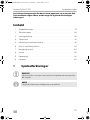
Contents
1 Explanation of symbols. . . . . . . . . . . . . . . . . . . . . . . . . . . . . . . . . . . . . . . . . . .8
2 Safety instructions . . . . . . . . . . . . . . . . . . . . . . . . . . . . . . . . . . . . . . . . . . . . . . .8
3 Scope of delivery . . . . . . . . . . . . . . . . . . . . . . . . . . . . . . . . . . . . . . . . . . . . . . .9
4 Intended use . . . . . . . . . . . . . . . . . . . . . . . . . . . . . . . . . . . . . . . . . . . . . . . . . . .9
5 Installing the flyscreen. . . . . . . . . . . . . . . . . . . . . . . . . . . . . . . . . . . . . . . . . . .10
6 Using the flyscreen . . . . . . . . . . . . . . . . . . . . . . . . . . . . . . . . . . . . . . . . . . . . .13
7 Cleaning and maintenance. . . . . . . . . . . . . . . . . . . . . . . . . . . . . . . . . . . . . . .13
8 Warranty . . . . . . . . . . . . . . . . . . . . . . . . . . . . . . . . . . . . . . . . . . . . . . . . . . . . .14
9 Disposal . . . . . . . . . . . . . . . . . . . . . . . . . . . . . . . . . . . . . . . . . . . . . . . . . . . . . .14
10 Versions . . . . . . . . . . . . . . . . . . . . . . . . . . . . . . . . . . . . . . . . . . . . . . . . . . . . . .14
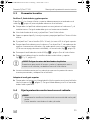
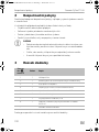
1 Explanation of symbols
A
I
2 Safety instructions
Please observe the safety instructions and stipulations issued by the vehicle
manufacturer and service workshops.
The manufacturer accepts no liability for damage in the following cases:
•
Faulty assembly or connection
•
Damage to the product resulting from mechanical influences
NOTICE!
Indicates a situation that, if not avoided, can result in property damage.
NOTE
Supplementary information for operating the product.
FT200-IOM-EMEA16.book Seite 8 Dienstag, 7. Januar 2020 11:31 11

EN
Dometic FlyTec FT200 Scope of delivery
9
•
Alterations to the product without express permission from the manufacturer
•
Use for purposes other than those described in the operating manual
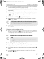
A
NOTICE!
•
If you do not have sufficient technical knowledge for installing
components in vehicles, you should have a specialist install the fly-
screen in your vehicle.
•
Check whether the dimensions of the flyscreen fit your vehicle.
•
Installation of the flyscreen requires two people.
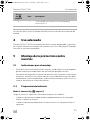
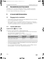
3Scope of delivery
The screws for fastening on the vehicle are not included in the scope of delivery.
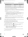
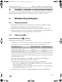
4 Intended use
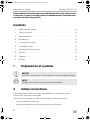
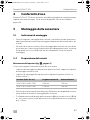
The Dometic FlyTec FT200 is a flyscreen for sliding doors on camper vans which can
be slid or folded horizontally. For available versions see the table, page 14.
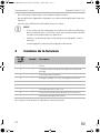
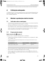
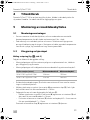
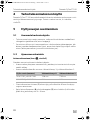
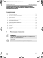
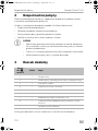
No. in
fig. 1,
page 3
Quantity Description
1 1 Skirting board
2 1 Cassette profile with flyscreen and guide cables
3 1 C pillar cover
4 7 Blind rivet (4 x 8 mm with stainless steel mandrel)
5 1 Fastening screw M5 x 30 mm and M5 nut
6 1 Guide rail above
7 1 Safety clip and screw M2.5 x 6
8 1 Deflection screw M4 with safety clip and screw M2.5 x 6
– Installation and operating manual
FT200-IOM-EMEA16.book Seite 9 Dienstag, 7. Januar 2020 11:31 11

EN
Installing the flyscreen Dometic FlyTec FT200
10
5 Installing the flyscreen
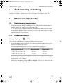
5.1 Notes on installation
•
Before installing the flyscreen, check whether any vehicle components could be
damaged by the installation of the flyscreen (such as cupboards).
•
For safety reasons, note the location of existing wiring harnesses, wires and other
components within the installation area, in particular those which are not visible,
when installing the flyscreen (when drilling or screwing, etc.).
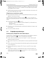
5.2 Preparing the vehicle
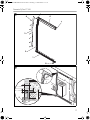
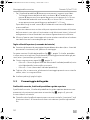
Measuring the opening (fig. 2, page 3)
Please observe the following instructions when measuring:
•
The installation opening should not have been made smaller through added
strips, coverings, fixtures, etc.
•
The installation opening must have the minimum width of X and minimum height
of Y:
•
Behind the rear sealing of the door (1), there needs to be a minimum of 40 mm
space for the flyscreen to be installed.
•
There needs to be a space with a width of A = 18 mm between the outer edge of
the bodywork floor (4) and fitted cabinets (2) (e.g. kitchen).
•
The skirting board (5) needs the following space:
– There needs to be a space with a width of A = 18 mm between the outer edge
of the bodywork floor (4) and the edge of the interior fittings base (3).
– A space with a height of B = 3 mm and a depth of C = 15 mm needs to be
available from the edge of the interior fittings base (3).
You may need to adapt fitted cabinets (2) and the interior fittings base (3).
•
The flyscreen must be screwed directly to the sheet-metal bodywork at the top
and not just on the panelling or the interior fittings. It is usually sufficient to screw
it on to the base of the interior fittings.
FlyTec version (ref. no.) Minimum width X Minimum height Y
9104117297 and 9104117296 1298 mm 1765 mm
9104117387 and 9104117388 1128 mm 1492 mm
FT200-IOM-EMEA16.book Seite 10 Dienstag, 7. Januar 2020 11:31 11

EN
Dometic FlyTec FT200 Installing the flyscreen
11
➤ Measure the installation opening in your vehicle and check whether the
dimensions of the flyscreen fit your vehicle.
Trimming the opening (depending on the vehicle)
➤ If necessary, remove add-on parts that interfere (such as bottom end strips or
bodywork) in the installation opening.
To be able to install the skirting board (fig. 1 1, page 3) flush, you may need to trim
the existing fixtures (such as floors or cabinets).
➤ Mark the following (fig. 2, page 3):
– Size A = 18 mm (width of the bottom part of the skirting board), measured
from the edge of the sheet-metal bodywork
– Size B = 3 mm (height of the skirting board).
➤ If necessary, trim the existing fixtures with a suitable tool, such as an oscillating
saw.
➤ Smooth and clean the cut edges.
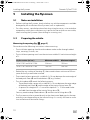
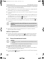
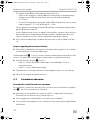
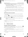
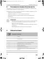
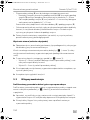
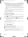
5.3 Pre-installing the rails
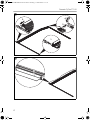
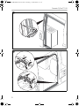
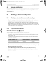
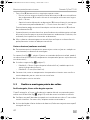
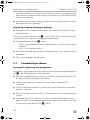
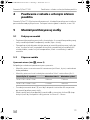
Cassette profile, skirting board and upper guide rail
The cassette profile, skirting board and upper guide rail must be assembled lying on
the ground (fig. 3, page 4) before being placed in the vehicle.
➤ Check whether the cover profile can be inserted between the C pillar and interior
fittings. You may need to adapt the contour by trimming.
➤ Guide the lower slider of the handle strip along with the cassette profile into the
skirting board.
➤ Pull the cassette and handle strip apart by a bit and then slide the cassette profile
onto the nose on the skirting board.
➤ Secure the cassette profile with the screw (M5 x 30 mm) and M5 nut on the upper
guide rail.
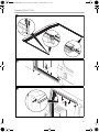
➤ Insert the cover for the C pillar into the cassette so that the drill holes are located
one above the other and secure the two components with three blind rivets
(4 x 8 mm with stainless steel mandrel) without riveting them (fig. 4, page 4).
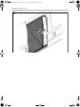
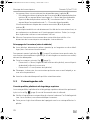
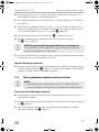
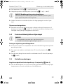
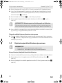
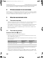
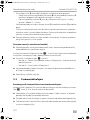
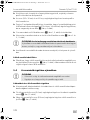
➤ Secure the deflection screw M4 (fig. 5 1, page 5) to the skirting board.
➤ Fit the guide cables into the bottom and top deflection screw (fig. 5 2 and 3,
page 5).
FT200-IOM-EMEA16.book Seite 11 Dienstag, 7. Januar 2020 11:31 11

EN
Installing the flyscreen Dometic FlyTec FT200
12
A
➤ Have two people carefully lift the pre-assembled flyscreen and position it in the
vehicle.
Adjusting the top guide rail
➤ Check whether the contour and position of the upper guide rail fit the vehicle
(see enlarged inset in fig. 7, page 5). You may need to adjust the upper guide
rail by cutting the two upper legs.
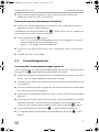
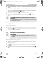
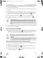
5.4 Securing the flyscreen in the vehicle
A
Securing the skirting board and upper guide rail
➤ Align the position of the cassette profile perpendicular to the skirting board and
the upper guide rail.
➤ Secure the skirting board to the bottom plate (fig. 6, page 5) with five counter-
sunk screws (Ø 4 mm).
➤ Secure the upper guide rail to the vehicle (fig. 7, page 5) with four countersunk
screws (Ø 4 mm).
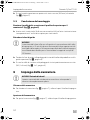
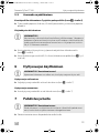
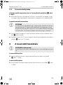
5.5 Completing installation
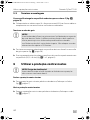
Riveting the cassette profile with the cover profile for the C pillar (fig. 8,
page 6)
➤ Put all the blind rivets (4 x 8 mm with stainless steel mandrel) through the drill
holes and rivet the components using a hand riveter.
NOTICE! Risk of breaking the lower plastic slider
Be careful when you are lifting and positioning the flyscreen and do not
bend or tilt the skirting board.
NOTICE!
•
Choose suitable screws depending on the floor and roof
construction.
•
Make sure that you do not drill through the floor and roof.
FT200-IOM-EMEA16.book Seite 12 Dienstag, 7. Januar 2020 11:31 11

EN
Dometic FlyTec FT200 Using the flyscreen
13
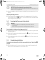
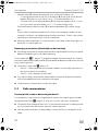
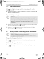
Tensioning the guide cables
A
➤ Tension the guide cables on the deflection screws on the skirting board and the
top guide rail (fig. 9, page 6).
➤ Secure the safety clips onto the deflection screws each with a screw
(M2.5 x 6 mm) (fig. 9 1 and 2, page 6).
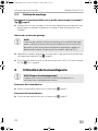
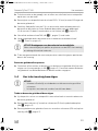
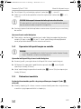
6 Using the flyscreen
A
Closing the flyscreen
➤ Pull the handle strip on the flyscreen to close the flyscreen (fig. 0, page 7).
Opening the flyscreen
➤ Pull the handle strip on the flyscreen to open the flyscreen (fig. 0, page 7).
7 Cleaning and maintenance
A
➤ Occasionally clean the product with a damp cloth.
➤ Spray the guide rails on the sliding surfaces periodically with small amounts of
silicone spray to achieve the easiest possible sliding of the cassette profile in the
guide rails.
NOTICE!
The tension of the cables affects the guidance and smooth running of the
handle strip. By changing the tension of the upper and lower cable, you
can adjust the parallel orientation of the handle strip to the right door
edge. Do not tension the cables more than 25 Newton.
NOTICE! Beware of damage!
The sliding door of the vehicle may be closed only when the flyscreen is
fully open.
NOTICE! Damage hazard
Do not use sharp or hard objects or cleaning agents for cleaning as these
may damage the product.
FT200-IOM-EMEA16.book Seite 13 Dienstag, 7. Januar 2020 11:31 11

EN
Warranty Dometic FlyTec FT200
14
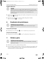
8Warranty
The statutory warranty period applies. If the product is defective, please contact the
service partner in your country (see back page).
Our experts will be happy to help you and will discuss the warranty process with you
in more detail.
9Disposal
➤ Place the packaging material in the appropriate recycling waste bins wherever
possible.
M
If you wish to finally dispose of the product, ask your local recycling centre
or specialist dealer for details about how to do this in accordance with the
applicable disposal regulations.
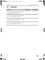
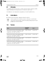
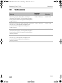
10 Versions
Version Dimensions Ref. no.
Version in direction of travel on the right for Fiat
Ducato, Citroën Jumper, Peugeot Boxer from model
year 2006, higher version
1298 x 1765 mm 9104117297
Version in direction of travel on the left for Fiat
Ducato, Citroën Jumper, Peugeot Boxer from model
year 2006, higher version
1298 x 1765 mm 9104117296
Version in direction of travel on the right for Fiat
Ducato, Citroën Jumper, Peugeot Boxer from model
year 2006, lower version
1128 x 1492 mm 9104117387
Version in direction of travel on the left for Fiat
Ducato, Citroën Jumper, Peugeot Boxer from model
year 2006, lower version
1128 x 1492 mm 9104117388
FT200-IOM-EMEA16.book Seite 14 Dienstag, 7. Januar 2020 11:31 11

DE
Dometic FlyTec FT200 Erklärung der Symbole
15
Bitte lesen Sie diese Anleitung vor der Inbetriebnahme sorgfältig durch
und bewahren Sie sie auf. Geben Sie sie im Falle einer Weitergabe des
Produktes an den Nutzer weiter.
Inhalt
1 Erklärung der Symbole . . . . . . . . . . . . . . . . . . . . . . . . . . . . . . . . . . . . . . . . . .15
2 Sicherheitshinweise . . . . . . . . . . . . . . . . . . . . . . . . . . . . . . . . . . . . . . . . . . . .15
3 Lieferumfang . . . . . . . . . . . . . . . . . . . . . . . . . . . . . . . . . . . . . . . . . . . . . . . . . .16
4 Bestimmungsgemäßer Gebrauch . . . . . . . . . . . . . . . . . . . . . . . . . . . . . . . . .16
5 Insektenschutz montieren. . . . . . . . . . . . . . . . . . . . . . . . . . . . . . . . . . . . . . . .17
6 Insektenschutz benutzen . . . . . . . . . . . . . . . . . . . . . . . . . . . . . . . . . . . . . . . 20
7 Reinigung und Pflege . . . . . . . . . . . . . . . . . . . . . . . . . . . . . . . . . . . . . . . . . . .21
8 Gewährleistung. . . . . . . . . . . . . . . . . . . . . . . . . . . . . . . . . . . . . . . . . . . . . . . .21
9 Entsorgung . . . . . . . . . . . . . . . . . . . . . . . . . . . . . . . . . . . . . . . . . . . . . . . . . . .21
10 Versionen. . . . . . . . . . . . . . . . . . . . . . . . . . . . . . . . . . . . . . . . . . . . . . . . . . . . 22
1 Erklärung der Symbole
A
I
2 Sicherheitshinweise
Beachten Sie die vom Fahrzeughersteller und vom Kfz-Handwerk vorgeschriebenen
Sicherheitshinweise und Auflagen!
Der Hersteller übernimmt in folgenden Fällen keine Haftung für Schäden:
•
Montage- oder Anschlussfehler
ACHTUNG!
Hinweis auf eine Situation, die zu Sachschäden führen kann, wenn sie
nicht vermieden wird.
HINWEIS
Ergänzende Informationen zur Bedienung des Produktes.
FT200-IOM-EMEA16.book Seite 15 Dienstag, 7. Januar 2020 11:31 11

DE
Lieferumfang Dometic FlyTec FT200
16
•
Beschädigungen am Produkt durch mechanische Einflüsse
•
Veränderungen am Produkt ohne ausdrückliche Genehmigung vom Hersteller
•
Verwendung für andere als die in der Anleitung beschriebenen Zwecke
A
ACHTUNG!
•
Wenn Sie nicht über ausreichende technische Kenntnisse zum Ein-
bauen von Komponenten in Fahrzeugen verfügen, sollten Sie sich den
Insektenschutz von einem Fachmann ins Fahrzeug einbauen lassen.
•
Prüfen Sie, ob die Abmessungen des Insektenschutzes zu Ihrem
Fahrzeug passen.
•
Die Montage des Insektenschutzes erfordert zwei Personen.
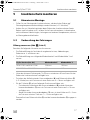
3 Lieferumfang
Die Schrauben für die fahrzeugseitige Befestigung sind nicht im Lieferumfang
enthalten.
4 Bestimmungsgemäßer Gebrauch
Dometic FlyTec FT200 ist ein horizontal verschiebbarer, faltbarer Insektenschutz für
Schiebetüren von Campingbussen. Verfügbare Versionen siehe Tabelle, Seite 22.
Pos. in
Abb. 1, Seite 3
Anzahl Beschreibung
1 1 Trittleiste
2 1 Kassettenprofil mit Fliegengaze und Führungsseilen
3 1 Abdeckprofil C-Säule
4 7 Blindniete (4 x 8 mm mit VA-Dorn)
5 1 Befestigungsschraube M5 x 30 mm und Mutter M5
6 1 Führungsschiene oben
7 1 Sicherungsbügel und Schraube M2,5 x 6
8 1 Umlenkschraube M4 mit Sicherungsbügel und
Schraube M2,5 x 6
– Montage- und Bedienungsanleitung
FT200-IOM-EMEA16.book Seite 16 Dienstag, 7. Januar 2020 11:31 11

DE
Dometic FlyTec FT200 Insektenschutz montieren
17
5 Insektenschutz montieren
5.1 Hinweise zur Montage
•
Prüfen Sie vor Montage des Insektenschutzes, ob durch den Einbau ggf.
Fahrzeugkomponenten beschädigt werden könnten (z. B. Schränke).
•
Achten Sie aus Sicherheitsgründen beim Einbau des Insektenschutzes (beim
Bohren und Schrauben usw.) auf den Verlauf von vorhandenen, insbesondere
nicht sichtbaren Kabelsträngen, Leitungen und anderen Komponenten, die sich
im Montagebereich befinden.
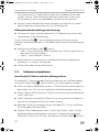
5.2 Vorbereitung des Fahrzeuges
Öffnung ausmessen (Abb. 2, Seite 3)
Beachten Sie folgende Hinweise zum Ausmessen:
•
Die Einbauöffnung darf nicht durch angebaute Leisten, Abdeckungen,
Einbauten o. ä. verkleinert sein.
•
Die Einbauöffnung muss folgende Mindestbreite X und Mindesthöhe Y auf-
weisen:
•
Hinter der hinteren Dichtung der Tür (1) muss mindestens 40 mm Raum für den
Einbau des Insektenschutzes verfügbar sein.
•
Zwischen der Außenkante des Karosseriebodens (4) und Einbauschränken (2)
(z. B. Küche) muss ein Freiraum mit einer Breite von A = 18 mm verfügbar sein.
•
Für die Trittleiste (5) müssen folgende Freiräume verfügbar sein:
– Zwischen der Außenkante des Karosseriebodens (4) und der Kante des
Innenausbaubodens (3) muss ein Freiraum mit einer Breite von A = 18 mm
verfügbar sein.
– Ab der Kante des Innenausbaubodens (3) muss in einer Höhe von B = 3 mm
ein Freiraum mit einer Tiefe von C = 15 mm verfügbar sein.
Eventuell müssen Einbauschränke (2) und der Innenausbauboden (3) angepasst
werden.
FlyTec-Version (Art.-Nr.) Mindestbreite X Mindesthöhe Y
9104117297 und 9104117296 1298 mm 1765 mm
9104117387 und 9104117388 1128 mm 1492 mm
FT200-IOM-EMEA16.book Seite 17 Dienstag, 7. Januar 2020 11:31 11

DE
Insektenschutz montieren Dometic FlyTec FT200
18
•
Der Insektenschutz muss oben direkt mit dem Karosserieblech verschraubt
werden, nicht nur an der Verkleidung oder dem Innenausbau. Unten ist die
Verschraubung in den Innenausbauboden normalerweise ausreichend.
➤ Messen Sie die Einbauöffnung in Ihrem Fahrzeug aus und prüfen Sie, ob die
Abmessungen des Insektenschutzes an Ihr Fahrzeug passen.
Öffnung beschneiden (abhängig vom Fahrzeug)
➤ Demontieren Sie ggf. störende Anbauteile (z. B. Bodenabschlussleisten oder
Verkleidungen) in der Einbauöffnung.
Um die Trittleiste (Abb. 1 1, Seite 3) bündig montieren zu können, müssen
eventuell vorhandene Einbauten (z. B. die Böden oder Einbauschränke) beschnitten
werden.
➤ Zeichnen Sie wie folgt an (Abb. 2, Seite 3):
– Maß A = 18 mm (Breite des unteren Schenkels der Trittleiste), gemessen von
der Kante des Karosserieblechs
– Maß B = 3 mm (Höhe der Trittleiste).
➤ Beschneiden Sie, falls erforderlich, vorhandene Einbauten mit geeignetem
Werkzeug, z. B. mit einer Schwingsäge.
➤ Glätten und säubern Sie die Schnittkanten.
5.3 Schienen vormontieren
Kassettenprofil, Trittleiste und obere Führungsschiene
Kassettenprofil, Trittleiste und obere Führungsschiene müssen am Boden liegend
vormontiert werden (Abb. 3, Seite 4), bevor sie im Fahrzeug platziert werden.
➤ Prüfen Sie, ob das Abdeckprofil zwischen C-Säule und Innenausbau eingescho-
ben werden kann. Ggf. müssen Sie die Kontur durch Beschneiden anpassen.
➤ Führen Sie den unteren Gleiter der Griffleiste zusammen mit dem Kassettenprofil
in die Trittleiste ein.
➤ Ziehen Sie die Kassette und die Griffleiste etwas auseinander und schieben Sie
dann das Kassettenprofil auf die Nase an der Trittleiste.
➤ Befestigen Sie das Kassettenprofil mit der Schraube (M5 x 30 mm) und Mutter
M5 an der obere Führungsschiene.
➤ Stecken Sie das Abdeckprofil für die C-Säule in die Kassette, so dass sich die
Bohrlöcher übereinander befinden und fixieren Sie beiden Bauteile mit drei
Blindnieten (4 x 8 mm mit VA-Dorn), ohne diese zu vernieten (Abb. 4, Seite 4).
FT200-IOM-EMEA16.book Seite 18 Dienstag, 7. Januar 2020 11:31 11

DE
Dometic FlyTec FT200 Insektenschutz montieren
19
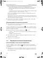
➤ Schrauben Sie die Umlenkschraube M4 (Abb. 5 1., Seite 5) in die Trittleiste.
➤ Hängen Sie die Führungsseile in die untere und in die obere Umlenkschraube ein
(Abb. 5 2. und 3., Seite 5).
A
➤ Heben Sie den vormontierten Insektenschutz zu zweit vorsichtig auf und
positionieren Sie ihn im Fahrzeug.
Obere Führungsschiene anpassen
➤ Prüfen Sie, ob die Kontur und die Lage der oberen Führungsschiene zum
Fahrzeug passt (siehe Lupe in Abb. 7, Seite 5). Ggf. müssen Sie die obere
Führungsschiene durch Beschneiden der beiden oberen Schenkel anpassen.
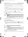
5.4 Insektenschutz im Fahrzeug befestigen
A
Trittleiste und obere Führungsschiene befestigen
➤ Richten Sie die Lage des Kassettenprofils rechtwinklig zur Trittleiste und zur
oberen Führungsschiene aus.
➤ Befestigen Sie die Trittleiste mit fünf Senkkopfschrauben (Ø4 mm) auf der
Bodenplatte (Abb. 6, Seite 5).
➤ Befestigen Sie die obere Führungsschiene mit vier Senkkopfschrauben (Ø4 mm)
am Fahrzeug (Abb. 7, Seite 5).
5.5 Montage abschließen
Kassettenprofil mit dem Abdeckprofil für die C-Säule vernieten (Abb. 8,
Seite 6)
➤ Stecken Sie alle Blindniete (4 x 8 mm mit VA-Dorn) durch die Bohrlöcher und ver-
nieten Sie die Bauteile mit Hilfe einer Blindnietzange miteinander.
ACHTUNG! Bruchgefahr des unteren Kunststoffgleiters
Seien Sie beim Anheben und Positionieren des Insektenschutzes im
Fahrzeug vorsichtig und biegen oder verkanten Sie die Trittleiste nicht.
ACHTUNG!
•
Wählen Sie abhängig von der Boden- und Dachkonstruktion
geeignete Schrauben aus.
•
Achten Sie darauf, dass Sie Boden und Dach nicht durchbohren.
FT200-IOM-EMEA16.book Seite 19 Dienstag, 7. Januar 2020 11:31 11

DE
Insektenschutz benutzen Dometic FlyTec FT200
20
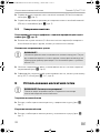
Führungsseile nachspannen
A
➤ Spannen Sie die Führungsseile an den Umlenkschrauben an der Trittleiste und an
der oberen Führungsschiene (Abb. 9, Seite 6) nach.
➤ Fixieren Sie die Sicherungsbügel auf den Umlenkschrauben jeweils mit einer
Schraube (M2,5 x 6 mm) (Abb. 9 1 und 2, Seite 6).
6 Insektenschutz benutzen
A
Insektenschutz schließen
➤ Ziehen Sie den Insektenschutz an der Griffleiste zu, um den Insektenschutz zu
schließen (Abb. 0, Seite 7).
Insektenschutz öffnen
➤ Ziehen Sie den Insektenschutz an der Griffleiste auf, um den Insektenschutz zu
öffnen (Abb. 0, Seite 7).
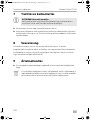
ACHTUNG!
Die Spannung der Seile beeinflusst die Führung und Leichtgängigkeit
der Griffleiste. Durch unterschiedliche Spannung der oberen und unte-
ren Seil kann die parallele Ausrichtung der Griffleiste zur rechten Tür-
kante justiert werden. Spannen Sie das Seilpaar nicht mehr als 25 N.
ACHTUNG! Beschädigungsgefahr!
Die Schiebetür des Fahrzeugs darf nur bei vollständig geöffnetem
Insektenschutz geschlossen werden.
FT200-IOM-EMEA16.book Seite 20 Dienstag, 7. Januar 2020 11:31 11
A página está carregando ...
A página está carregando ...
A página está carregando ...
A página está carregando ...
A página está carregando ...
A página está carregando ...
A página está carregando ...
A página está carregando ...
A página está carregando ...
A página está carregando ...
A página está carregando ...
A página está carregando ...
A página está carregando ...
A página está carregando ...
A página está carregando ...
A página está carregando ...
A página está carregando ...
A página está carregando ...
A página está carregando ...
A página está carregando ...
A página está carregando ...
A página está carregando ...
A página está carregando ...
A página está carregando ...
A página está carregando ...
A página está carregando ...
A página está carregando ...
A página está carregando ...
A página está carregando ...
A página está carregando ...
A página está carregando ...
A página está carregando ...
A página está carregando ...
A página está carregando ...
A página está carregando ...
A página está carregando ...
A página está carregando ...
A página está carregando ...
A página está carregando ...
A página está carregando ...
A página está carregando ...
A página está carregando ...
A página está carregando ...
A página está carregando ...
A página está carregando ...
A página está carregando ...
A página está carregando ...
A página está carregando ...
A página está carregando ...
A página está carregando ...
A página está carregando ...
A página está carregando ...
A página está carregando ...
A página está carregando ...
A página está carregando ...
A página está carregando ...
A página está carregando ...
A página está carregando ...
A página está carregando ...
A página está carregando ...
A página está carregando ...
A página está carregando ...
A página está carregando ...
A página está carregando ...
A página está carregando ...
A página está carregando ...
A página está carregando ...
A página está carregando ...
A página está carregando ...
A página está carregando ...
A página está carregando ...
A página está carregando ...
A página está carregando ...
A página está carregando ...
A página está carregando ...
A página está carregando ...
A página está carregando ...
A página está carregando ...
A página está carregando ...
A página está carregando ...
A página está carregando ...
A página está carregando ...
A página está carregando ...
A página está carregando ...
A página está carregando ...
A página está carregando ...
A página está carregando ...
A página está carregando ...
A página está carregando ...
A página está carregando ...
A página está carregando ...
A página está carregando ...
A página está carregando ...
A página está carregando ...
A página está carregando ...
A página está carregando ...
A página está carregando ...
A página está carregando ...
A página está carregando ...
A página está carregando ...
A página está carregando ...
A página está carregando ...
A página está carregando ...
A página está carregando ...
A página está carregando ...
A página está carregando ...
A página está carregando ...
A página está carregando ...
A página está carregando ...
A página está carregando ...
A página está carregando ...
A página está carregando ...
-
 1
1
-
 2
2
-
 3
3
-
 4
4
-
 5
5
-
 6
6
-
 7
7
-
 8
8
-
 9
9
-
 10
10
-
 11
11
-
 12
12
-
 13
13
-
 14
14
-
 15
15
-
 16
16
-
 17
17
-
 18
18
-
 19
19
-
 20
20
-
 21
21
-
 22
22
-
 23
23
-
 24
24
-
 25
25
-
 26
26
-
 27
27
-
 28
28
-
 29
29
-
 30
30
-
 31
31
-
 32
32
-
 33
33
-
 34
34
-
 35
35
-
 36
36
-
 37
37
-
 38
38
-
 39
39
-
 40
40
-
 41
41
-
 42
42
-
 43
43
-
 44
44
-
 45
45
-
 46
46
-
 47
47
-
 48
48
-
 49
49
-
 50
50
-
 51
51
-
 52
52
-
 53
53
-
 54
54
-
 55
55
-
 56
56
-
 57
57
-
 58
58
-
 59
59
-
 60
60
-
 61
61
-
 62
62
-
 63
63
-
 64
64
-
 65
65
-
 66
66
-
 67
67
-
 68
68
-
 69
69
-
 70
70
-
 71
71
-
 72
72
-
 73
73
-
 74
74
-
 75
75
-
 76
76
-
 77
77
-
 78
78
-
 79
79
-
 80
80
-
 81
81
-
 82
82
-
 83
83
-
 84
84
-
 85
85
-
 86
86
-
 87
87
-
 88
88
-
 89
89
-
 90
90
-
 91
91
-
 92
92
-
 93
93
-
 94
94
-
 95
95
-
 96
96
-
 97
97
-
 98
98
-
 99
99
-
 100
100
-
 101
101
-
 102
102
-
 103
103
-
 104
104
-
 105
105
-
 106
106
-
 107
107
-
 108
108
-
 109
109
-
 110
110
-
 111
111
-
 112
112
-
 113
113
-
 114
114
-
 115
115
-
 116
116
-
 117
117
-
 118
118
-
 119
119
-
 120
120
-
 121
121
-
 122
122
-
 123
123
-
 124
124
-
 125
125
-
 126
126
-
 127
127
-
 128
128
-
 129
129
-
 130
130
-
 131
131
-
 132
132


Dometic FlyTec FT200 Instruções de operação
- Tipo
- Instruções de operação
em outros idiomas
- français: Dometic FlyTec FT200 Mode d'emploi
- italiano: Dometic FlyTec FT200 Istruzioni per l'uso
- slovenčina: Dometic FlyTec FT200 Návod na používanie
- dansk: Dometic FlyTec FT200 Betjeningsvejledning
Artigos relacionados
-
Dometic FlyTec FT100 Instruções de operação
-
-
-
Dometic CL440LDC, CL440LGC, CL460LDC, CL460LGC Instruções de operação
-
Dometic PLB40 Instruções de operação
-
-
-
-
Dometic PerfectRoof PR4500 Guia de instalação
-