Grundfos AQC-D6 Installation And Operating Instructions Manual
- Tipo
- Installation And Operating Instructions Manual

AQC-D6
ClO
2
measuring cell / measuring module
Installation and operating instructions
GRUNDFOS INSTRUCTIONS

2

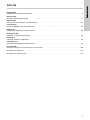
Table of contents
3
AQC-D6
English (GB)
Installation and operating instructions . . . . . . . . . . . . . . . . . . . . . . . . . . . . . . . . . . . . . . . . . . . . . . . . . . . . . . . . . . . 4
Deutsch (DE)
Montage- und Betriebsanleitung . . . . . . . . . . . . . . . . . . . . . . . . . . . . . . . . . . . . . . . . . . . . . . . . . . . . . . . . . . . . . . 17
Español (ES)
Instrucciones de instalación y funcionamiento. . . . . . . . . . . . . . . . . . . . . . . . . . . . . . . . . . . . . . . . . . . . . . . . . . . . 30
Français (FR)
Notice d'installation et de fonctionnement . . . . . . . . . . . . . . . . . . . . . . . . . . . . . . . . . . . . . . . . . . . . . . . . . . . . . . . 43
Italiano (IT)
Istruzioni di installazione e funzionamento. . . . . . . . . . . . . . . . . . . . . . . . . . . . . . . . . . . . . . . . . . . . . . . . . . . . . . . 56
Nederlands (NL)
Installatie- en bedieningsinstructies . . . . . . . . . . . . . . . . . . . . . . . . . . . . . . . . . . . . . . . . . . . . . . . . . . . . . . . . . . . . 69
Polski (PL)
Instrukcja montażu i eksploatacji . . . . . . . . . . . . . . . . . . . . . . . . . . . . . . . . . . . . . . . . . . . . . . . . . . . . . . . . . . . . . . 82
Português (PT)
Instruções de instalação e funcionamento. . . . . . . . . . . . . . . . . . . . . . . . . . . . . . . . . . . . . . . . . . . . . . . . . . . . . . . 95
Русский (RU)
Паспорт, Руководство по монтажу и эксплуатации . . . . . . . . . . . . . . . . . . . . . . . . . . . . . . . . . . . . . . . . . . . . . 108
Declaration of conformity . . . . . . . . . . . . . . . . . . . . . . . . . . . . . . . . . . . . . . . . . . . . . . . . . . . . . . . . . . . . . . . . . . . 122
Declaration of conformity RU . . . . . . . . . . . . . . . . . . . . . . . . . . . . . . . . . . . . . . . . . . . . . . . . . . . . . . . . . . . . . . . . 123

English (GB)
4
English (GB) Installation and operating instructions
Original installation and operating instructions
CONTENTS
Page
1. Symbols used in this document
1. Symbols used in this document
4
2. Device description
5
3. General information
5
4. Applications
5
5. Safety
5
5.1 Obligations of the owner/operations manager
5
5.2 Avoidance of danger
5
6. Technical data
6
6.1 General data on the AQC-D6
6
6.2 General data on the measuring module
6
6.3 Dimensional sketch / drilling diagram
7
7. Function
8
7.1 Description of the AQC-D6
8
7.2 Design of the measuring cell
8
7.3 Function of the AQC-D6
8
7.4 Design of the measuring module
9
7.5 Functional principle of measurement module
9
8. Installation
10
8.1 Transport and storage
10
8.2 Unpacking
10
8.3 Installation requirements
10
8.4 Installation
10
9. Commissioning
10
9.1 Water connections
10
9.2 Electrical connections
11
9.3 Preparing the measuring system
12
9.4 Starting up the measuring system
13
9.5 Starting up the measuring module
13
9.6 Basic settings
13
9.7 Calibration
14
10. Operation
14
10.1 Switching on
14
10.2 Operation
14
10.3 Interruptions
14
11. Fault finding
15
12. Maintenance
16
12.1 Functional check
16
12.2 Cleaning
16
13. Spare parts
16
14. Disposal
16
Warning
These complete installation and operating
instructions are also available on www.grundfos.com.
Prior to installation, read these installation and
operating instructions. Installation and operation
must comply with local regulations and accepted
codes of good practice.
Warning
If these safety instructions are not observed, it may
result in personal injury.
Caution
If these safety instructions are not observed, it may
result in malfunction or damage to the equipment.
Note
Notes or instructions that make the job easier and
ensure safe operation.

English (GB)
5
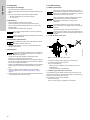
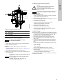
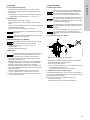
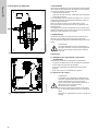
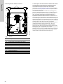
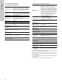
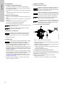
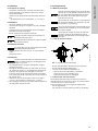
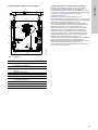
2. Device description
Fig. 1 AQC-D6 measuring cell
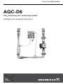
Fig. 2 Measuring module
3. General information
These installation and operating instructions contain all
information important for users of the AquaCell AQC-D6
measuring cells and the measuring module:
• technical data
• instructions for commissioning, use and maintenance
• safety information.
Should you require further information or should you encounter
problems that are not handled in sufficient depth in this manual,
please contact Grundfos.
We shall be pleased to support you with our comprehensive
know-how in the fields of measurement and control as well as
water treatment.
We always welcome suggestions on how to optimise our
installation and operating instructions to satisfy our customers.
4. Applications
The AQC-D6 measuring cells are used for measuring the
concentration of chlorine dioxide in water within the scope of the
potential applications described in this manual.
5. Safety
5.1 Obligations of the owner/operations manager
The owner/operations manager is responsible for:
• compliance with country-specific safety regulations
• training of operating personnel
• provision of prescribed protective gear
• implementation of regular maintenance.
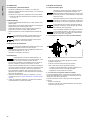
5.2 Avoidance of danger
TM03 7147 0813TM03 7148 0813
Warning
Other applications are not approved and not
permitted. Grundfos cannot be held liable for any
damage resulting from incorrect use.
Warning
Installation and connection of the device and the
associated supplementary component must only be
carried out by authorised personnel.
Switch off the power supply before connecting the
power supply cable and relay contacts!
Do not dismantle the device!
Cleaning, maintenance and repairs must only be
carried out by authorised personnel!
The local safety regulations must be observed!

English (GB)
6
6. Technical data
6.1 General data on the AQC-D6
6.2 General data on the measuring module
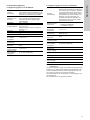
6.2.1 Electrical data of the UPS 25-60N circulating pump
6.2.2 Factory settings of the measuring module as supplied
The bypass measuring module is fitted on the wall mounting plate
and tested for leaks. The fixing accessories supplied allow the
wall mounting plate to be attached to a solid brick or concrete
wall.
The connection cable of the circulating pump is not included in
the scope of delivery.
The circulating pump is preset to level 3.
Design
(measuring cells)
95708118 (314-181): Chlorine dioxide
measuring cell, consisting of a 95708117
(314-180) sensor, flow fitting and water
sensor, mounted on a plate
Housing material
PEEK, PVDF, acrylic, stainless steel and
silicone rubber, resistant to surfactants
and similar water additives
Measuring range 0.00 - 2.00 mg/l
Cross-sensitivity
Cross-sensitivity if chlorine is present:
approximately 2 %
Cross-sensitivity if chlorite is present:
<1%
Resolution 0.01 mg/l
Response time T
90
~ 30 seconds
Temperature drift
Temperature-compensated measuring
signal
Permissible
process water
temperature
+5 to +70 °C
Sample water flow
rate
Minimum 30 l/h
Maximum permitted
pressure
8 bar
Permissible
ambient
temperature
+5 to +35 °C
Maximum permitted
relative humidity
80 %, no condensation
Design
(measuring module)
95708029 (550-2000-1):
Measuring module, consisting of a
95708117 (314-180) sensor, flow fitting
and water sensor, sample water bypass
with feed and outlet line for the flow
fitting, spring-loaded taper seat check
valve, circulating pump for compensation
of any pressure drops that occur, as well
as stop valves at the input and output,
mounted on a plate
Material of the
measuring module
• Pipework: PP, PP/brass
• Gaskets: FPM/PTFE
• Circulating pump: bronze
Permissible process
water temperature
+5 to +70 °C
Sample water flow
rate
At least 30 l/h
Maximum permitted
pressure
8 bar
Permissible ambient
temperature
+5 to +35 °C
Maximum permitted
relative humidity
80 %, no condensation
Weight 15 kg
Measuring module
input / output
Connection for DN 20 pipe in PP or PVC
Supply voltage 230 V, single-phase
Frequency 50/60/70 Hz
Maximum power
consumption
50 W / 60 W / 70 W
Enclosure class IP44

English (GB)
7
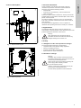
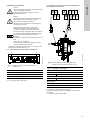
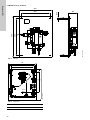
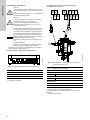
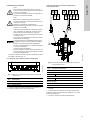
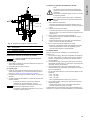
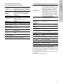
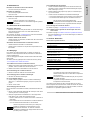
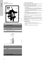
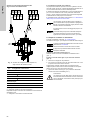
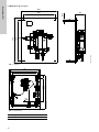
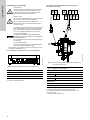
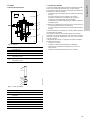
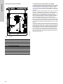
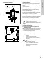
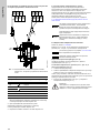
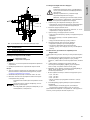
6.3 Dimensional sketch / drilling diagram
Fig. 3 AQC-D6
Fig. 4 Measuring module
All dimensions in mm.
TM03 7149 0813
300
260
360
395
68
Ø 10
TM03 7150 0813
Height Width Depth
650 550 180
550
500
450
ø 10.5
DN20
DN20
65
430
650

English (GB)
8
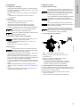
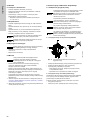
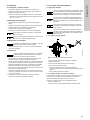
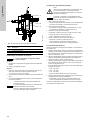
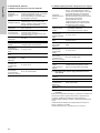
7. Function
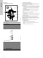
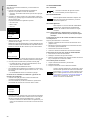
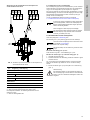
7.1 Description of the AQC-D6
Fig. 5 AQC-D6
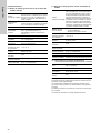
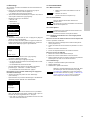
7.2 Design of the measuring cell
Fig. 6 Measuring cell
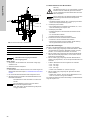
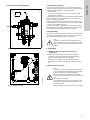
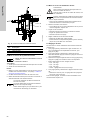
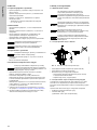
7.3 Function of the AQC-D6
The AQC-D6 measuring cell is used to determine the chlorine
dioxide concentration in potable water.
Sample water is taken at a representative position and fed to the
measuring cell.
• The sample water flow rate can be adjusted on the flow fitting.
• A water sensor can, for example, be used to trigger an alarm
or to switch off the control functions if there is insufficient
sample water.
• The substance to be determined (ClO
2
) is measured on the
noble-metal electrode.
The material to be determined (ClO
2
) generates an electric
current:
• The electric current is in the µA range.
• The electric current is proportional to the concentration of the
ClO
2
parameter.
The measuring cell is controlled with a potentiostat integrated in
the measuring amplifier.
A precisely defined potential of the measuring electrode is
retained through a reference system. This results in a linear
response for the measuring cell as well as a stable zero point for
the measurement.
The measuring amplifier and regulator of the Oxiperm Pro
chlorine dioxide system:
• amplifies the current
• calculates it using the calibration parameters
• displays the chlorine dioxide concentration as a numerical
value
• controls a dosing pump as an actuator.
TM03 7151 0813
Pos. Description
1 Base plate
2 Flow fitting
3 Measuring cell
4 Connection for sample water outlet, hose 6/8 mm
5 Connection for sample water inlet, hose 6/8 mm
TM03 7152 0813
Pos. Description
1 Four-pole connection bush
2 Electrode adapter with integrated electronics
3 Reference electrode
4 Measuring electrode
5 O-ring 14 x 1.8 mm
6 Electrolyte chamber
7 Measurement opening
8Protection cap
1
2
3
5
4
1
2
3
4
5
6
6
7
8

English (GB)
9
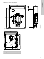
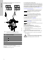
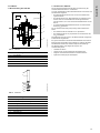
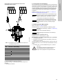
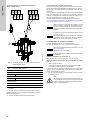
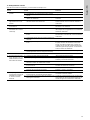
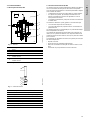
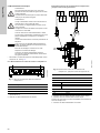
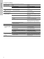
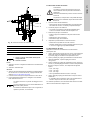
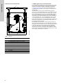
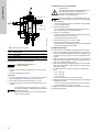
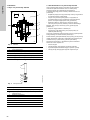
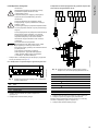
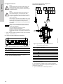
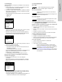
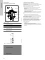
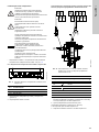
7.4 Design of the measuring module
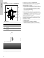
Fig. 7 AQC-D6
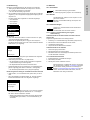
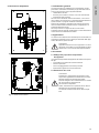
7.5 Functional principle of measurement module
The measuring module is used to feed sample water to the
AQC-D6 measuring cell for determining the chlorine dioxide
concentration in potable water. Please refer to section
7.3 Function of the AQC-D6. Here the sample water is taken from
the main water line using a bypass and then fed back.
The sample water is taken from the main water line (pos. 2)
using a extraction fitting (pos. 1), from where it flows through the
bypass and a feed fitting (pos. 7) back into the main water line
(pos. 2). The spring-loaded taper seat check valve (pos. 5)
prevents the sample water from flowing back. The stream of
sample water can be blocked off using the isolating valves
(pos. 10). The circulating pump (pos. 4) drives the stream of
sample water through the bypass. It is designed specifically for
compensating the internal pressure drops. The extraction and
feed line must therefore be kept as short as possible.
Sample water is then taken from this bypass via the sample water
extraction (pos. 6), from where it flows through the flow fitting
(pos. 3) to the measuring cell and is then fed back to the bypass
through the sample water recirculation fitting (pos. 8). To do this,
the throttle valve (pos. 9) restricts the flow of water in the bypass
until enough sample water flows through the sample water
extraction section (pos. 6) to the flow fitting / AQC-D6 (pos. 3)
measuring cell.
TM03 7153 0813
Pos. Description
1 Extraction fitting (supplied by the customer)
2 Main water line (supplied by the customer)
3 Flow fitting / AQC-D6 measuring cell
4 Circulating pump
5 Taper seat check valve
6 Sample water removal
7 Feed fitting (supplied by the customer)
8 Sample water recirculation
9 Throttle valve
10 Isolating valves
1
2
7
3
4
5
6
8
10
10
9
ø 10.5

English (GB)
10
8. Installation
8.1 Transport and storage
• Transport the device carefully, do not drop!
• Store the electrodes with electrolyte filling and protection cap
fitted.
• Store at a dry location, protected from direct sunlight.
– Storage temperature for measuring modules:
-5 °C to +50 °C.
8.2 Unpacking
• When unpacking, be aware of loose parts.
• Check the delivery to ensure that no parts are missing.
• Also check for transport damage. Never fit or connect any
damaged parts.
• Install as soon as possible after unpacking.
8.3 Installation requirements
• Ambient temperature of +5 to 35 °C at the installation site.
• Vibration-free location.
8.4 Installation
• The fixing accessories supplied include hanger bolts,
dowel pins, compression springs and nuts.
• Attach the AQC-D6 measuring cell or the measuring module to
a stone or concrete wall using the fixing accessories supplied.
Do not twist or distort the devices.
• Nuts may be attached behind the base plate to ensure that the
module is free from distortion when attached to an uneven
wall.
1. Mark the location of the boreholes, and then drill them
(∅10 mm). See section 6.3 Dimensional sketch / drilling
diagram.
2. Insert the dowel pins, and screw the AQC-D6 measuring cell
or the measuring module onto the wall.
9. Commissioning
9.1 Water connections
9.1.1 AQC-D6 water connections
Fig. 8 AQC-D6 with open water outlet
• Connect the sample water supply line (hose 6/8 mm).
• Connect the sample water drain line.
• Do one of the following:
– When a drain is available, connect (hose 6/8 mm) to a
suitable drain.
– Feed the fluid back to the pipework.
9.1.2 Measuring module water connections
The standard scope of delivery includes one PP and one PVC
insertion section each for the input and output of the measuring
module for connecting a pipe in DN 20.
When installing, do one of the following:
• Weld on a PP pipe.
• Glue on a PVC pipe (only suitable for cold water).
Note
Do not allow foreign bodies to enter any parts that
carry water.
Note
Retain the packing material or dispose of it according
to local regulations.
Note
The measuring module should be fitted as close as
possible to the main water line.
Caution
Always fit the AQC-D6 measuring cell or measuring
module on a flat and stable surface. Do not twist or
distort the base plate.
Caution
Observe the maximum permissible pressures and
temperatures for materials used! The measuring cell
must never be exposed to shock pressure. It can be
operated up to a maximum of 8 bar.
Caution
When selecting the supply and discharge conduits,
please observe their resistance against the
temperature and pressure occurring in your
application.
Note
For the best possible accuracy of the measured
value, keep the flow of sample water as constant as
possible.
Note
To keep the system short and prevent drops in
pressure, the connection lines to the measuring cell
or the measuring module should be kept as short as
possible.
TM03 7154 0813

English (GB)
11
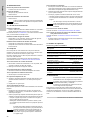
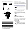
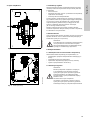
9.2 Electrical connections
• Connect the cable with four-pole screw-on connection to the
measuring cell. Please refer to fig. 10.
9.2.1 Connecting the measuring cell to Oxiperm Pro
Fig. 9 Cable connection block on the base of the
Oxiperm Pro
1. Connect the measuring cell to Oxiperm Pro (connection 1).
2. Connect the power supply cable.
Connecting to the connection block of the Oxiperm Pro
up to software version V0.19
Fig. 10 Connecting to the connection block of the
Oxiperm Pro, up to software version V0.19
1. Connect any current output cables as required.
2. Connect any relay contacts as required.
Always observe the Oxiperm Pro installation and operating
instructions.
3. Connect the power supply cable.
Warning
Incorrect electrical connections can result in serious
injury and damage to property!
Electrical connections may only be set up by
authorised personnel!
Warning
Switch off the power supply before connecting the
power supply cable and the relay contacts!
Observe the local safety regulations!
Protect the cable connections and plugs against
corrosion and moisture.
Caution
Before connecting the power supply cable,
check that the supply voltage specified on the
nameplate corresponds to the local conditions.
An incorrect supply voltage may destroy the device!
To guarantee electromagnetic compatibility (EMC),
the input and current output cables must be
screened.
Connect the screening to the screen ground on one
side.
Refer to the wiring diagram!
Route the input, current output and power supply
cables in separate cable channels
TM03 7155 0813
Pos. Description
1 Power supply
7 Measuring cell
13.2 Water sensor
1
7
13.2
TM03 7156 0813
Pos. Connection Description
AQC-D6 measuring cell
65 - 12 V Brown
66 White
67 M Yellow
70 Green
Water sensor
55 + Black
56 - White
55 57 67 69
56 58 68 70
71
72
65
66

English (GB)
12
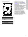
Connecting to the connection block of the Oxiperm Pro
from software version V0.20
Fig. 11 Connecting to the connection block of the
Oxiperm Pro, from software version V0.20
1. Connect any current output cables as required.
2. Connect any relay contacts as required.
Always observe the Oxiperm Pro installation and operating
instructions.
3. Connect the power supply cable.
9.2.2 Connecting the circulating pump
The circulating pump (asynchronous squirrel cage motor) on the
measuring module is powered directly by the power supply and is
not connected to the Oxiperm Pro control unit. It is equipped with
thermal overload or impedance protection, and therefore external
motor protection is not required. The required connected loads
are indicated on the nameplate of the circulating pump.
You will also find electrical data in section 6.2.1 Electrical data of
the UPS 25-60N circulating pump.
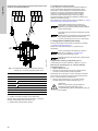
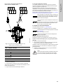
9.3 Preparing the measuring system
Please also observe section 10. Operation.
The measuring cell (pos. 3) is filled with electrolyte at delivery.
Prepare the flow fitting (pos. 2):
Loosen the stainless steel ring with 1" thread (pos. 1).
Fit the measuring cell (pos. 3) in the flow fitting (pos. 2).
1. Remove the protection cap.
2. Slide the measuring cell into the flow fitting until the liquid
flows well around it.
Tip: When fitted in its final position, the upper part of the
measuring cell should still project around 20 mm out of the flow
fitting.
3. Fix the measuring cell (pos. 3) in place using the stainless
steel ring (pos. 1).
TM04 0729 0813
Pos. Connection Description
AQC-D6 measuring cell
67 - 12 V Brown
68 White
69 M Yellow
72 Green
Water sensor
54 + Black
53 - White
53 55 57
54 56 58
67 69
68 70
71
72
Note
An on/off switch should be connected to the power
supply cable to allow the circulating pump to be
switched off during long measuring module
downtimes.
Caution
Dry running will damage the circulating pump!
The pump bearings are lubricated by the liquid
flowing through the pump, although the pressure
must be at least 0.05 bar (0.5 mWS).
Caution
Please observe the precise instructions in section
12.2 Cleaning!
Risk of incorrect measurement.
Note
The protection cap of the measuring cell is filled with
electrolyte!
Warning
A sudden failure of the measuring cell can lead to
excessive levels of chlorine dioxide! Make sure you
have suitable provisions in place for this!

English (GB)
13
Fig. 12 Flow fitting with measuring cell
9.4 Starting up the measuring system
First
1. Check that all electrical connections are connected properly.
2. Check the water connections.
Secondly
3. Start up the sample water supply. For versions with a
measuring module, please refer to section 9.5 Starting up the
measuring module.
4. The minimum sample water flow is around 30 l/h.
5. Switch on the power supply, or connect the electrode cable on
the measuring cell.
9.5 Starting up the measuring module
1. Open the isolating valve.
– Open all isolating valves between the measuring module
input/output and the main water line.
2. Switch on the circulating pump.
– The circulating pump is switched on separately, i.e. not via
the Oxiperm Pro control unit.
3. Deaerate the circulating pump.
– Unscrew the vent plug on the front of the motor.
– Deaerate for approximately 30 seconds.
– Screw the vent plug back in.
4. Set the flow rate through the flow fitting.
– Determine the flow rate in the flow fitting.
– Slowly close the throttle valve (turn the lever) until the
desired flow rate is reached.
9.6 Basic settings
Observe the Oxiperm Pro installation and operating instructions.
1. Use the [Up] and [Down] buttons on the measuring amplifier in
the "Setup" menu to select the "Measuring cell" line, and
press [OK] to access the corresponding menu.
2. Use the [Up] and [Down] buttons to select the desired
AQC-D6 measuring cell, and press [OK] to return to the
"Setup" menu.
3. Use the [Up] and [Down] buttons to select the "Measuring
ranges" line, and press [OK] to access the corresponding
menu.
• The following are available in the "Measuring ranges" menu:
– 0.00 - 0.50 mg/l
– 0.00 - 1.00 mg/l
– 0.00 - 2.00 mg/l
– Others: freely adjustable from 0.00 to 2.00 mg/l.
4. Use the [Up] and [Down] buttons to select the desired
measuring range.
– You can use the "Others" selection to freely set the
measuring range from 0.00 to 2.00 mg/l.
For further settings, please refer to the Oxiperm Pro installation
and operating instructions.
TM03 7157 0813
Pos. Description
1 Stainless steel ring
2 Flow fitting
3 Measuring cell
Note
1. Switch on the sample water supply.
2. Start the measurement.
Note
The measuring cell has a running-in period of around
one hour.
The first calibration cannot be performed until this
time has elapsed.
Check the calibration after about a day and,
if necessary, repeat the process!
1
2
3
Warning
Only authorised and qualified personnel may
commission the measuring module!
Check the installation before starting up the
measuring module!
Note
The pressure, temperature and water quality must
comply with the requirements of the measuring
module!

English (GB)
14
9.7 Calibration
Observe the Oxiperm Pro installation and operating instructions.
1. Press the [Cal] button on the measuring amplifier of the
Oxiperm Pro to switch to the calibration menu.
– The LED next to the [Cal] button lights up.
2. Enter the four-digit code number using the [Up] and [Down]
buttons based on the access rights assigned for the
Oxiperm Pro.
• The following are shown on the display for selection:
– Cal. meas. value
– Cal result
– Cal. cycle.
Calibration
1. Select the "Cal. meas. value" line, and switch to the menu of
the same name by pressing [OK].
• Besides the input field (value in mg/l) for the analytically
determined reference value, the actual cell current is
displayed in µA in the lower line.
2. Use the [Up] and [Down] buttons to enter the reference value,
and confirm using [OK].
3. Start the calibration by pressing [OK].
– The sensor data is then read automatically and the
calibration performed.
– The sensitivity of the sensor is calculated.
• As soon as calibration is complete, the calibration results are
displayed (first line: "CALDATA" + measured variable):
– The sensor sensitivity is shown as µA/ppm.
Inquiring about calibration results and setting calibration
intervals
1. Press [OK] to switch to the calibration menu (see above).
• Once the calibration process is complete, the sensitivity of the
electrode can be shown under "Cal results".
• A countdown function is started under "Cal cycle" which
triggers the alarm "Calibrate sensor" after a definable time
interval of 1-100 days.
– During calibration, the regulators are switched off and the
actuators closed to prevent overdosing.
10. Operation
10.1 Switching on
10.2 Operation
10.3 Interruptions
10.3.1 Storage and handling when not in use for a long
period of time
Taking the measuring module out of service in connection
with Oxiperm Pro
The following procedure must be followed:
1. Switch off dosing of the chlorine dioxide solution
(Oxiperm Pro).
2. Allow the measuring module to run for around two minutes.
3. Switch off the circulating pump.
4. Close the isolating valves on the measuring module.
Taking the AQC-D6 out of service
1. Switch off the power supply.
2. Switch off the sample water supply.
3. Remove the measuring cell, fill the protection cap with
electrolyte, and screw it onto the measuring cell.
10.3.2 Starting up again
1. Clean the electrolyte chamber and electrode.
2. Fill up with electrolyte.
3. Start up the measuring system again.
ClO
2
Cal. meas. value
Cal result
Cal. cycle
Cal. meas. value
0.2 mg/l
I cell 40 µA
CALDATA ClO
2
Sensitivity
8.53 µA/ppm
Note
1. Switch on the sample water supply.
2. Start the measurement
(switch on the Oxiperm Pro).
Note
All settings must be carried out on the Oxiperm Pro.
Observe the Oxiperm Pro installation and operating
instructions.
Caution
Oxiperm Pro and the measuring cell must be in
operation continuously!
The measuring cell must never be dry!
Caution
Clean the electrolyte chamber and electrode, and fill
up with electrolyte in accordance with the
instructions in section 12.2 Cleaning. Restart the unit
in accordance with the instructions given in section
9.4 Starting up the measuring system. Otherwise
there is a risk that the measuring cell will not work
properly!

English (GB)
15
11. Fault finding
Observe the Oxiperm Pro installation and operating instructions.
Fault Cause Remedy
1. Display frozen. a) Cable break. Rectify the cable break.
b) Calibration fault. Repeat the calibration.
c) Incorrect analysis values used for calibration. Repeat the calibration with correct values.
2. Measured value
fluctuating shortly after
calibration.
a) Measuring cell not allowed to run in correctly
before calibration.
Allow the cell to run in for one hour before
calibration.
3. Severely fluctuating
measured value.
a) Cable and/or connectors corroded. Replace the cable(s)/connector(s), and replace
the electrode, if necessary.
4. Measured value too high
or too low.
a) Air bubbles in electrolyte. Unscrew the electrolyte chamber, and remove
any air bubbles by carefully tapping the
electrolyte chamber.
b) Not enough electrolyte in electrolyte chamber. Unscrew the electrolyte chamber, fill up with
electrolyte and recalibrate.
c) Severe change in temperature of sample water. Recalibrate.
d) Deposits on electrode finger. Unscrew the electrolyte chamber. Rinse the
electrode finger, dry it with a dry paper towel,
and carefully clean just the tip of the electrode
finger with the special emery paper, then
recalibrate.
e) Air bubbles in front of measurement opening
(sample water side).
Check the water supply line.
Measuring module
5. Either no or not enough
sample water flowing
through measuring
module.
a) Main water line closed off. Open the main water line.
b) No sample water present. Check the sample water extraction point and
supply line.
c) Isolating valve on measuring module input and/or
output closed.
Open the isolating valve.
d) Circulating pump not functioning. Switch on the circulating pump.
e) Overheating protection of circulating pump has
been triggered.
Allow the circulating pump to cool off,
then switch it back on.
f) Circulating pump defective. Replace the circulating pump.
6. Not enough sample
water flowing through
flow fitting / AQC-D6
measuring cell.
a) Circulating pump not running. See above. See above.
b) Main current of the measuring module not
sufficiently throttled.
Throttle the main current more heavily using the
throttle valve until the sample water flow rate is
OK.

English (GB)
16
12. Maintenance
Interval for functional check
• At least once a week.
Interval for cleaning
• Whenever faults occur.
• Every 6 months.
Interval for replacing the electrolyte
• Every 6 months.
12.1 Functional check
Calibration check
• Recalibrate the measuring cell with an analytically determined
value at least once a week.
Observe section 9.7 Calibration and the Oxiperm Pro installation
and operating instructions.
Sample water flow check
• Check and, if necessary, adjust the sample water flow rate
through the measuring cell.
Functional check of the measuring module
• Check the bypass for leaks.
• Check the circulating pump for noisy operation.
12.2 Cleaning
To check the fill level of the electrolyte or clean the measuring cell
in the event of malfunctions, the electrolyte chamber must first be
unscrewed.
When cleaning, the following cleaning steps are performed in
sequence.
Please also refer to the measuring cell graphic in section
7.2 Design of the measuring cell.
12.2.1 Switching off the measuring cell
1. Switch off the power supply. If this is not possible, remove the
cable on the measuring cell.
2. Switch off the sample water supply.
12.2.2 Removing the measuring cell
1. Remove the measuring cell from the flow fitting.
12.2.3 Cleaning the electrolyte chamber
1. Unscrew the electrolyte chamber.
In the event of limescale deposits:
2. Soak the electrolyte chamber for a few hours in approximately
1 % hydrochloric acid until clean.
3. Rinse with clean water.
12.2.4 Cleaning the electrode
In the event of heavy soiling, the electrode must be cleaned.
1. Rinse the electrode finger (= measuring electrode) with clean
water, and then dry it with a clean paper towel.
2. Use the special emery paper provided to carefully clean the
gold tip of the dry electrode finger.
– Place the emery paper on a dry paper towel, and hold the
edge of the emery paper.
– Hold the measuring cell vertically, and then rub the tip of the
electrode carefully over the emery paper two or three times.
12.2.5 Filling up with electrolyte
1. Screw the electrolyte chamber onto the measuring cell so that
the socket of the electrolyte flange just fits into the gap
(approximately 5 mm).
2. Fill electrolyte right up to the overflow, making sure there are
no bubbles.
3. Screw on and tighten the electrolyte chamber by hand.
– There must not be any air bubbles in the electrolyte
chamber.
– The electrolyte is considered safe to handle.
12.2.6 Screwing on the measuring cell
Please refer to section 9.3 Preparing the measuring system.
12.2.7 Starting up the measuring system after it has been out
of service
Please refer to section 9.4 Starting up the measuring system.
• For details on recalibration, please refer to section
9.7 Calibration.
13. Spare parts
Accessories and wear parts
14. Disposal
This product or parts of it must be disposed of in an
environmentally sound way. Use appropriate waste collection
services. If this is not possible, contact the nearest Grundfos
company or service workshop.
Subject to alterations.
Caution
Always recalibrate the measuring system after
cleaning or maintenance has been performed!
Caution
The emery paper should only be used to clean the
precious metal tip (gold) on the electrode tip of
soiling. The remaining surface (metal coating) of the
electrode finger must not be sanded or removed!
Caution
Do not use any other kind of electrolyte! Damaging
the electrode by using the wrong kind of liquid voids
all warranty claims!
Description Product number
Measuring cell 95708117 (314-180)
Spare parts set, consisting of
electrolyte and emery
95708819 (553-1758)
Connecting cable for measuring
cell, 2 metres
91835331 (45.10124)
Connecting cable for measuring
cell, 5 metres
95708119 (45.10124/5)
Connecting cable for measuring
cell, 10 metres
95708120 (45.10124/10)
UPS 25-60N circulator pump 96913085 (53.650-1)
HD-PE hose 6/8 mm, 2 metres 95709109 (526-011/2)
HD-PE hose 6/8 mm, 5 metres 95709110 (526-011/5)
HD-PE hose 6/8 mm, 10 metres 95709108 (526-011/10)
Note
The measuring module and its associated parts must
be disposed of in an environmentally sound way!
The system may only be dismantled by authorised
and qualified personnel!
The operator is responsible for
environmentally-friendly disposal!

Deutsch (DE)
17
Deutsch (DE) Montage- und Betriebsanleitung
Übersetzung des englischen Originaldokuments
INHALTSVERZEICHNIS
Seite
1. Verwendete Symbole
1. Verwendete Symbole
17
2. Gerätebeschreibung
18
3. Allgemeine Hinweise
18
4. Verwendungszweck
18
5. Sicherheit
18
5.1 Verpflichtungen des Betreibers/Betriebsleiters
18
5.2 Gefahrenabwehr
18
6. Technische Daten
19
6.1 Allgemeine Daten der AQC-D6
19
6.2 Allgemeine Daten des Messmoduls
19
6.3 Maßzeichnung / Bohrbild
20
7. Funktion
21
7.1 Beschreibung der AQC-D6
21
7.2 Aufbau der Messzelle
21
7.3 Funktion der AQC-D6
21
7.4 Aufbau des Messmoduls
22
7.5 Funktionsprinzip des Messmoduls
22
8. Montage
23
8.1 Transport und Lagerung
23
8.2 Auspacken
23
8.3 Voraussetzungen zur Montage
23
8.4 Montage
23
9. Inbetriebnahme
23
9.1 Wasseranschlüsse
23
9.2 Elektrische Anschlüsse
24
9.3 Vorbereitung des Messsystems
25
9.4 Inbetriebnahme des Messsystems
26
9.5 Inbetriebnahme des Messmoduls
26
9.6 Grundeinstellungen
26
9.7 Kalibrierung
27
10. Betrieb
27
10.1 Einschalten
27
10.2 Betrieb
27
10.3 Unterbrechungen
27
11. Störungssuche
28
12. Wartung
29
12.1 Funktionsprüfung
29
12.2 Reinigung
29
13. Ersatzteile
29
14. Entsorgung
29
Warnung
Diese vollständige Montage- und Betriebsanleitung
ist auch verfügbar auf der Website www.grund-
fos.com.
Vor der Installation ist diese Montage- und Betriebs-
anleitung zu lesen. Die Installation und der Betrieb
müssen nach den örtlichen Vorschriften und den
Regeln der Technik erfolgen.
Warnung
Die Nichtbeachtung dieser Sicherheitshinweise kann
zu Personenschäden führen.
Achtung
Die Nichtbeachtung dieser Sicherheitshinweise kann
Fehlfunktionen oder Sachschäden zur Folge haben.
Hinweis
Hinweise oder Anweisungen, die die Arbeit erleich-
tern und einen sicheren Betrieb gewährleisten.

Deutsch (DE)
18
2. Gerätebeschreibung
Abb. 1 Messzelle AQC-D6
Abb. 2 Messmodul
3. Allgemeine Hinweise
Diese Montage- und Betriebsanleitung enthält alle Informationen,
die für Anwender der Messzellen AquaCell AQC-D6 und des
Messmoduls wichtig sind:
• Technische Daten
• Anweisungen zu Inbetriebnahme, Anwendung und Wartung
• Sicherheitshinweise.
Wünschen Sie weitere Informationen oder treten Probleme auf,
die in diesem Handbuch nicht ausführlich behandelt sind, wenden
Sie sich bitte direkt an Grundfos Water Treatment GmbH.
Wir freuen uns, Ihnen mit unserem umfangreichen Know-how in
Sachen Mess- und Regelungstechnik sowie beim Thema Was-
seraufbereitung zur Seite stehen zu können.
Zusätzliche Anregungen, wie wir unsere Montage- und Betriebs-
anleitungen noch kundenfreundlicher gestalten können, nehmen
wir jederzeit gern entgegen.
4. Verwendungszweck
Die Grundfos Messzellen AQC-D6 dienen zur Messung der
Chlordioxid-Konzentration in Wasser im Rahmen der in dieser
Anleitung beschriebenen potentiellen Anwendungsmöglichkeiten.
5. Sicherheit
5.1 Verpflichtungen des Betreibers/Betriebsleiters
Der Betreiber/Betriebsleiter ist verantwortlich für:
• die Einhaltung der landesspezifischen Sicherheitsvorschriften
• die Unterweisung des Bedienpersonals
• das Bereithalten der vorgeschriebenen Schutzausrüstung
• die Veranlassung regelmäßiger Wartung.
5.2 Gefahrenabwehr
TM03 7147 0813TM03 7148 0813
Warnung
Andere Verwendungen gelten als nicht bestim-
mungsgemäß und sind nicht zulässig.
Grundfos haftet nicht für Schäden, die durch fal-
schen Gebrauch entstehen.
Warnung
Installation und Anschluss des Gerätes und der
zugehörigen Zusatzkomponenten dürfen nur von
autorisiertem Fachpersonal durchgeführt werden.
Vor Anschließen des Stromkabels und der Relais-
kontakte Stromversorgung abschalten!
Gerät nicht öffnen!
Reinigung, Wartung und Reparaturen nur von autori-
siertem Fachpersonal durchführen lassen!
Alle örtlich geltenden Sicherheitsvorschriften sind
einzuhalten!

Deutsch (DE)
19
6. Technische Daten
6.1 Allgemeine Daten der AQC-D6
6.2 Allgemeine Daten des Messmoduls
6.2.1 Elektrische Daten der Umwälzpumpe UPS 25-60N
6.2.2 Werkseinstellungen des Messmoduls bei Lieferung
Das Bypass-Messmodul ist auf der Wandbefestigungsplatte mon-
tiert und dichtheitsgeprüft. Das mitgelieferte Befestigungsmaterial
dient der Anbringung der Wandbefestigungsplatte an einer mas-
siven Stein- oder Beton wand.
Im Lieferumfang nicht enthalten ist das Anschlusskabel der
Umwälzpumpe.
Die Umwälzpumpe ist auf Stufe 3 voreingestellt.
Aufbau
(Messzellen)
95708118 (314-181):
Chlordioxid-Messzelle, bestehend aus
Sensor 95708117 (314-180), Durchlaufar-
matur und Wassersensor, auf eine Platte
montiert
Gehäusewerkstoff
PEEK, PVDF, Acryl, Edelstahl und Sili-
kon-Gummi, resistent gegen Tenside und
vergleichbare Wasseradditive
Messbereich 0,00 - 2,00 mg/l
Quer-
empfindlichkeit
Querempfindlichkeit, wenn Chlor vorhan-
den ist: ca. 2 %
Querempfindlichkeit, wenn Chlorit vorhan-
den ist: < 1 %
Auflösung 0,01 mg/l
Ansprechzeit T
90
~ 30 Sekunden
Temperaturdrift Temperaturkompensiertes Messsignal
Zulässige Betriebs-
wassertemperatur
+5 °C bis +70 °C
Messwasser-
durchfluss
Mindestens 30 l/h
Maximal zulässiger
Druck
8 bar
Zulässige Umge-
bungstemperatur
+5 °C bis +35 °C
Maximal zulässige
relative Feuchtig-
keit
80 %, nicht kondensierend
Aufbau
(Messmodul)
95708029 (550-2000-1): Messmodul, be-
stehend aus Sensor 95708117 (314-180),
Durchlaufarmatur und Wassersensor,
Messwasserbypass mit Zugabe- und
Ablaufleitung für die Durchlaufarmatur,
federbelastetes Kegelrückschlagventil,
Umwälzpumpe zur Kompensation auftre-
tender Druckverluste sowie Absperrven-
tile an Eingang und Ausgang, auf einer
Platte montiert
Werkstoff des
Messmoduls
• Rohrsystem: PP, PP/Messing
• Dichtungen: FPM/PTFE
• Umwälzpumpe: Bronze
Zulässige Betriebs-
wassertemperatur
+5 °C bis +70 °C
Messwasser-
durchfluss
Mindestens 30 l/h
Maximal zulässiger
Druck
8 bar
Zulässige Umge-
bungstemperatur
+5 °C bis +35 °C
Maximal zulässige
relative Feuchtigkeit
80 %, nicht kondensierend
Gewicht 15 kg
Messmoduleingang /
-ausgang
Anschluss für DN 20-Rohr in PP oder PVC
Versorgungsspan-
nung
230 V, einphasig
Frequenz 50 Hz
Maximale Leis-
tungsaufnahme
50 W / 60 W / 70 W
Schutzart IP44

Deutsch (DE)
20
6.3 Maßzeichnung / Bohrbild
Abb. 3 AQC-D6
Abb. 4 Messmodul
Alle Maßangaben in mm.
TM03 7149 0813
300
260
360
395
68
Ø 10
TM03 7150 0813
Höhe Breite Tiefe
650 550 180
550
500
450
ø 10.5
DN20
DN20
65
430
650
A página está carregando...
A página está carregando...
A página está carregando...
A página está carregando...
A página está carregando...
A página está carregando...
A página está carregando...
A página está carregando...
A página está carregando...
A página está carregando...
A página está carregando...
A página está carregando...
A página está carregando...
A página está carregando...
A página está carregando...
A página está carregando...
A página está carregando...
A página está carregando...
A página está carregando...
A página está carregando...
A página está carregando...
A página está carregando...
A página está carregando...
A página está carregando...
A página está carregando...
A página está carregando...
A página está carregando...
A página está carregando...
A página está carregando...
A página está carregando...
A página está carregando...
A página está carregando...
A página está carregando...
A página está carregando...
A página está carregando...
A página está carregando...
A página está carregando...
A página está carregando...
A página está carregando...
A página está carregando...
A página está carregando...
A página está carregando...
A página está carregando...
A página está carregando...
A página está carregando...
A página está carregando...
A página está carregando...
A página está carregando...
A página está carregando...
A página está carregando...
A página está carregando...
A página está carregando...
A página está carregando...
A página está carregando...
A página está carregando...
A página está carregando...
A página está carregando...
A página está carregando...
A página está carregando...
A página está carregando...
A página está carregando...
A página está carregando...
A página está carregando...
A página está carregando...
A página está carregando...
A página está carregando...
A página está carregando...
A página está carregando...
A página está carregando...
A página está carregando...
A página está carregando...
A página está carregando...
A página está carregando...
A página está carregando...
A página está carregando...
A página está carregando...
A página está carregando...
A página está carregando...
A página está carregando...
A página está carregando...
A página está carregando...
A página está carregando...
A página está carregando...
A página está carregando...
A página está carregando...
A página está carregando...
A página está carregando...
A página está carregando...
A página está carregando...
A página está carregando...
A página está carregando...
A página está carregando...
A página está carregando...
A página está carregando...
A página está carregando...
A página está carregando...
A página está carregando...
A página está carregando...
A página está carregando...
A página está carregando...
A página está carregando...
A página está carregando...
A página está carregando...
A página está carregando...
A página está carregando...
A página está carregando...
A página está carregando...
A página está carregando...
-
 1
1
-
 2
2
-
 3
3
-
 4
4
-
 5
5
-
 6
6
-
 7
7
-
 8
8
-
 9
9
-
 10
10
-
 11
11
-
 12
12
-
 13
13
-
 14
14
-
 15
15
-
 16
16
-
 17
17
-
 18
18
-
 19
19
-
 20
20
-
 21
21
-
 22
22
-
 23
23
-
 24
24
-
 25
25
-
 26
26
-
 27
27
-
 28
28
-
 29
29
-
 30
30
-
 31
31
-
 32
32
-
 33
33
-
 34
34
-
 35
35
-
 36
36
-
 37
37
-
 38
38
-
 39
39
-
 40
40
-
 41
41
-
 42
42
-
 43
43
-
 44
44
-
 45
45
-
 46
46
-
 47
47
-
 48
48
-
 49
49
-
 50
50
-
 51
51
-
 52
52
-
 53
53
-
 54
54
-
 55
55
-
 56
56
-
 57
57
-
 58
58
-
 59
59
-
 60
60
-
 61
61
-
 62
62
-
 63
63
-
 64
64
-
 65
65
-
 66
66
-
 67
67
-
 68
68
-
 69
69
-
 70
70
-
 71
71
-
 72
72
-
 73
73
-
 74
74
-
 75
75
-
 76
76
-
 77
77
-
 78
78
-
 79
79
-
 80
80
-
 81
81
-
 82
82
-
 83
83
-
 84
84
-
 85
85
-
 86
86
-
 87
87
-
 88
88
-
 89
89
-
 90
90
-
 91
91
-
 92
92
-
 93
93
-
 94
94
-
 95
95
-
 96
96
-
 97
97
-
 98
98
-
 99
99
-
 100
100
-
 101
101
-
 102
102
-
 103
103
-
 104
104
-
 105
105
-
 106
106
-
 107
107
-
 108
108
-
 109
109
-
 110
110
-
 111
111
-
 112
112
-
 113
113
-
 114
114
-
 115
115
-
 116
116
-
 117
117
-
 118
118
-
 119
119
-
 120
120
-
 121
121
-
 122
122
-
 123
123
-
 124
124
-
 125
125
-
 126
126
-
 127
127
-
 128
128


Grundfos AQC-D6 Installation And Operating Instructions Manual
- Tipo
- Installation And Operating Instructions Manual
em outras línguas
- español: Grundfos AQC-D6
- français: Grundfos AQC-D6
- italiano: Grundfos AQC-D6
- English: Grundfos AQC-D6
- русский: Grundfos AQC-D6
- Nederlands: Grundfos AQC-D6
- Deutsch: Grundfos AQC-D6
- polski: Grundfos AQC-D6
Artigos relacionados
-
Grundfos AQC-D12 Installation And Operating Instructions Manual
-
Grundfos Conex DIA-1 Installation And Operating Instructions Manual
-
-
-
-
-
-
-
Grundfos MAGNA 40-100 D Installation And Operating Instructions Manual
-