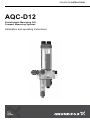
Grundfos AQC-D12 Installation And Operating Instructions Manual
- Tipo
- Installation And Operating Instructions Manual

AQC-D12
Potentiostatic Measuring Cell,
Compact Measuring Systems
Installation and operating instructions
GRUNDFOS INSTRUCTIONS

2

Table of contents
3
AQC-D12
English (GB)
Installation and operating instructions . . . . . . . . . . . . . . . . . . . . . . . . . . . . . . . . . . . . . . . . . . . . . . . . . . . . . . . . . . . 4
Deutsch (DE)
Montage- und Betriebsanleitung . . . . . . . . . . . . . . . . . . . . . . . . . . . . . . . . . . . . . . . . . . . . . . . . . . . . . . . . . . . . . . 24
Español (ES)
Instrucciones de instalación y funcionamiento. . . . . . . . . . . . . . . . . . . . . . . . . . . . . . . . . . . . . . . . . . . . . . . . . . . . 44
Français (FR)
Notice d'installation et de fonctionnement . . . . . . . . . . . . . . . . . . . . . . . . . . . . . . . . . . . . . . . . . . . . . . . . . . . . . . . 64
Magyar (HU)
Telepítési és üzemeltetési utasítás . . . . . . . . . . . . . . . . . . . . . . . . . . . . . . . . . . . . . . . . . . . . . . . . . . . . . . . . . . . . 84
Italiano (IT)
Istruzioni di installazione e funzionamento. . . . . . . . . . . . . . . . . . . . . . . . . . . . . . . . . . . . . . . . . . . . . . . . . . . . . . 104
Nederlands (NL)
Installatie- en bedieningsinstructies . . . . . . . . . . . . . . . . . . . . . . . . . . . . . . . . . . . . . . . . . . . . . . . . . . . . . . . . . . . 124
Polski (PL)
Instrukcja montażu i eksploatacji . . . . . . . . . . . . . . . . . . . . . . . . . . . . . . . . . . . . . . . . . . . . . . . . . . . . . . . . . . . . . 144
Português (PT)
Instruções de instalação e funcionamento. . . . . . . . . . . . . . . . . . . . . . . . . . . . . . . . . . . . . . . . . . . . . . . . . . . . . . 164
Română (RO)
Instrucţiuni de instalare şi utilizare . . . . . . . . . . . . . . . . . . . . . . . . . . . . . . . . . . . . . . . . . . . . . . . . . . . . . . . . . . . . 184
Русский (RU)
Паспорт, Руководство по монтажу и эксплуатации . . . . . . . . . . . . . . . . . . . . . . . . . . . . . . . . . . . . . . . . . . . . . 204
Slovensko (SI)
Navodila za montažo in obratovanje . . . . . . . . . . . . . . . . . . . . . . . . . . . . . . . . . . . . . . . . . . . . . . . . . . . . . . . . . . 224
Türkçe (TR)
Montaj ve kullanım kılavuzu . . . . . . . . . . . . . . . . . . . . . . . . . . . . . . . . . . . . . . . . . . . . . . . . . . . . . . . . . . . . . . . . . 244
Declaration of conformity . . . . . . . . . . . . . . . . . . . . . . . . . . . . . . . . . . . . . . . . . . . . . . . . . . . . . . . . . . . . . . . . . . . 265

English (GB)
4
English (GB) Installation and operating instructions
Original installation and operating instructions
CONTENTS
Page
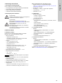
1. Symbols used in this document
1. Symbols used in this document
4
2. Description of preassembled systems with
AQC-D12
5
3. Identification
5
3.1 Nameplate, AquaCell
5
3.2 Type key, AquaCell
6
3.3 Type key, preassembled systems
7
4. Description of AQC-D12
8
5. General information
8
6. Applications
8
7. Safety information
9
7.1 Obligations of the owner
9
7.2 Avoidance of danger
9
8. Technical data
9
8.1 General data
9
8.2 Versions
9
8.3 Measuring ranges
10
8.4 Dimensions / drilling diagram
10
9. Installation
11
9.1 Transport and storage
11
9.2 Unpacking
11
9.3 Installation requirements
11
9.4 Mounting
11
10. Startup
12
10.1 Installation of electrodes and sensors
12
10.2 Checking the position of the cleaning wing
12
10.3 Water connections
13
10.4 Preparing the electrode cable for connection to the
measuring amplifier
13
10.5 Electrical connections
14
10.6 Checks prior to start-up
15
10.7 Switching on
15
10.8 Calibrating the parameters Cl
2
, ClO
2
, O
3
16
11. Operation
18
11.1 Function
18
11.2 Operation
19
11.3 Switching off
19
11.4 Switching on again
19
11.5 Fault finding
20
12. Maintenance
21
12.1 Intervals for cleaning and maintenance
21
12.2 Cleaning and replacing the filter
21
12.3 Cleaning the measuring cell
21
13. Starting up the measuring cell
23
14. Spare parts and accessories
23
14.1 Electrodes, sensors and cables
23
14.2 Other parts
23
15. Disposal
23
Warning
Prior to installation, read these installation and
operating instructions. Installation and operation
must comply with local regulations and accepted
codes of good practice.
Note
These complete installation and operating
instructions are also available on www.grundfos.com.
Warning
If these safety instructions are not observed, it may
result in personal injury.
Caution
If these safety instructions are not observed, it may
result in malfunction or damage to the equipment.
Note
Notes or instructions that make the job easier and
ensure safe operation.

English (GB)
5
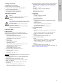
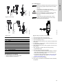
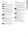
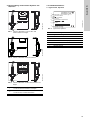
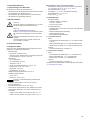
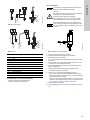
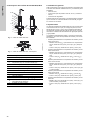
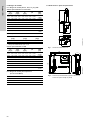
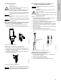
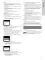
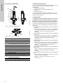
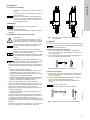
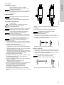
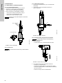
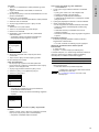
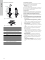
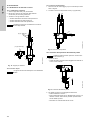
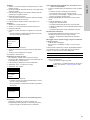
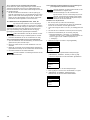
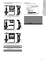
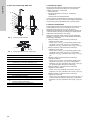
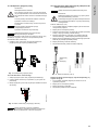
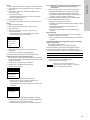
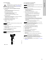
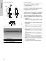
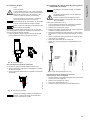
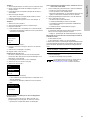
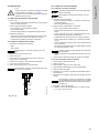
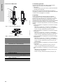
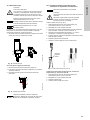
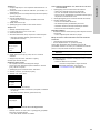
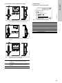
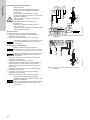
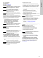
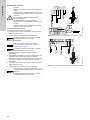
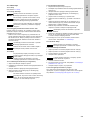
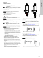
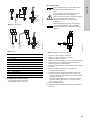
2. Description of preassembled systems with
AQC-D12
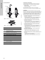
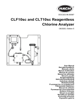
Fig. 1 AQC-D12 measuring cell with Conex DIA / DIS
measuring amplifier and controller
Fig. 2 AQC-D12 measuring cell with sensor interface
Fig. 3 AQC-D12 measuring cell with DIP measuring amplifier
and controller
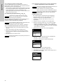
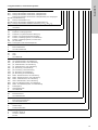
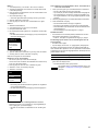
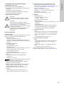
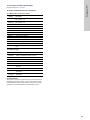
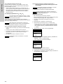
3. Identification
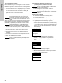
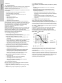
3.1 Nameplate, AquaCell
Fig. 4 Nameplate, AquaCell
TM04 8617 3912
TM04 8618 3912
TM04 8619 3912
1
Conex DIA-1, Conex DIA-2, Conex DIA-2Q, Conex
DIS-D measuring amplifier and controller
2
Sensor interface for Conex DIA-1, Conex DIA-2,
Conex DIA-2Q, for panel-mounting
3 DIP measuring amplifier and controller
Man
Cal
OKEsc
1
2
DIP
Man Cal
OKEsc
Select
Select
3
TM04 8668 3013
Pos. Description
1 Type designation
2 Model
3 Serial number
4 Maximum pressure [bar]
5 Product number
6 Year and week code
7 Country of origin
AQC-D11, P-AU-PCB-RCB, QS-T, H
314-306-10048
S/N: 07/44888
3,00 bar
95737669P11124563516
1
2
4
5
6
7
3

English (GB)
6
3.2 Type key, AquaCell
Example: AQC -D11, P AU-PCB-RCB, QS -T, H
Model
AQC AquaCell
AquaCell type
D11 Pressure-proof, with cleaning motor (Cl
2
, ClO
2
, O
3
)
D12 Pressure-proof, with hydromechanical cleaning (Cl
2
, ClO
2
, O
3
)
D13 Pressureless, with hydromechanical cleaning (Cl
2
, ClO
2
, O
3
)
Pressure-loading valve
P With pressure-loading valve
X Without pressure-loading valve
Electrodes for disinfection parameters
AU Gold
PT Platinum
Electrodes for pH
PCB pH, ceramic diaphragm, with buffer solution
PCX pH, ceramic diaphragm, without buffer solution
PTB pH, PTFE diaphragm, with buffer solution
PTX pH, PTFE diaphragm, without buffer solution
PKB pH, KCl filling, with buffer solution
PKX pH, KCl filling, without buffer solution
PGB pH, gel filling, with buffer solution
PGX pH, gel filling, without buffer solution
X Without electrode
Electrodes for redox potential (ORP)
RCB ORP, ceramic diaphragm, with buffer solution
RCX ORP, ceramic diaphragm, without buffer solution
RTB ORP, PTFE diaphragm, with buffer solution
RTX ORP, PTFE diaphragm, without buffer solution
RRB ORP, without reference system, with buffer solution
RRX ORP, without reference system, without buffer solution
X Without electrode
Water sensor
QS With water sensor
X Without water sensor
Temperature sensor
T With Pt100 temperature sensor
X Without temperature sensor
Power supply
G 230/240 V, 50/60 Hz
H 115/120 V, 50/60 Hz
I 24 VDC
X Without power supply

English (GB)
7
3.3 Type key, preassembled systems
Example: DIA -1 -A D1 P -AU -PCB -QS -T W -H
Measuring amplifier and controller
DIA-1 Dosing Instrumentation Advanced with 1 input
DIA-2 Dosing Instrumentation Advanced with 2 inputs
DIA-2Q Dosing Instrumentation Advanced with 1 input + flow measurement
DIP Dosing Instrumentation Pool
DIS-PR Dosing Instrumentation Standard for pH/ORP measurement
DIS-D Dosing Instrumentation Standard for Cl
2
/ ClO
2
/ O
3
Assembly
APreassembled
Cell type
D11 Pressure-proof, with cleaning motor
D12 Pressure-proof, with hydromechanical cleaning
D13 Pressureless, with hydromechanical cleaning
D4 Pressureless, with cleaning motor, for total chlorine
D5 Pressureless, with cleaning motor, for free chlorine
P/R pH or ORP
PA/HP Peracetic acid or hydrogen peroxide
Pressure-loading valve
P With pressure-loading valve
X Without pressure-loading valve
Electrodes for disinfection parameters
AU Gold
PT Platinum
X Without electrode
Other electrodes
PCB pH, ceramic diaphragm, with buffer solution
PCX pH, ceramic diaphragm, without buffer solution
PTB pH, PTFE diaphragm, with buffer solution
PTX pH, PTFE diaphragm, without buffer solution
PKB pH, KCl filling, with buffer solution
PKX pH, KCl filling, without buffer solution
PGB pH, gel filling, with buffer solution
PGX pH, gel filling, without buffer solution
RCB ORP, ceramic diaphragm, with buffer solution
RCX ORP, ceramic diaphragm, without buffer solution
RTB ORP, PTFE diaphragm, with buffer solution
RTX ORP, PTFE diaphragm, without buffer solution
RRB ORP, without reference system, with buffer solution
RRX ORP, without reference system, without buffer solution
PA Peracetic acid
HP Hydrogen peroxide
X Without electrode
Water sensor
QS With water sensor
X Without water sensor
Temperature sensor
T With Pt100 temperature sensor
X Without temperature sensor
Mounting
W Wall-mounting
P Panel-mounting
Power supply
G 230/240 V, 50/60 Hz
H 115/120 V, 50/60 Hz
I 24 VDC

English (GB)
8
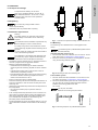
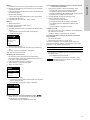
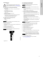
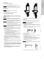
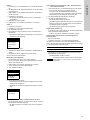
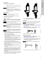
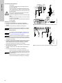
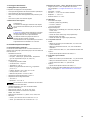
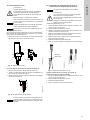
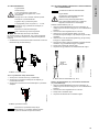
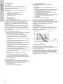
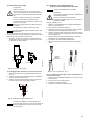
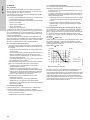
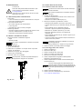
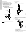
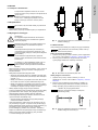
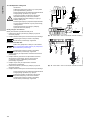
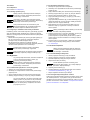
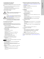
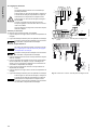
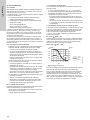
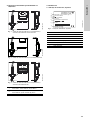
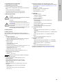
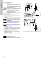
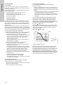
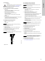
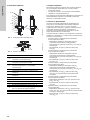
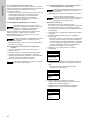
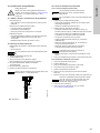
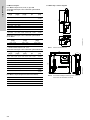
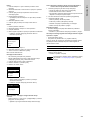
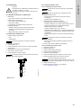
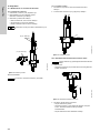
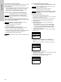
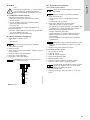
4. Description of AQC-D12
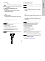
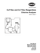
Fig. 5 AQC-D12 measuring cell
Fig. 6 AQC-D12, top view
5. General information
This manual contains all important information for users of the
AQC-D12 and the preassembled systems:
• technical data
• instructions for start-up, use and maintenance
• safety information.
Should you require further information, or should problems occur
which are not handled in sufficient depth in this manual, please
contact Grundfos.
6. Applications
The potentiostatic measuring cell AQC-D12 measures the
concentration of chlorine (Cl
2
) in the pH-range 4.5 to 8.2, chlorine
dioxide (ClO
2
) or ozone (O
3
). By means of the suitable
electrodes, it can also measure the pH value and redox potential
for treatment of swimming-pool water and drinking water.
The preassembled systems measure and control the following
parameters, depending on the measuring amplifier and controller
installed:
• Preassembled system with Conex DIA-1 measuring amplifier
and controller:
– Measurement: free chlorine (Cl
2
), as an option with pH
compensation, chlorine dioxide (ClO
2
), ozone (O
3
), pH,
temperature.
– Control: chlorine (Cl
2
), chlorine dioxide (ClO
2
), ozone (O
3
).
• Preassembled system with Conex DIA-2 measuring amplifier
and controller:
– Measurement: free chlorine (Cl
2
), as an option with pH
compensation, chlorine dioxide (ClO
2
), ozone (O
3
), pH,
temperature.
– Control: chlorine (Cl
2
), chlorine dioxide (ClO
2
), ozone (O
3
),
pH.
• Preassembled system with Conex DIA-2Q measuring amplifier
and controller:
– Measurement: free chlorine (Cl
2
), as an option with pH
compensation, chlorine dioxide (ClO
2
), ozone (O
3
), pH,
temperature.
– Control: chlorine (Cl
2
), chlorine dioxide (ClO
2
), ozone (O
3
),
pH, redox potential.
• Preassembled system with Conex DIS-D measuring amplifier
and controller:
– Measurement: chlorine (Cl
2
), chlorine dioxide (ClO
2
), ozone
(O
3
).
– Control: chlorine (Cl
2
), chlorine dioxide (ClO
2
), ozone (O
3
).
• Preassembled system with DIP measuring amplifier and
controller:
– Measurement: chlorine (Cl
2
), chlorine dioxide (ClO
2
), ozone
(O
3
), pH, redox potential, temperature.
– Control: chlorine (Cl
2
), chlorine dioxide (ClO
2
), ozone (O
3
),
pH.
TM04 8620 3912TM04 8621 3912
Pos. Description
A pH electrode / location for pH electrode
B Redox electrode / location for redox electrode
C
Pt100 temperature sensor / location for temperature
sensor (C1) with screw plug (C2)
D Water sensor
E Connection for sample water inlet
F Connection for sample water outlet
X Sample water shut-off valve
G Regulation of sample water quantity
H Sample water filter
I Sampling cock
J Measuring electrode for Cl
2
, ClO
2
, O
3
K
Reference electrode for Cl
2
, ClO
2
, O
3
/ location for
reference electrode
L Cover with threaded ring
M Acrylic glass cylinder
A / B
L
K
M
X, G
E
J
H
I
G
X
D
C2
F
A / B
KDC

English (GB)
9
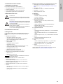
7. Safety information
7.1 Obligations of the owner
The owner of the plant is responsible for
• compliance with country-specific safety regulations
• training of operating personnel
• provision of prescribed protective gear
• implementation of regular maintenance.
7.2 Avoidance of danger
8. Technical data
8.1 General data
The AQC-D12 is a pressure-proof measuring cell with
hydromechanical cleaning for recirculation of sample water.
• Measuring parameters:
– free chlorine, chlorine dioxide, ozone
– optional: pH value, redox potential, temperature (for
compensation of pH, Cl
2
, ClO
2
, O
3
).
• Sample water:
– free of solids
– min. conductivity: 50 µS/cm
– temperature: 0-40 °C
– pH value (only measuring parameter Cl
2
): pH 4.5 - 8.2
– inlet pressure: max. 3 bar, min. 0.2 bar
– counterpressure: max. 3 bar
– pressure difference: approx. 0.2 bar.
• Permissible ambient temperature: 0 to 45 °C.
• Permissible storage temperature:
– -20 to +65 °C
– Electrodes: -10 to +30 °C.
• Permissible humidity: max. 90 % relative humidity (without
condensation).
• Sample water flow rate: min. 20; max. 45 l/h.
• Materials of parts that come into contact with the media:
PMMA, PVC, EPDM.
• Electrode materials: gold, platinum, glass, nickel, PVC.
• Connections:
– inlet: for PVC hose 6/12 or PVC pipe 12 x 1.2
– outlet: for PVC hose 6/12 or PVC pipe 12 x 1.2.
Measuring parameters: chlorine, chlorine dioxide and ozone
• Measuring ranges: Dependent on the measuring amplifier.
See section 8.3.1 Measuring ranges for Cl
2
, ClO
2
, O
3
, pH,
ORP.
• Sensitivity: < 20 ppb.
• Accuracy: < - 5 %/+ 5 % of full-scale value.
• Repeatability: < - 5 %/+ 5 %.
• Response time: t
90
< 60 s.
8.2 Versions
• Power supply:
– 230/240 V, 50/60 Hz (standard)
– 115/120 V, 50/60 Hz
– 24 VDC (not with DIP).
• Equipment/options:
– gold electrode for free chlorine, chlorine dioxide, ozone
(standard)
– platinum electrode
– redox single-rod measuring chain (electrode)
– redox electrode (with DIP)
– pH single-rod measuring chain (electrode).
8.2.1 AquaCell AQC-D12
• Cables:
– connecting cables for the electrodes, 3 m, with free cable
end
– cable for measuring electrode, 2 m, with free cable end
– water sensor with cable, 3 m, with free cable end.
• Options:
– Pt100 temperature sensor with cable, 3 m.
8.2.2 Preassembled systems
• Cables:
– connecting cables for the electrodes, 1 m, preconnected
– cable for measuring electrode, 1.2 m, preconnected
– water sensor with cable, 1 m, preconnected.
• Options:
– Pt100 temperature sensor with cable, 1 m.
Product numbers of the spare parts and optional accessories, see
section 14. Spare parts and accessories.
Warning
Cleaning, maintenance and repairs must only be
carried out by authorised personnel!
Warning
Other applications than those described in section
6. Applications are considered as non-approved and
are not permissible.
Derivates of chloro isocyanuric acid cannot be
measured or controlled.
Grundfos cannot be held liable for any damage
resulting from incorrect use.
Caution
Observe the installation and operating instructions of
the electrodes!

English (GB)
10
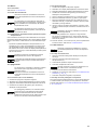
8.3 Measuring ranges
8.3.1 Measuring ranges for Cl
2
, ClO
2
, O
3
, pH, ORP
Preassembled system with Conex DIA
Preassembled system with Conex DIS-D
* Effective measuring range: 0.00 - 5.00
Preassembled system with DIP
8.3.2 Measuring ranges for temperature
(not with Conex DIS-D)
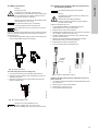
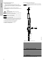
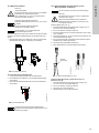
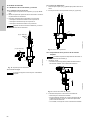
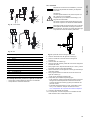
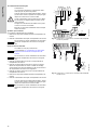
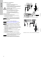
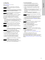
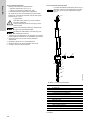
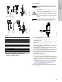
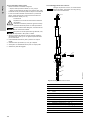
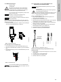
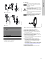
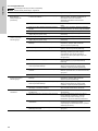
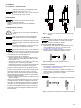
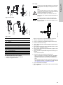
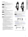
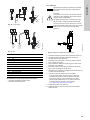
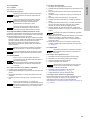
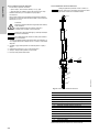
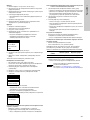
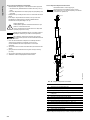
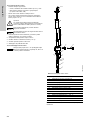
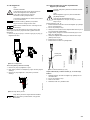
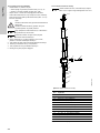
8.4 Dimensions / drilling diagram
Fig. 7 AQC-D12 measuring cell
Fig. 8 Preassembled systems
(example: system with Conex DIA for wall-mounting)
Cl
2
[mg/l]
ClO
2
[mg/l]
O
3
[mg/l]
pH
ORP
[mV]
0.00 - 0.50 0.00 - 0.50 0.00 - 0.50 0.00 - 14.00
-1500 -
+1500
0.00 - 1.00 0.00 - 1.00 0.00 - 1.00 2.00 - 12.00 0-1000
0.00 - 2.00 0.00 - 2.00 0.00 - 2.00 5.00 - 9.00
0.00 - 5.00 0.00 - 5.00 0.00 - 5.00
0.0 - 10.0 0.0 - 10.0
0.0 - 20.0
freely selectable between
0.0 - 50.0 0.0 - 50.0 0.00 - 5.00 0.00 - 14.00
-1500 -
+1500
Cl
2
[mg/l]
ClO
2
[mg/l]
O
3
[mg/l]
0.00 - 2.00 0.00 - 2.00 0.00 - 2.00
0.00 - 20.00 0.00 - 20.00 0.00 - 20.00*
Cl
2
[mg/l]
ClO
2
[mg/l]
O
3
[mg/l]
pH
ORP
[mV]
0.00 - 0.50 0.00 - 0.50 0.00 - 0.50 0.00 - 14.00
-1500 -
+1500
0.00 - 1.00 0.00 - 1.00 0.00 - 1.00 2.00 - 12.00 0-1000
0.00 - 2.00 0.00 - 2.00 0.00 - 2.00 5.00 - 9.00
0.00 - 5.00 0.00 - 5.00 0.00 - 5.00
0.0 - 10.0 0.0 - 50.0
0.0 - 30.0
freely selectable between
0.0 - 30.0 0.0 - 50.0 0.00 - 5.00 0.00 - 14.00
-1500 -
+1500
°C °F
0 to +50 32 to 122
0 to +100 32 to 212
-5 to +120 23 to 248
TM04 8622 3912TM04 8623 3912
365
105
120
125
137
475
495
475
133
117
Man
Cal
OKEsc
495

English (GB)
11
9. Installation
9.1 Transport and storage
9.2 Unpacking
• Check scope of delivery.
• Assemble as soon as possible after unpacking.
9.3 Installation requirements
• The location must be vibration-free, dry, dust-free and free of
corrosive, pungent fumes or aggressive solvents.
• Maximum permissible cable length:
– Individual AQC-D12 measuring cell: distance between
measuring cell and measuring amplifier or sensor interface
3 m.
– Preassembled systems with Conex DIS, DIA or DIP for
wall-mounting: completely prewired.
– Preassembled systems with Conex DIA for panel-mounting:
the distance between measuring amplifier and sensor
interface must be less than 100 m.
• Ensure a continuous supply of sample water.
• Install the measuring cell so that the sample water feed line is
as short as possible, in order to reduce the delay time of the
measuring cell.
• Observe the permissible inlet pressure and counterpressure of
the sample water.
– Fit a pressure booster pump or pressure reducer, if
necessary.
• If the counterpressure may fall below 0.3 bar or if there is an
open outflow, a pressure-loading valve must be fitted to the
outlet of the measuring cell (F). The pressure-loading valve
(V) is available with an adaptor for the measuring cell
(Grundfos product number 99253231).
• Provide possibilities to shut-off the sample water (U). You can
use the Grundfos installation set 95727420 on the discharge
side.
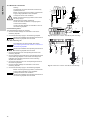
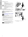
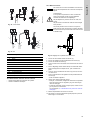
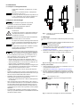
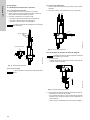
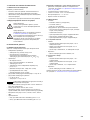
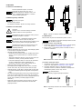
Fig. 9 AQC-D12 with pressure-loading valve / installation set
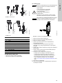
9.4 Mounting
The measuring cell is fastened to the mounting plate at the
factory.
Individual AQC-D12 measuring cell
1. Drill two dowel holes with a diameter of 8 mm and min. 50 mm
deep. See section 8.4 Dimensions / drilling diagram.
2. Mount the measuring cell and the mounting plate on the wall
using the mounting material provided.
Fig. 10 Mounting of AQC-D12 measuring cell
Preassembled systems
1. Drill four dowel holes with a diameter of 10 mm and min. 60
mm deep. See section 8.4 Dimensions / drilling diagram.
2. Mount the preassembled system and the mounting plate on
the wall using the mounting material provided. Distance
between the mounting plate and the wall:
min. 20 mm.
Fig. 11 Mounting sequence for preassembled systems
Caution
Transport device carefully, do not throw.
Store in dry conditions between -20 and +65 °C.
Store electrodes between -10 and +30 °C. Keep
protective caps moist with 3-molar potassium
chloride solution.
Caution
Do not allow any foreign bodies to enter!
Warning
For safety reasons, the customer must install an
earth leakage circuit breaker for the measuring
amplifier.
Caution
Non-observance of the installation requirements may
result in damage or errors in measurement!
Note
For safety during service and maintenance, switch
off the measuring amplifier and the measuring cell at
all poles.
For easy switch-off, install an all-pole mains switch in
front of the measuring amplifier.
Note
The installation of the sample-water feed pipe must
not contain any copper. Copper interferes with the
measurement and can damage the electrodes.
TM04 8624 3912
Caution
The measuring cell or preassembled system must be
mounted vertically!
TM03 5856 1106
Caution
Do not pinch the cable!
Observe the mounting sequence below.
TM03 5857 1106
F
V
U
F
20 mm

English (GB)
12
10. Startup
10.1 Installation of electrodes and sensors
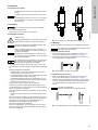
10.1.1 Fitting of electrodes
1. Unscrew the plugs of the holders (A, B) to be used.
2. Remove the protective caps from the electrodes. Keep them
for electrode removal.
3. Screw the electrodes into the holders by hand.
– Screw reference electrode in location K.
– Screw pH electrode in location A.
– Screw redox electrode in location B.
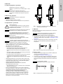
Fig. 12 Holders for electrodes
10.1.2 Water sensor
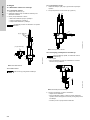
10.1.3 Temperature sensor
1. Remove lock screw (C2), store for later use.
2. Screw in Pt100 temperature sensor (C1) (optional).
Fig. 13 Temperature sensor
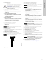
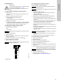
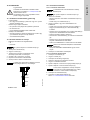
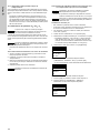
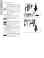
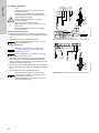
10.2 Checking the position of the cleaning wing
1. Visual inspection:
– The cleaning wing (S) must be seated on the measuring
electrode as shown.
Fig. 14 Position of the cleaning wing
2. If the cleaning wing is not seated correctly:
– Screw out the measuring electrode.
– Insert cleaning wing into the bore of the measuring electrode
using the entry pilot. It must be possible to freely move the
cleaning wing.
– Carefully screw in the measuring electrode again.
Caution
Observe the installation and operating instructions of
the electrodes!
TM04 8625 3912
Note
The water sensor is next to the cleaning wing.
pH (A) / Redox (B)
K
pH (A) / Redox (B)
J
F
E
E
TM04 8626 3912
Caution
The cleaning wing falls out when the measuring
electrode (J) is removed.
TM04 8627 3912
C
C2
S
J

English (GB)
13
10.3 Water connections
If the counterpressure may fall below 0.3 bar or if there is an open
outflow, a pressure-loading valve must be fitted to the outlet of
the measuring cell.
1. Connect the sample water inlet and outlet to the connections
for the sample water inlet (E) and outlet (F).
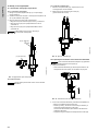
Fig. 15 Water connections
10.3.1 Mounting the pressure-loading valve
1. Unscrew the connection of the sample water outlet (F).
2. Screw the pressure-loading valve and adaptor (V) onto the
measuring cell outlet.
3. Screw the connection of the sample water outlet onto the
pressure-loading valve.
Fig. 16 Pressure-loading valve
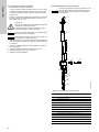
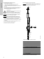
10.4 Preparing the electrode cable for connection to
the measuring amplifier
Cables for electrodes (A, B, K)
1. Cut the electrode cables to the desired length plus
approximately 80 mm for the connections.
2. Remove 80 mm of the outer insulation.
3. Disentangle the braided screen until you reach the next part of
the insulation, and twist it to form a wire.
4. Strip the braided screen (for instance using a shrink hose),
and fit a wire end ferrule.
5. Remove the black (conductive) sheath of the insulated
electrode wire until you reach the insulation.
6. Dismantle the end of the electrode wire.
7. Fit a wire end ferrule to the electrode wire.
Fig. 17 Cable for electrodes (A, B, K)
Cable for measuring electrode (D), temperature sensor (C),
water sensor (D)
1. Cut cables to the desired length plus approximately 65 mm for
the connections.
2. Remove 65 mm of the outer insulation.
3. Dismantle the end of the wires.
4. Fit wire end ferrules to the wires.
Warning
Danger of injuries!
At a pressure of more than 3 bar and if the
measuring cell is not deaerated, the cell might burst.
Do not exceed the max. system pressure of 3 bar.
Fit pressure reducer, if necessary.
Caution
Observe the local pressure! The permissible primary
water pressure is 0.3 to 3.0 bar.
Fit a pressure booster pump, if necessary.
Check the tightness of the measuring cell.
Caution
Only tighten the union nut by hand. Do not use any
tools!
TM04 8628 3912TM04 8788 1313
Caution
Observe the correct installation of the
pressure-loading valve. The arrow on the
pressure-loading valve must point in flow direction!
F
E
E
F
V
Note
The preassembled systems are prewired.
Warning
The electrical connection should be carried out by
qualified personnel!
Observe the local safety regulations!
Protect the cable connections and plugs against
corrosion and humidity.
TM03 5868 1106
TM03 5869 1106
70 10
Insulated
braided
screen

English (GB)
14
10.5 Electrical connections
Preassembled systems
The preassembled systems are prewired.
1. Connect an earth leakage circuit breaker in front of the
measuring amplifier.
2. Connect the electricity supply to the measuring amplifier.
AQC-D12 measuring cell
1. Connect electrodes to the corresponding terminals of the
measuring amplifier.
2. Connect measuring electrodes to the corresponding terminals
of the measuring amplifier. Fit the screen according to the
installation and operating instructions of the measuring
amplifier and controller.
3. Connect the water sensor to the corresponding terminals of
the measuring amplifier.
4. Connect an earth leakage circuit breaker in front of the
measuring amplifier.
5. Connect the electricity supply to the measuring amplifier.
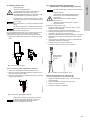
Fig. 18 Conex DIA-1 / DIA-2 / DIA-2Q for panel-mounting
Fig. 19 Conex DIA-1 / DIA-2 / DIA-2Q for wall-mounting
Warning
The electrical connection should be carried out by
qualified personnel!
Before connecting the supply cables, check that the
supply voltage specified on the nameplate
corresponds to the local conditions!
Before connecting the supply cables, switch off the
electricity supply!
Observe the local safety regulations!
Protect the cable connections and plugs against
corrosion and humidity.
Connect an earth leakage circuit breaker in front of
the measuring amplifier.
Caution
Observe the installation and operating instructions of
the measuring amplifier and controller!
Note
The cables are not preconnected. See section
10.4 Preparing the electrode cable for connection to
the measuring amplifier.
Caution
Observe the installation and operating instructions of
the measuring amplifier and controller!
Caution
Before connecting the supply cables, check that the
supply voltage specified on the nameplate
corresponds to the local conditions!
Observe the installation and operating instructions of
the measuring amplifier and controller!
TM04 8629 3912TM04 8630 3912
1/11
1/13
4/1
1/12 1/14
4/3
4/2
4/4
3/1 3/3
3/2 3/4
B
A
1
4
Conex
2/3
2/4
+
-
12
MB/RG/C
7
1
6
Pt 100
2
8
9
1
4
11
8
11
12
9
9
10
Sensorinterface
7
1
37
38
39 40 41 42
6
12
4
1
15 17
19
21 23 25 27 29 31 33 35
363432302826242220
18
16
9
8
2
1
4
11
8
11
12
9
9
10

English (GB)
15
Fig. 20 Conex DIS-D
Fig. 21 DIP
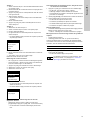
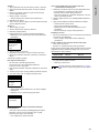
10.6 Checks prior to start-up
• Check the tightness of the whole system.
• Check the electrical connections.
10.7 Switching on
Fig. 22 Setting the quantity of sample water
1. Close the sample water shut-off valve (X).
2. Close the regulation of sample water quantity (G).
3. Close the sampling cock (I).
4. Open the inlet and outlet side of the customer's sample water
connection.
5. For deaeration, loosen the pH or redox electrode until the air
has escaped, then fasten it.
6. Open sample water shut-off valve (X) approx. two turns up to
the limit stop.
7. Open regulation of sample water quantity (G) slowly.
– Avoid turbulent flow!
8. Check that the cleaning wing (S) rotates.
– Try, if necessary, to briefly increase the quantity of sample
water with the regulation of sample water quantity (G) in
order to move the cleaning wing.
– If the cleaning wing still does not rotate, check and correct
its position, if necessary. See section 10.2 Checking the
position of the cleaning wing.
9. Switch on the measuring amplifier.
10. Only switch on the device controlled after the first calibration,
if applicable.
TM04 8631 3912TM04 8632 3912
Pos. Description
1Brown
2White
3Black
4Blue
6 Outer conductor (screen)
7 Inner conductor
8 Reference electrode
9 Measuring electrode with counter-electrode
10 Counter-electrode
11 Pt100 temperature sensor (not with Conex DIS-C)
12 Water sensor
7
1
6
9
8
2
20 2122
19
12
4
1
14 16
8
12
9
9
10
7
1
6
12
4
9
8
2
1
4
1
53
55 57
54 56 58
63 65
64
66
11
8
11
12
9
9
10
Caution
Observe the installation and operating instructions of
the measuring amplifier and the device controlled!
Warning
At a pressure of more than 3 bar and if the
measuring cell is not deaerated, the cell might burst.
Ensure draining and deaeration.
Do not exceed the max. system pressure of 3 bar.
Do not put a damaged measuring cell under
pressure!
Caution
At first start-up or after long-term stop: Let the
system run for at least two hours to avoid faulty
measurements and calibration!
TM04 8633 3912
I
GX

English (GB)
16
10.7.1 Setting the quantity of sample water
A correct measurement can only be taken, if the quantity of
sample water is within a defined range. This range is from 200 to
800 rotations/minute of the cleaning wing.
• Set the quantity of sample water with the regulation (G) so that
the measuring amplifier shows a sample water flow rate of 200
to 800 rotations/minute. The bar in the display of the
measuring amplifier shows the range. The exact speed can be
taken from the service menu.
10.8 Calibrating the parameters Cl
2
, ClO
2
, O
3
Due to the electro-chemical behaviour of the measuring cell, no
zero-point adjustment is necessary. Only the rate of rise
(sensitivity) must be adjusted during calibration.
• Check the calibration after 24 hours. Repeat, if necessary.
10.8.1 Photometrical determination of a reference value
1. Open the sampling cock (I), and let the water run for a few
seconds.
2. Take a water sample, and close the sampling cock.
3. Determine the concentration of the measuring parameter
photometrically, for instance using the Grundfos DIT hand
photometer.
4. Keep this value as a reference value.
10.8.2 Calibration example based on chlorine measurement
with pH compensation (not with Conex DIS-D)
• Define the basic settings for the measuring amplifier.
Calibrating the pH value
• DIP: Push the button underneath the right-hand display.
• Conex DIA and DIP: Use the [CAL] button to select the
calibration function CAL. The LED illuminates.
1. If necessary, enter the code number for CAL (or full)
authorisation.
2. Change to the menu "calibration" with the [OK] button.
3. Select the measured variable "pH", and confirm with [OK].
– Selection possibilities: "cal. meas. value" (= measured
value), "cal. result" and "cal. cycle" (= count-down function
which triggers the alarm "calibrate sensor" after a selectable
time interval of 1-100 days).
4. Select the line "cal. meas. value" with [UP]/[DOWN].
5. Select one of the defined buffer solutions ("GRUNDFOS",
"DIN/NIST", "others"), and press [OK].
– The menu "temperature" is selected automatically.
6. Enter the temperature of the buffer solutions.
7. Press [OK] to jump to the menu "buffer value 1".
8. "GRUNDFOS" or "DIN/NIST" buffer solutions: Select one of
the available buffer values.
Caution
At first start-up or after long-term stop: Let the
system run for at least two hours to avoid faulty
measurements and calibration!
Caution
During calibration: Keep pH value, sample water flow
rate and water temperature constant.
Caution
Observe the installation and operating instructions of
the photometer!
Caution
Observe the installation and operating instructions of
the measuring amplifier and controller!
Note
When carrying out a chlorine measurement with pH
compensation, the pH value must be calibrated first,
since the pH value is used when calibrating the
chlorine value!
pH
cal. meas. value
cal. result
cal. cycle
buffer
GRUNDFOS
DIN/NIST
others
buffer value 1
4.01 pH
7.00 pH
9.18 pH

English (GB)
17
Buffer 1
1. Fill buffer solution 1 from the supply bottle into a clean vessel.
2. Remove the electrode from the measuring cell, and immerse
in the buffer solution.
3. Press [OK] to read in the temperature of the sample water and
the measured signal.
4. Discard buffer solution 1.
– Do not return the used buffer solution to the supply bottle!
5. Flush electrode with water.
6. Press [OK] to jump to the menu "buffer value 2".
Buffer 2
1. Select buffer value 2.
2. Fill buffer solution 2 into a clean vessel.
3. Immerse the electrode.
4. The measured signal is read in and compared with the buffer
values.
– The calibration result (sensor slope and asymmetry
potential) is displayed.
5. Discard buffer solution 2.
6. Flush the electrode with water, and return to the measuring
cell.
7. Go back to the menu "calibration" with [ESC].
Then calibrate the chlorine value.
Calibrating the chlorine value
• DIP: Push the button underneath the left-hand display.
• Conex DIA and DIP: Select the calibration function with the
[CAL] button. The LED illuminates.
1. Press [OK] to select the menu "calibration".
2. Select "chlorine", and confirm with [OK].
3. Select "cal. meas. value".
4. Enter the reference value.
– The measured signal is read in automatically and compared
with the reference value.
– The calibration result (sensor slope) is displayed.
Reading calibration data in the diagnostics menu "service"
• Select "service" in the "main menu" with [UP]/[DOWN], and
press [OK] (DIP: on both displays).
– The data of the last 10 calibrations can be read.
10.8.3 Calibrating the parameters chlorine, chlorine dioxide
or ozone with Conex DIS-D
1. Press the [CAL] button to select the calibration menu.
– The CAL LED next to the [CAL] button illuminates.
– The display shows the current measured value.
– To prevent overdosing, the controllers must be switched off,
and the device controlled must be closed.
2. Use [UP]/[DOWN] to select the reference value.
3. Start the calibration with [OK].
– The sensor data are then read in.
– The slope (sensitivity) of the sensor is calculated.
– The calibration result is displayed immediately after
calibration.
– The sensor slope is displayed in µA/ppm.
Calibration result
• The result of the current (last) calibration can be displayed in
the code menu at any time:
– Code 51: display of calibrated slope in µA/ppm.
Error message when reading in the current signal of the
sensor system
• The alarm LED flashes.
• The display shows code *13* (slope error).
The alarm is triggered, if the plausibility check results in an
upward or a downward violation of the following slope ranges,
depending on the selected measuring cell:
• Press [OK] to acknowledge the error message and to return to
the display level.
– The calibration data are imported.
CALDATA pH
slope
- 60.17 mV/pH
asym.pot
19 mV
chlorine
cal. meas. value
cal. result
cal. cycle
CALDATA chlorine
slope
34.67 µA/ppm
Measuring cell Lower limit Upper limit
AQC-D12 2.5 µA/ppm 70.0 µA/ppm
Note
The controller is operating in emergency mode!
Eliminate the fault, see section 11.5 Fault finding,
and calibrate again!

English (GB)
18
11. Operation
11.1 Function
Various oxidation agents are used for the disinfection of
swimming-pool water and drinking water, for instance chlorine
(Cl
2
), chlorine dioxide (ClO
2
) and ozone (O
3
).
It is necessary to measure the concentration of the oxidation
agent and to regulate its dosing.
• Concentration of oxidation agent is too low:
– Disinfection effect is too weak.
• Concentration of oxidation agent is too high:
– Danger to health
– Unpleasant odour and taste
– Corrosion damage
– Increased operating costs.
The AQC-D12 measuring cell is used for measuring the
concentration of chlorine (Cl
2
), chlorine dioxide (ClO
2
) or ozone
(O
3
). It is equipped with a water sensor, an optional Pt100
temperature sensor and additional holders for pH electrodes and
redox electrodes.
Preassembled systems with Conex DIA, Conex DIS and DIP are
used when the values of decontamination agents, pH and
redox-potential have to be determined and controlled. The basic
element of the preassembled systems is the AQC-D12 measuring
cell.
11.1.1 Functional principle of measurement
• Sample water is taken at a representative position and passed
to the measuring cell via an integral filter.
– The water flow rate can be adjusted on the measuring cell.
– A water sensor serves to trigger an alarm or to switch off the
control function, if there is a sample water deficiency. It is
also used for checking the cleaning wing.
– The agent to be determined (Cl
2
, ClO
2
or O
3
) is measured at
the gold or platinum electrode.
• The agent to be determined generates an electric current in
the µA range, proportional to its concentration.
– The measuring cell is controlled by a potentiostat in the
measuring amplifier.
– A constant voltage is applied to the measuring electrode. An
exactly defined potential of the measuring electrode is
retained by means of the reference electrode. This results in
a linear response for the measuring cell as well as a stable
zero point for the measurement.
• The Conex or DIP measuring amplifiers and controllers
– amplify the current
– calculate it using the calibration parameters
– display the concentration as a digital value
– control a gas dosing unit or a dosing pump (device
controlled).
11.1.2 Electrode cleaning
The measuring electrode and the counter-electrode are
continuously cleaned of deposits by a cleaning wing.
• This ensures uniform sensitivity for the measuring cell over a
long period.
• The cleaning wing is driven hydraulically.
11.1.3 Influence of temperature
The current generated on the electrodes depends on the
temperature of the sample water.
• The measured value increases by approx. 4 % per 1 °C
increase.
• Temperature variations can be compensated by the measuring
amplifier, if the temperature compensation function is
activated.
– The temperature can be measured with a Pt100 temperature
sensor optionally integrated into the measuring electrode.
– The temperature measuring signals are transferred to the
measuring amplifier and calculated using the electrode
signals.
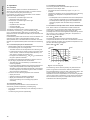
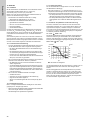
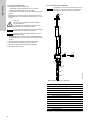
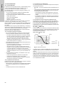
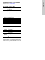
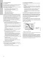
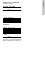
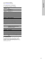
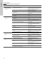
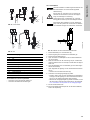
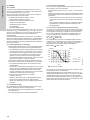
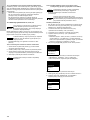
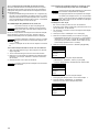
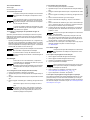
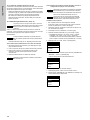
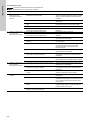
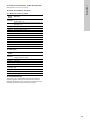
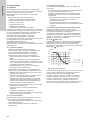
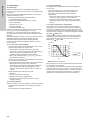
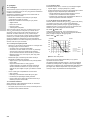
11.1.4 Influence of the pH value on the chlorine measurement
Free, active chlorine is considered as the total of molecular
chlorine gas (Cl
2
), hypochlorous acid (HOCl) and hypochlorite
anions (OCl
-
). Dissolved chlorine gas in molecular form
practically does not exist at the application-dependent pH values
(pH 4.5 to 8.2), but is subject to hydrolysis in the presence of
water according to the equation
Cl
2
+ H
2
O HOCl + HCl
The resulting hypochlorous acid is the actually effective
compound for disinfection of the water. The dissociation of acid to
anions is primarily according to an equilibrium dependent on the
pH value according to the equation
HOCl + H
2
O H
3
O
+
+ OCl
-
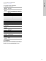
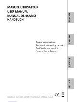
Fig. 23 HOCl-OCl diagram
The measuring cell for chlorine primarily only determines the
portion of hypochlorous acid that is relevant for disinfection.
Since the dependence on the pH value is particularly large in the
actually relevant range between pH 7 and pH 8.2, this
dependence must be compensated for in the measuring amplifier
if the pH value varies considerably. The pH value must therefore
also be measured, and the pH compensation function must be
activated on the measuring amplifier.
TM03 5879 1106
4
100
% HOCl
80
60
40
20
0
0
20
40
60
80
100
% OCl
-
pH
0 °C
10 °C
30 °C
OCl
-
HOCl
5
6
7
89
10 11

English (GB)
19
11.2 Operation
11.2.1 Switching on
See section
10.7 Switching on.
11.2.2 Operating state
11.2.3 Adjusting / setting the quantity of sample water
A correct measurement can only be taken, if the quantity of
sample water is within a defined range. This range is from 200 to
800 rotations/minute of the cleaning wing.
• Set the quantity of sample water with the regulation (G) so that
the measuring amplifier shows a sample water flow rate of 200
to 800 rotations/minute. The bar in the display of the
measuring amplifier shows the range. The exact speed can be
taken from the service menu.
11.3 Switching off
11.3.1 Short-term stop (up to one week)
1. Close and/or switch off the device controlled.
2. Wait until the display of the measuring amplifier is at zero.
3. Switch off the electricity supply to the measuring amplifier.
4. Close the connection to the sample water inlet (E) and outlet
(F).
11.3.2 Long-term stop
1. Close and/or switch off the device controlled.
2. Wait until the display of the measuring amplifier is at zero.
3. Switch off the electricity supply to the measuring amplifier.
4. Close the connection to the sample water inlet (E) and outlet
(F).
5. Open the sampling cock (I), and drain water.
6. Remove the measuring electrode (J), clean and store dry.
7. Remove the reference electrode (K), and remove the pH
electrode (A) and redox electrode (B), if applicable. Fit thread
protection caps, and clean the electrodes.
8. Fit protective caps on the electrodes. The protective caps
must be filled with 3-molar potassium chloride solution.
9. Store electrodes with protective caps in a dry place. If they are
stored for an extended period of time, it may be necessary to
add 3-molar potassium chloride solution after a while.
10. Before starting up again, and if it is very dirty, clean the whole
measuring cell. See section
12. Maintenance.
11.4 Switching on again
11.4.1 After short-term stop
1. Open the connection to the sample water inlet (E).
2. Open the connection to the sample water outlet (F).
3. Check the quantity of sample water.
4. Switch on the measuring amplifier.
5. Take a reference measurement.
6. Recalibrate, if necessary. See section
10.8 Calibrating the
parameters Cl
2
, ClO
2
, O
3
.
7. Switch on the device controlled, if applicable.
11.4.2 After long-term stop / inspection
If the measuring cell has been switched off for a long period of
time or has been emptied, for instance for inspection, it is
necessary to start up the measuring cell. See section
10.6 Checks prior to start-up and 10.7 Switching on.
Caution
Observe the installation and operating instructions of
the measuring amplifier and the device controlled!
Note
For information on operation of the measuring cell in
the operating state, please see the installation and
operating instructions of the relevant measuring
amplifier.
Caution
The measuring cell may be damaged if the reference
electrode (K) is not connected, and the electricity
supply is switched on!
Caution
Observe the installation and operating instructions of
the measuring amplifier and controller!
Note
The delay time of the measuring cell can be reduced
by increasing the sample water flow rate.
Caution
To avoid a dosing error, the device controlled must
be switched off each time the measuring system is
switched off.
Observe the installation and operating instructions of
the measuring amplifier and the device controlled!
Caution
To protect the electrodes, do not drain the water!
Make sure that the water level in the measuring cell
is sufficiently high for the reference electrode (K) to
be immersed at least 2 cm during device stop.
Caution
Observe the installation and operating instructions of
the electrodes!
Caution
Observe the installation and operating instructions of
the measuring amplifier and the device controlled!
Caution
Let the system run for at least two hours to avoid
faulty measurements and calibrations!

English (GB)
20
11.5 Fault finding
Caution
Observe the installation and operating instructions of
the measuring amplifier and controller!
Fault Cause Remedy
1. No display. No electricity
supply to the measuring
cell.
a) A disinfection or oxidation agent is missing in the
sample water.
Check the concentration by making a reference
measurement. Check the dosing units, and
activate dosing. Check the settings of the
measuring amplifier.
b) The electrode cable connection is interrupted. Remake the connection. Replace damaged
cables.
c) No or too low sample water flow rate. Clean the filter, check the flow rate, and check
the sample water inlet pressure.
d) The measuring electrode is faulty. Replace the measuring electrode.
e) The measuring electrode is contaminated or made
passive by deposits.
Dismantle, clean or replace the measuring
electrode.
2. The measured value is
lower than the reference
measurement.
a) The measuring electrode is faulty. Replace the measuring electrode.
b) The measuring electrode is contaminated or made
passive by deposits.
Remove, clean or replace the measuring
electrode.
c) The temperature has fallen since the calibration. Activate the automatic temperature
compensation, if applicable. Recalibrate.
d) The system has run too short time prior to
calibration.
Let the system run for at least two hours.
Recalibrate.
e) Unsuitable chlorination agent. Only use chlorine solutions such as chloric gas,
sodium hypochlorite and chlorinated lime. Do
not use organic products such as
trichloroisocyanuric acid.
f) Incorrect reference measurement during
calibration.
Check the reference measurement, and take
another measurement. Recalibrate.
g) The pH value for the chlorine measurement has
risen since the calibration.
Keep the pH value constant. Activate the pH
value compensation, if applicable. Recalibrate.
h) The quantity of sample water is set too low. Check and set the quantity of sample water.
Check the filter, and clean it, if necessary.
i) The cleaning wing is blocked. Fit the cleaning wing correctly.
3. The measured value is
higher than the reference
measurement.
a) The temperature has risen since the calibration. Activate the automatic temperature
compensation, if applicable. Recalibrate.
b) The pH value for the chlorine measurement has
fallen since the calibration.
Keep the pH value constant. Activate the pH
value compensation, if applicable. Recalibrate.
c) Interference by other oxidation agents in the
sample water.
Analyse the sample water. Check the chemicals
used.
4. The measured value is
unstable.
a) Interferences on the signal lines. Check the screen and the connections to the
amplifier.
b) The reference electrode diaphragm is blocked. Clean the diaphragm (on the side at the bottom
of the reference electrode) using diluted
hydrochloric acid (10 %). Replace the reference
electrode, if necessary.
c) The measuring electrode is contaminated or faulty. Clean the measuring electrode using a diluted
abrasive cleaning agent. Replace measuring
electrode, if necessary.
d) The filter is contaminated, and the quantity of
sample water is therefore too low.
Check the filter, and clean it, if necessary.
A página está carregando...
A página está carregando...
A página está carregando...
A página está carregando...
A página está carregando...
A página está carregando...
A página está carregando...
A página está carregando...
A página está carregando...
A página está carregando...
A página está carregando...
A página está carregando...
A página está carregando...
A página está carregando...
A página está carregando...
A página está carregando...
A página está carregando...
A página está carregando...
A página está carregando...
A página está carregando...
A página está carregando...
A página está carregando...
A página está carregando...
A página está carregando...
A página está carregando...
A página está carregando...
A página está carregando...
A página está carregando...
A página está carregando...
A página está carregando...
A página está carregando...
A página está carregando...
A página está carregando...
A página está carregando...
A página está carregando...
A página está carregando...
A página está carregando...
A página está carregando...
A página está carregando...
A página está carregando...
A página está carregando...
A página está carregando...
A página está carregando...
A página está carregando...
A página está carregando...
A página está carregando...
A página está carregando...
A página está carregando...
A página está carregando...
A página está carregando...
A página está carregando...
A página está carregando...
A página está carregando...
A página está carregando...
A página está carregando...
A página está carregando...
A página está carregando...
A página está carregando...
A página está carregando...
A página está carregando...
A página está carregando...
A página está carregando...
A página está carregando...
A página está carregando...
A página está carregando...
A página está carregando...
A página está carregando...
A página está carregando...
A página está carregando...
A página está carregando...
A página está carregando...
A página está carregando...
A página está carregando...
A página está carregando...
A página está carregando...
A página está carregando...
A página está carregando...
A página está carregando...
A página está carregando...
A página está carregando...
A página está carregando...
A página está carregando...
A página está carregando...
A página está carregando...
A página está carregando...
A página está carregando...
A página está carregando...
A página está carregando...
A página está carregando...
A página está carregando...
A página está carregando...
A página está carregando...
A página está carregando...
A página está carregando...
A página está carregando...
A página está carregando...
A página está carregando...
A página está carregando...
A página está carregando...
A página está carregando...
A página está carregando...
A página está carregando...
A página está carregando...
A página está carregando...
A página está carregando...
A página está carregando...
A página está carregando...
A página está carregando...
A página está carregando...
A página está carregando...
A página está carregando...
A página está carregando...
A página está carregando...
A página está carregando...
A página está carregando...
A página está carregando...
A página está carregando...
A página está carregando...
A página está carregando...
A página está carregando...
A página está carregando...
A página está carregando...
A página está carregando...
A página está carregando...
A página está carregando...
A página está carregando...
A página está carregando...
A página está carregando...
A página está carregando...
A página está carregando...
A página está carregando...
A página está carregando...
A página está carregando...
A página está carregando...
A página está carregando...
A página está carregando...
A página está carregando...
A página está carregando...
A página está carregando...
A página está carregando...
A página está carregando...
A página está carregando...
A página está carregando...
A página está carregando...
A página está carregando...
A página está carregando...
A página está carregando...
A página está carregando...
A página está carregando...
A página está carregando...
A página está carregando...
A página está carregando...
A página está carregando...
A página está carregando...
A página está carregando...
A página está carregando...
A página está carregando...
A página está carregando...
A página está carregando...
A página está carregando...
A página está carregando...
A página está carregando...
A página está carregando...
A página está carregando...
A página está carregando...
A página está carregando...
A página está carregando...
A página está carregando...
A página está carregando...
A página está carregando...
A página está carregando...
A página está carregando...
A página está carregando...
A página está carregando...
A página está carregando...
A página está carregando...
A página está carregando...
A página está carregando...
A página está carregando...
A página está carregando...
A página está carregando...
A página está carregando...
A página está carregando...
A página está carregando...
A página está carregando...
A página está carregando...
A página está carregando...
A página está carregando...
A página está carregando...
A página está carregando...
A página está carregando...
A página está carregando...
A página está carregando...
A página está carregando...
A página está carregando...
A página está carregando...
A página está carregando...
A página está carregando...
A página está carregando...
A página está carregando...
A página está carregando...
A página está carregando...
A página está carregando...
A página está carregando...
A página está carregando...
A página está carregando...
A página está carregando...
A página está carregando...
A página está carregando...
A página está carregando...
A página está carregando...
A página está carregando...
A página está carregando...
A página está carregando...
A página está carregando...
A página está carregando...
A página está carregando...
A página está carregando...
A página está carregando...
A página está carregando...
A página está carregando...
A página está carregando...
A página está carregando...
A página está carregando...
A página está carregando...
A página está carregando...
A página está carregando...
A página está carregando...
A página está carregando...
A página está carregando...
A página está carregando...
A página está carregando...
A página está carregando...
A página está carregando...
A página está carregando...
A página está carregando...
A página está carregando...
A página está carregando...
A página está carregando...
A página está carregando...
A página está carregando...
A página está carregando...
A página está carregando...
A página está carregando...
A página está carregando...
A página está carregando...
A página está carregando...
A página está carregando...
-
 1
1
-
 2
2
-
 3
3
-
 4
4
-
 5
5
-
 6
6
-
 7
7
-
 8
8
-
 9
9
-
 10
10
-
 11
11
-
 12
12
-
 13
13
-
 14
14
-
 15
15
-
 16
16
-
 17
17
-
 18
18
-
 19
19
-
 20
20
-
 21
21
-
 22
22
-
 23
23
-
 24
24
-
 25
25
-
 26
26
-
 27
27
-
 28
28
-
 29
29
-
 30
30
-
 31
31
-
 32
32
-
 33
33
-
 34
34
-
 35
35
-
 36
36
-
 37
37
-
 38
38
-
 39
39
-
 40
40
-
 41
41
-
 42
42
-
 43
43
-
 44
44
-
 45
45
-
 46
46
-
 47
47
-
 48
48
-
 49
49
-
 50
50
-
 51
51
-
 52
52
-
 53
53
-
 54
54
-
 55
55
-
 56
56
-
 57
57
-
 58
58
-
 59
59
-
 60
60
-
 61
61
-
 62
62
-
 63
63
-
 64
64
-
 65
65
-
 66
66
-
 67
67
-
 68
68
-
 69
69
-
 70
70
-
 71
71
-
 72
72
-
 73
73
-
 74
74
-
 75
75
-
 76
76
-
 77
77
-
 78
78
-
 79
79
-
 80
80
-
 81
81
-
 82
82
-
 83
83
-
 84
84
-
 85
85
-
 86
86
-
 87
87
-
 88
88
-
 89
89
-
 90
90
-
 91
91
-
 92
92
-
 93
93
-
 94
94
-
 95
95
-
 96
96
-
 97
97
-
 98
98
-
 99
99
-
 100
100
-
 101
101
-
 102
102
-
 103
103
-
 104
104
-
 105
105
-
 106
106
-
 107
107
-
 108
108
-
 109
109
-
 110
110
-
 111
111
-
 112
112
-
 113
113
-
 114
114
-
 115
115
-
 116
116
-
 117
117
-
 118
118
-
 119
119
-
 120
120
-
 121
121
-
 122
122
-
 123
123
-
 124
124
-
 125
125
-
 126
126
-
 127
127
-
 128
128
-
 129
129
-
 130
130
-
 131
131
-
 132
132
-
 133
133
-
 134
134
-
 135
135
-
 136
136
-
 137
137
-
 138
138
-
 139
139
-
 140
140
-
 141
141
-
 142
142
-
 143
143
-
 144
144
-
 145
145
-
 146
146
-
 147
147
-
 148
148
-
 149
149
-
 150
150
-
 151
151
-
 152
152
-
 153
153
-
 154
154
-
 155
155
-
 156
156
-
 157
157
-
 158
158
-
 159
159
-
 160
160
-
 161
161
-
 162
162
-
 163
163
-
 164
164
-
 165
165
-
 166
166
-
 167
167
-
 168
168
-
 169
169
-
 170
170
-
 171
171
-
 172
172
-
 173
173
-
 174
174
-
 175
175
-
 176
176
-
 177
177
-
 178
178
-
 179
179
-
 180
180
-
 181
181
-
 182
182
-
 183
183
-
 184
184
-
 185
185
-
 186
186
-
 187
187
-
 188
188
-
 189
189
-
 190
190
-
 191
191
-
 192
192
-
 193
193
-
 194
194
-
 195
195
-
 196
196
-
 197
197
-
 198
198
-
 199
199
-
 200
200
-
 201
201
-
 202
202
-
 203
203
-
 204
204
-
 205
205
-
 206
206
-
 207
207
-
 208
208
-
 209
209
-
 210
210
-
 211
211
-
 212
212
-
 213
213
-
 214
214
-
 215
215
-
 216
216
-
 217
217
-
 218
218
-
 219
219
-
 220
220
-
 221
221
-
 222
222
-
 223
223
-
 224
224
-
 225
225
-
 226
226
-
 227
227
-
 228
228
-
 229
229
-
 230
230
-
 231
231
-
 232
232
-
 233
233
-
 234
234
-
 235
235
-
 236
236
-
 237
237
-
 238
238
-
 239
239
-
 240
240
-
 241
241
-
 242
242
-
 243
243
-
 244
244
-
 245
245
-
 246
246
-
 247
247
-
 248
248
-
 249
249
-
 250
250
-
 251
251
-
 252
252
-
 253
253
-
 254
254
-
 255
255
-
 256
256
-
 257
257
-
 258
258
-
 259
259
-
 260
260
-
 261
261
-
 262
262
-
 263
263
-
 264
264
-
 265
265
-
 266
266
-
 267
267
-
 268
268


Grundfos AQC-D12 Installation And Operating Instructions Manual
- Tipo
- Installation And Operating Instructions Manual
em outras línguas
- español: Grundfos AQC-D12
- français: Grundfos AQC-D12
- italiano: Grundfos AQC-D12
- English: Grundfos AQC-D12
- русский: Grundfos AQC-D12
- Nederlands: Grundfos AQC-D12
- Deutsch: Grundfos AQC-D12
- polski: Grundfos AQC-D12
- Türkçe: Grundfos AQC-D12
- română: Grundfos AQC-D12
Artigos relacionados
-
Grundfos Conex DIA-1 Installation And Operating Instructions Manual
-
Grundfos Conex DIS-PR Installation And Operating Instructions Manual
-
-
-
-
-
-
-
-
Grundfos DMM 155 Installation And Operating Instructions Manual
Outros documentos
-
 Hach Chlorine Sensor Manual do usuário
-
 Hach CLF10sc Manual do usuário
-
 Hach CLF10sc Manual do usuário
-
POOL PAPI004206-INTER5 Manual do usuário
-
Aqualytic SD 60 Instruções de operação
-
 Pool Technologie JustDosing Duo Manual do usuário
-
Facom CL2.P1913 Manual do proprietário
-
 JBM 53802 Guia de usuario
-
Intelbras CONEX 1000 P4 FÊMEA Manual do usuário
-
Davey EcoSalt2 DES2-15E Installation And Operating Instructions Manual


