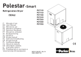
Ingersoll-Rand 200 Manual do usuário
- Categoria
- Secadoras elétricas de roupa
- Tipo
- Manual do usuário
Este manual também é adequado para

NIRVANA CYCLING REFRIGERATED DRYER
MODELS 200-400
OPERATORS MANUAL
C.C.N. : 80442775
DATE : APRIL 2007
REV. :B
Ensure that the operator reads and understands the
decals and consults the manuals before maintenance
or operation.
Ensure that the Operation and Maintenance manual is
not removed permanently from the machine.
Ensure that maintenance personnel are adequately
trained, competent and have read the Maintenance
Manuals.
a

1
Nirvana Cycling Refrigerated Dryer Models 200-400
http://air.irco.com
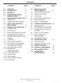
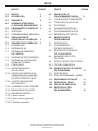
CONTENTS PAGE
1.0 CONTENTS 1
2.0 INTRODUCTION 2
3.0 WARRANTY 2
4.0 REFRIGERATED DRYER
NOMENCLATURE 2
5.0 RECEIVING AND INSPECTION 3
5.1 INSPECTION
5.2 UNPACKING AND HANDLING
6.0 SAFETY AND OPERATION
PRECAUTIONS 3
7.0 PRINCIPLES OF OPERATION 5
7.1 INTRODUCTION
7.2 AIR SYSTEM
7.3 MOISTURE REMOVAL SYSTEM
7.4 REFRIGERATION SYSTEM
7.5 THERMAL MASS CIRCULATING
SYSTEM
7.6 CONTROLS
7.6.1 BASIC USER INTERFACE
7.6.2 EXCHANGER TEMPERATURE
SET POINT AND ALARMS
7.6.3 ADJUSTING SET POINTS
7.6.4 ALARMS AND
THEIR FUNCTIONS
7.6.5 ALERT MESSAGES
7.6.6 START MODES
7.6.6.1 Manual Mode
7.6.6.2 Remote Mode (Optional)
7.6.6.3 Auto Restart
CONTENTS PAGE
8.0 INSTALLATION AND
INITIAL START-UP 8
8.1 LOCATION AND MOUNTING
8.2 PIPING AND VALVES
8.3 FILTRATION
8.4 ELECTRICAL CONNECTION
8.5 INITIAL START-UP
8.5.1 START- UP SEQUENCE
9.0 SCHEDULED MAINTENANCE 10
9.1 INTRODUCTION
9.2 REFRIGERANT CONDENSER
9.3 CONDENSATE DISCHARGE
SYSTEM
9.4 PANEL FILTER ELEMENT
9.5 PRE-FILTERS AND
POST-FILTERS
9.5.1 THREADED FILTERS
10.0 TROUBLESHOOTING 13
10.1 INTRODUCTION
10.2 PROBLEM / ACTION GUIDE
11.0 WIRING DIAGRAMS 15
12.0 GENERAL ARRANGEMENT 17
13.0 REPLACEMENT PARTS 18
14.0 ENGINEERING
SPECIFICATIONS 19
CONTENTS

Ingersoll Rand Nirvana™ Cycling refrigerated air dryer removes
moisture, oil vapor, and other contaminants from compressed air. These
contaminants are detrimental to pneumatically operated appliances,
controls, instruments, machinery and tools. This removal is
accomplished by cooling the air with a refrigeration unit to a temperature
at which moisture in the air is condensed and separated from the air
2
Nirvana Cycling Refrigerated Dryer Models 200-400
http://air.irco.com
stream. The temperature the air is cooled to, normally between 34° and
38°F (1° and 3°C), is known as dew point. This dryer can be easily
installed into various pneumatic systems in which dry air is required or
desired. Please refer to Principles of Operation for complete operating
details.
The Company warrants that the equipment manufactured by it and
delivered hereunder will be free of defects in material and workmanship
for a period of twelve months from the date of placing the Equipment in
operation or eighteen months from the date of shipment from the factory,
whichever shall first occur. The Purchaser shall be obligated to promptly
report any failure to conform to this warranty, in writing to the Company
in said period, whereupon the Company shall, at its option, correct such
nonconformity, by suitable repair to such equipment or, furnish a
replacement part F.O.B. point of shipment, provided the Purchaser has
stored, installed, maintained and operated such Equipment in
accordance with good industry practices and has complied with specific
recommendations of the Company. Accessories or equipment furnished
by the Company, but manufactured by others, shall carry whatever
warranty the manufacturers have conveyed to the Company and which
can be passed on to the Purchaser. The Company shall not be liable for
any repairs, replacements, or adjustments to the Equipment or any costs
of labor performed by the Purchaser or others without Company's prior
written approval.
The effects of corrosion, erosion and normal wear and tear are
specifically excluded. Performance warranties are limited to those
specifically stated within the Company's proposal. Unless responsibility
for meeting such performance warranties are limited to specified tests,
the Company's obligation shall be to correct in the manner and for the
period of time provided above.
THE COMPANY MAKES NO OTHER WARRANTY OR
REPRESENTATION OF ANY KIND WHATSOEVER, EXPRESSED OR
IMPLIED, EXCEPT THAT OF TITLE, AND ALL IMPLIED WARRANTIES
OF MERCHANTABILITY AND FITNESS FOR A PARTICULAR
PURPOSE, ARE HERBY DISCLAIMED.
Correction by the Company of nonconformities whether patent or latent,
in the manner and for the period of time provided above, shall constitute
fulfillment of all liabilities of the Company for such nonconformities
whether based on contract, warranty negligence, indemnity, strict liability
or otherwise with respect to or arising out of such Equipment.
The Purchaser shall not operate Equipment which is considered to be
defective, without first notifying the Company in writing of its intention to
do so. Any such use of Equipment will be at Purchaser's sole risk and
liability.
Note that this is Ingersoll Rand standard warranty. Any warranty in force
at the time of purchase of the equipment or negotiated as part of the
purchase order may take precedence over this warranty.
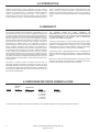
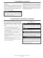
2.0 INTRODUCTION
3.0 WARRANTY
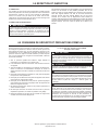
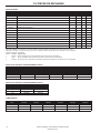
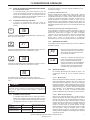
4.0 REFRIGERATED DRYER NOMENCLATURE
NOMINAL*
FLOW CONDENSER
PREFIX (SCFM) TYPE POWER RATING
NVC 200-400 A = AIR 2 = 230-1-60 0 = NEMA 1
W = WATER 4 = 460-3-60 H = NEMA 4
5 = 230-3-60
6 = 575-3-60
7 = 380-3-50
8 = 220-3-50
* Nominal Flows indicated are for 100°F inlet temperature, 100°F ambient temperature and 100 psig compressed air pressure.

3
Nirvana Cycling Refrigerated Dryer Models 200-400
http://air.irco.com
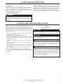
5.1 INSPECTION
Upon receiving your Ingersoll Rand air dryer, please inspect the unit
closely. If rough handling has been detected, please note it on your
delivery receipt, especially if the dryer will not be uncrated immediately.
Obtaining the delivery person’s signed agreement to any noted
damages will facilitate any insurance claims.
5.2 UNPACKING AND HANDLING
a
WARNING
Under no circumstances should any person attempt to lift heavy
objects without proper lifting equipment (i.e., crane, hoist, slings or fork
truck). Lifting any unit without proper lifting equipment, may cause
serious injury.
5.0 RECEIVING AND INSPECTION
To facilitate handling during shipment, all dryer packages have been
mounted on a base that provides for forklifting between two base
channels. Forks should extend all the way through forklift channels to
reduce unnecessary forces to the dryer during moving. Slings can be
used to lift the crates, but spreader bars must be used to prevent the
slings from exerting a force against the sides of the crates or the dryer.
6.0 SAFETY AND OPERATION PRECAUTIONS
Because an air dryer is pressurized and contains rotating parts, the
same precautions should be observed as with any piece of machinery
of this type where carelessness in operation or maintenance could be
hazardous to personnel. In addition to obvious safety rules that should
be followed with this type of machinery, safety precautions as listed
below must be observed:
1. Only qualified personnel shall be permitted to adjust, perform
maintenance or repair this air dryer.
2. Read all instructions completely before operating unit.
3. Pull main electrical disconnect switch and disconnect any separate
control lines, if used, before attempting to work or perform
maintenance on the unit.
4. Do not attempt to service any part while machine is in an operational
mode.
5. Do not attempt to remove any parts without first relieving the entire
air system of pressure.
6. Do not attempt to remove any part of the refrigeration system without
removing and containing refrigerant in accordance with the EPA and
local regulations.
7. Do not operate the dryer at pressures in excess of its rating.
8. Do not operate the dryer without guards, shields and screen in place.
9. Inspect unit daily to observe and correct any unsafe operating
conditions.
OSHA
Heading Descriptions
a
WARNING
“Warning” is used to indicate a hazardous situation which has some
probability of death or severe injury. Warning should not be considered
for property damage accidents unless personal injury risk is present.
a
CAUTION
“Caution” is used to indicate a hazardous situation which may result in
minor or moderate injury.
a
NOTICE
“Notice” is used to indicate a statement of company policy as the
message relates directly or indirectly to the safety of personnel or
protection of property. Notice should not be associated directly with a
hazard or hazardous situation and must not be used in place of
“Danger,” “Warning,” or “Caution.”
a
NOTICE
The user of any air dryer manufactured by Ingersoll Rand, is hereby
warned that failure to follow the above Safety and Operation
Precautions may result in personal injury or equipment damage.
However, Ingersoll Rand does not state as fact, nor does it mean to
imply, that the preceding list of Safety and Operating Precautions is all
inclusive, and further, that the observance of this list will prevent all
personal injury or equipment damage.

Nirvana Cycling Refrigerated Dryer Models 200-400
http://air.irco.com
4
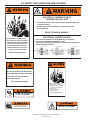
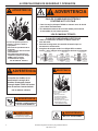
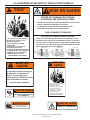
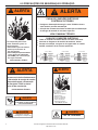
6.0 SAFETY AND OPERATION PRECAUTIONS
Air Under Pressure Will Cause
Injury, Death Or Property Damage.
• Do Not Exceed Pressure Rating.
• Relieve Press. Before Servicing.
• Do Not Modify/Repair/Rework
ASME Coded Pressure Vessels
As Insurance Rating Affected.
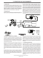
READ TECHNICAL MANUAL
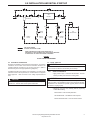
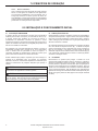
ELECTRICAL CONNECTION BOX
All Customer Connections To Be Made At This Location.
See Terminal Connection Diagrams, below.
Be Certain To Follow All NEC, State, Local and Other Applicable
Codes During Installation.
1
2
3
4
5
6
GRN
WHT
BLK
G
N
L1
FACTORY
WIRING
INCOMING
LINE VOLTAGE
100-125VAC
1PH/50-60HZ
(BY OTHERS)
(REFER TO UNIT
NAMEPLATE FOR
POWER
REQUIREMENTS)
100-125VAC / 1 PH
1
2
3
4
5
6
GRN
BLK
G
L1
RED
L2
FACTORY
WIRING
INCOMING
LINE VOLTAGE
200-240VAC
1PH/50-60HZ
(BY OTHERS)
(REFER TO UNIT
NAMEPLATE FOR
POWER
REQUIREMENTS)
200-240VAC / 1 PH
1
2
3
4
5
6
GRN
RED
WHT
G
L1
L2
BLK
L3
FACTORY
WIRING
INCOMING
LINE VOLTAGE
200-575VAC
3PH/50-60HZ
(BY OTHERS)
(REFER TO UNIT
NAMEPLATE FOR
POWER
REQUIREMENTS)
200-575VAC / 3 PH
•
•
•
ELECTRICAL CONNECTION BOX
CONTAINS HIGH VOLTAGE
• Turn Off Power And Lock Out At ALL Sources Before Opening
To Perform Service.
• Remote Alarm Contact Wiring Has Control Power From
Separate Source.
READ TECHNICAL MANUAL
Air Under Pressure Will Cause
Injury, Death Or Property Damage.
• Relieve Press. Before Servicing.
• Condensate Drain Discharges
Under Pressure.
• Drain Requires Periodic
Cleaning (Service).
READ TECHNICAL MANUAL
Removing fuses will not disconnect
power from dryer. Always disconnect
power from ALL sources before
performing service.
READ TECHNICAL MANUAL
HIGH VOLTAGE
This unit is charged with
refrigerant under high pressure.
FAN MAY AUTOMATICALLY
START AT ANY TIME
Alternate three-phase wiring may be black / black / black.

Nirvana Cycling Refrigerated Dryer Models 200-400
http://air.irco.com
5
7.1 INTRODUCTION
Ingersoll Rand Nirvana™ Cycling dryers remove moisture from
compressed air by cooling the air temperature to between 34° and 38°F
(1 and 3°C). This causes vapors to condense into liquid droplets which
can then be easily removed from the air. The major systems of the dryer
which contribute to its operation are the Air System, the Moisture
Removal System, the Refrigeration System, the Thermal Mass
Circulating System and the Controls. The following paragraphs
describe each of the systems in greater detail.
7.0 PRINCIPLES OF OPERATION
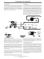
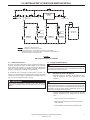
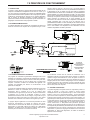
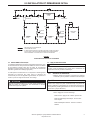
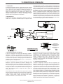
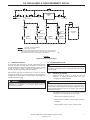
7.2 AIR SYSTEM
The air system consists of the dryer components which are in contact
with the compressed air. Referring to Figure 1 and following the bold
“
AIR FLOW
,” hot saturated air from the compressor enters the
precooler/reheater where the air temperature is reduced prior to
entering the chiller by the cool air exiting the air/moisture separator. This
precooling allows for the use of a smaller refrigeration system. The air
then goes into the chiller section where it is further cooled to the desired
dew point by a thermal mass fluid. The temperature of the thermal mass
fluid is maintained by the refrigeration circuit and controls. The air
continues to the separator where moisture is removed, thereby, allowing
the cool, dry air to return back to the precooler/reheater to be heated by
the incoming moist hot air. The air exiting the “reheater” portion of the
dryer should be approximately 15°- 20°F lower than the inlet air
temperature based on standard conditions at full rated flow.
FLOW DIAGRAM
FIGURE 1
7.3 MOISTURE REMOVAL SYSTEM
Ingersoll Rand condensate drains discharge condensed moisture and
lubricants (condensate) from compressed air equipment. The
condensate drain operates as a zero-air-loss drain, returning air that is
displaced in the drain bowl back into the compressed air system.
Consistent discharging of condensate from compressed air equipment
is essential for proper equipment operation and performance.
The condensate drain uses a unique sensing method to determine the
level of condensate in the drain bowl. A transducer located in the drain
bowl continuously sends out a signal 50 times per second. Once the
transducer determines that the level of condensate has reached a
predetermined level within the drain bowl, a signal is sent to the no-loss
drain valve to open. This operation permits removal of condensate of up
to 80 gallons per hour.
The drain also features a test button that permits manual operation of
the no-loss drain valve. Depressing the test button illuminates the LED
and energizes the solenoid valve. The LED illuminates to indicate
"POWER ON" and goes off when the no-loss drain valve is operated by
the transducer or manual test button.
The condensate flows through the feed line into the drain unit and
accumulates in the container. A capacitive sensor continuously registers
the liquid level and passes a signal to the electronic control as soon as
the container is filled. The pilot valve is then activated and the
diaphragm opens the outlet line for discharging the condensate. When
the drain unit has been emptied, the outlet line is closed again quickly
and tightly without wasting compressed air."
7.4 REFRIGERATION SYSTEM
The Refrigeration System consists of all the components which handle
R-404A. This is a hermetically sealed closed-loop system. Referring to
Figure 1 and following the phantom “
REFRIG(R-404A) FLOW,” refrigerant
is shown leaving the evaporator section where, in the process of
removing heat, it is changed from a low pressure liquid into a low
pressure gas. This gas enters the suction side of the compressor where
it is compressed into a high pressure gas. The high pressure gas is
cooled in the condenser section until it becomes a high pressure liquid.
It then goes through a permanent filter dryer that ensures the
refrigeration system is free of contaminants. A small diameter capillary
tube (expansion valve on water-cooled dryers) meters the refrigerant for
introduction into the evaporator. The refrigerant pressure is reduced
upon entering the evaporator where as it evaporates, removes heat from
the thermal mass fluid.
PROCESS AND
INSTRUMENTATION
DIAGRAM
NVC200-400
AIR AND
WATERCOOLED

6
Nirvana Cycling Refrigerated Dryer Models 200-400
http://air.irco.com
7.0 PRINCIPLES OF OPERATION
7.5 THERMAL MASS CIRCULATING SYSTEM
The thermal mass fluid in a Ingersoll Rand Nirvana™ Cycling dryer is
continuously circulated in a closed pump loop system. Referring to
Figure 1 and following the dashed “
THERMAL FLUID
” line, the heat is
removed from the fluid in the evaporator by the refrigeration system.
The thermal mass reservoir is sized to minimize refrigeration cycles
during reduced air load periods. The thermal mass fluid is pulled from
the bottom of the reservoir and pumped through the chiller, removing
heat from the air and then returned to the evaporator. The pump utilized
on the Ingersoll Rand Nirvana™ Cycling dryer is a maintenance-free,
quiet cartridge circulator pump similar to those used in residential water
systems. While the refrigeration system cycles on and off based on
loading conditions, the circulating pump runs continuously to maintain
flow through the chiller at all times. Note that when the power switch is
set to the off position, the circulating pump will not operate.
7.6 CONTROLS
The Ingersoll Rand NVC200-400 Series dryers incorporate automatic
controls for proper operation. The thermal mass fluid temperature is
maintained by a microprocessor control that monitors the temperature
and cycles the refrigeration system in response to varying air flow and
temperature. Upon an increase in the temperature of the thermal mass
fluid, the refrigeration compressor is cycled on. When the fluid is cooled
to two deg.F below its control set point, the refrigerant compressor is
cycled off. The thermal mass fluid functions as a thermal storage mass
in the NVC Series dryer.
A low pressure cut out (LPCO) switch is provided for all NVC series
dryers. This switch is factory set to open at 20 psig. If the refrigerant
suction pressure draws below 20 psig, the LPCO opens to shut off the
refrigerant compressor. Once the switch has opened, it will prevent the
compressor from running until the suction pressure rises above 60 psig
and the LPCO has been manually reset.
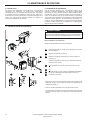
All water cooled units come with a high pressure cut out (HPCO) switch.
This switch is set to open at 320 psig and close at 270 psig. To
compensate for water temperature variation, it may be necessary to
adjust the water regulating valve to maintain a 250 psig discharge
pressure. Adjustment can be done by rotating the adjusting screw
counterclockwise for an increase in discharge pressure. For conditions
where low water temperature and/or high water pressure are expected
it is advisable to install a water pressure regulator ahead of the
condenser.
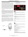
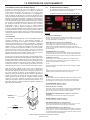
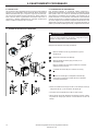
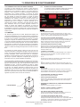
7.6.1 BASIC USER INTERFACE
The Controller provides the user with information about the
dryer’s operation and alarms.
The following illustration summarizes the keypad functions.
BUTTONS
• ON / OFF
Toggles the dryer operation between "On Line" and “Off Line” status;
Energizes glycol pump. Note that the refrigeration system will operate based
on temperature.
• EXCH SET
When depressed, will display the current exchanger set point in the LCD
window. While the exchanger set point is displayed, the up and down arrows
may be used to increase or decrease the exchanger set point temperature.
• ALARM RESET
Pressing once clears the local alarm indication and de-energizes the remote
alarm contact. Should the alarm condition persist, the alarm will return after
the alarm inhibit time has expired.
• % SAVINGS
Depressing once changes LCD display to indicate ratio of refrigeration system
running time vs. total dryer ON time.
• °F / °C
Toggles the LED temperature indicators between Fahrenheit and Celsius units
of measure.
• + / -
Allows user to modify set point values. Set point values cycle through a fixed
range.
LIGHTS
• LCD Display
Displays exchanger temperature during normal operation. Also used to
display exchanger temperature set point, alarm condition and timing functions.
• SYSTEM ENERGIZED
Indicates when power is applied to unit.
• DRYER ON
Illuminated when the On/Off switch has been pressed to place the unit in
operation. The refrigerant system may start at any time when the light is on.
• REFRIGERATION COMPRESSOR ON
Indicates that the refrigeration system is operating.
• DEGREES F / DEGREES C
Indicates the temperature units of measure.
• HIGH TEMP ALARM
Indicates that the exchanger temperature has risen to 10°F or 5°C above the
exchanger temperature set point.
• LOW TEMP ALARM
When activated, indicates that the exchanger temperature has dropped below
29°F or -2°C. This condition stops the compressor. The compressor will not
restart until the temperature has risen two degrees above exchanger set point.
ADJUSTMENT
SCREW
FIGURE 2
WATER REGULATING VALVE

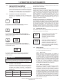
7.6.2 EXCHANGER TEMPERATURE SET POINT AND ALARMS
The Controller allows the user to configure the dryer’s
Exchanger Temperature Setpoint to operate according to site
conditions. The Controller is shipped from the factory with the
exchanger temperature having a default value of 38 deg.
7.6.3 ADJUSTING SET POINTS
Accessing and manipulating the Exchanger Temperature
Setpoint is accomplished as follows.
7
Nirvana Cycling Refrigerated Dryer Models 200-400
http://air.irco.com
7.0 PRINCIPLES OF OPERATION
The alarm names and a brief description of each are described in
detail below.
HIGH TEMPERATURE ALARM
When the thermal mass (glycol) temperature reaches the alarm set
point, the alarm will be activated. This alarm condition may not
necessarily damage the dryer when subjected to long-term exposure.
It may, however, have a significant impact on downstream processes
and thus should be investigated upon detection. Note that this alarm
will not shut down the dryer. This alarm will activate the remote alarm
contact and reset automatically once the alarm condition is rectified.
LOW TEMPERATURE SAFETY ALARM
If the dryer chiller temperature falls below the factory set point, the
alarm routine will activate. This alarm condition may cause damage to
the dryer when subjected to continuous or long-term exposure. Note
that this alarm will shut down the dryer after a response time delay.
This alarm will activate the remote alarm contact and reset
automatically once the alarm condition is rectified.
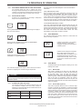
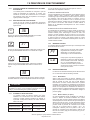
7.6.5 ALERT MESSAGES
The Controller features the following readouts to communicate the
status of the dryer’s operation.
EXCH.
SET
Pressing EXCHANGER SETPOINT button will change the display to
show the current setpoint.
36
Pressing the UP or DOWN arrows modifies the EXCHANGER
SETPOINT in one degree increment.
37
Pressing the UP or DOWN arrows modifies the EXCHANGER
SETPOINT in one degree increment.
38
The Controller accepts the last setpoint. After 5 seconds, the readout
will return to displaying the current Exchanger Temperature.
38
a
CAUTION
Do not set the Exchanger Temperature greater than 50 deg.F. Running
dryer at an Exchanger Temperature higher than 50 deg.F may damage
refrigeration system.
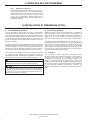
7.6.4 ALARMS AND THEIR FUNCTIONS
The Controller indicates critical alarms to alert the user of an
out of tolerance condition. Once each alarm condition is
detected, the appropriate LED indicator will illuminate and the
remote alarm contact will close.
Alarm Display Alarm Set Point
HIGH TEMPERATURE
ALARM
HI TEMP ALARM EXCH SETPOINT + 10 °F
LOW TEMPERATURE
ALARM
LOW TEMP ALARM 28 °F
Indicates a probe failure. This condition
is usually caused by a probe being
unplugged, damage to the probe lead or
a defective probe.
PF
Indicates that the refrigerant compressor
will not start until the end of a three
minute safety delay. The display of “cd” is
immediately followed by the number of
minutes left in the delay. This is a normal
function of the controller and not a fault
indication.
cd
7.6.6 START MODES
The NCV200-400 dryers are capable of starting in one of the
following start modes:
7.6.6.1 Manual Mode
After power is supplied to the dryer, the LCD display will
indicate the chiller temperature as well as the time remaining
for the safety delay. Once the delay has timed out,
depressing the On/Off button will permit the refrigeration
system to operate. Should the chiller temperature be greater
than the set point, the refrigeration system will energize.
Should the chiller temperature be below the set point, the
refrigeration system will remain off until the chiller temperature
rises to the setpoint.
7.6.6.2 Remote Mode (Optional)
This mode of operation allows the user to control the dryer
remotely and requires the installation of a customer-supplied
contact. With power applied to the dryer and once the safety
delay has timed out, the dryer will start once the remote switch
is closed. In addition, this mode of operation still permits
manual control of the dryer via the On/Off pushbutton on the
local control panel. Note that if the dryer was turned "On"
from the remote switch and then turned "Off" via the local
control panel, the remote switch must be turned "Off" and then
"On" to reinstate the dryer.

8
Nirvana Cycling Refrigerated Dryer Models 200-400
http://air.irco.com
7.0 PRINCIPLES OF OPERATION
7.6.6.3 Auto Restart
Should the dryer lose power while in the "On" mode, the dryer
will revert to the "On" mode once power is restored. Similarly,
should power be removed from the dryer while the dryer is in
the "Off" mode, the dryer will remain in the "Off" mode once
power is restored until the On/Off switch is depressed or the
remote switch is closed.
8.0 INSTALLATION AND INITIAL START-UP
8.1 LOCATION AND MOUNTING
The dryer should not be located in an area where ambient temperature
is likely to exceed 113°F (45°C) or be less than 50°F (10°C). The dryer
must be located in an area that provides sufficient clearance from walls
and other adjoining equipment to allow easy access for servicing and
maintenance requirements. A minimum of 18 inches is required to allow
free flow of air to the condenser inlet.
On installations with a relatively steady flow rate, the dryer is normally
connected after the air receiver. If loads fluctuate widely, the dryer
should be positioned ahead of the receiver and sufficient storage
capacity downstream is necessary to prevent excessive air flow through
the dryer.
When installed after any compressor that causes significant vibration or
air pulsation, such as reciprocating compressors, proper vibration
isolation and pulsation dampening devices should be added to protect
the dryer.
a
NOTICE
Failure to comply to the above instructions may result in equipment
malfunction and will void warranty.
a
NOTICE
Always use a backup wrench when making any threaded connection
to the dryer. Failure to use a backup wrench may result in damaged
tubing and components internal to the cabinet.
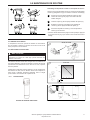
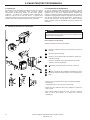
8.2 PIPING AND VALVES
Install piping, fittings and accessories as required for specific site
conditions and requirements. Figure 3 indicates a typical piping
arrangement for a refrigerated dryer, including dryer and filter bypasses.
This figure can be used as a guide for valve and accessory placement
in the system.
Ingersoll Rand NVC200-400 models come factory installed with a drain
isolation valve (D). The isolation valve permits maintenance of the
automatic drain without isolating air flow to the dryer. To operate dryer,
all valves shown in Figure 3 are to be closed except valves (B), (C) and
(D). Valve (A) is used for bypass purposes and valve (E) is for test and
manual drain purposes.
8.3 FILTRATION
To protect the air dryer from gross contamination associated with
compressor oil and debris and ensure maximum dryer performance, a
pre-filter is recommended. Pre-filters and post-filters sized to your drying
application can be provided by Ingersoll Rand and are available factory
installed. Call your local distributor to select the filter that best suits your
filtration requirements. In addition to air filtration, condensate discharge
oil/water separators are also available to address stringent EPA
regulations.

9
Nirvana Cycling Refrigerated Dryer Models 200-400
http://air.irco.com
8.0 INSTALLATION AND INITIAL START-UP
FIGURE 3
TYPICAL PIPING ARRANGEMENT
8.4 ELECTRICAL CONNECTION
Equipment is available in various electrical configurations. All customer
connections can be made at the terminal connections located in the
customer electrical connection box on the rear of the dryer. (Refer to
General Arrangement and appropriate Wiring Diagrams.)
A suitable fused disconnect switch or circuit breaker, in accordance with
national and local code requirements, is recommended for all Ingersoll
Rand equipment. Refer to Section 13 for voltage requirements and
load.
a
CAUTION
Never wire directly or connect any additional wires to the compressor
junction box. This will cause severe system malfunction.
8.5 INITIAL START-UP
a
NOTICE
For water cooled models, the water valve must be manually opened to
ensure that the condenser is full of water prior to start-up.
8.5.1 START- UP SEQUENCE
• Apply power to dryer. LCD Panel will illuminate. The Anti-
Short Cycle delay will commence counting down.
a
NOTICE
After installation or a prolonged shutdown, start the dryer with no air
load (no air flow). This enables the dryer to reach its proper operating
temperature in the shortest time possible (typically within 30 minutes
for Nirvana™ Cycling dryers).
• Start Dryer, using one of the following methods, depending
on Start Mode setting:
Manual Mode - Press the ON pushbutton.
Auto Restart Mode - No additional action required
Remote Automatic Mode - Close the remote contact.
AIR
DRYER
OIL
SEPARATOR
DRAIN
VALVE
CHECK
VALVE
CHECK
VALVE
CHECK
VALVE
DRAIN
VALVE
CHECK
VALVE
PREFILTER
B
A
C
AIR OUT
AIR IN
UNIT AS DELIVERED
OPTIONAL ACCESSORY ITEMS
NOTE:
DRAIN TUBE MUST NOT RISE OR BE CONNECTED TO
EXCESSIVELY LONG PIPE WHICH MAY CREATE BACK PRESSURE
A CONNECTION TO OPEN FLOOR DRAIN IS REQUIRED
DE
PRE-FILTER

Nirvana Cycling Refrigerated Dryer Models 200-400
http://air.irco.com
10
9.0 SCHEDULED MAINTENANCE
9.1 INTRODUCTION
Ingersoll Rand Nirvana™ Cycling refrigerated air dryers require little
maintenance. These dryers utilize hermetically sealed compressors
which do not require any lubrication. Fan motors require lubrication at
both oil ports every six months. Ingersoll Rand recommends component
inspection and service at regular intervals to obtain maximum
performance from your dryer.
9.2 REFRIGERANT CONDENSER
For standard dryers, regular inspection and cleaning of the condenser is
recommended. Ingersoll Rand dryers may be equipped with an optional
ambient air filter designed to protect the condenser from dirt and debris
that can accumulate on the condenser. For proper operation with this
option, it is imperative that this filter be inspected and cleaned on a
regular basis. Annual replacement of the filter is recommended. For
applications where excessive dirt, dust or debris is encountered, more
frequent inspection and cleaning may be required.
8
9
9
5
6
7
1
6
2
4
1
3
10
89
5
7
1
3
2
4
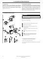
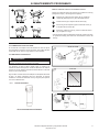
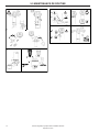
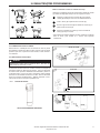
9.3 CONDENSATE DISCHARGE SYSTEM
a
WARNING
Before drain maintenance work, always close the drain isolation ball
valves and ensure that the device is pressureless and de-energized.
Maintenance recommendations
Replace service unit (5) annually.
Remove control unit (1) by pressing latching hook (2).
Detach Drain from outlet (3).
Remove design shell (4) (where applicable) using a
screw driver (10).
Remove service unit (5) from pipe at inlet by undoing
union nut
or
by undoing screws (6) at elbow connector (7)
or
by undoing screws (8) at intermediate adapter (9)
which is then detached from the service unit by
downward movement.
• Check if new service unit (5) matches control unit (1)
- type designation and colour of latching hook (2)
• Fit new service unit (5) in reverse order
• Open drain isolation ball valve. Press drain test button to verify proper
drain operation.
2
1
3
4
5
6
7

11
Nirvana Cycling Refrigerated Dryer Models 200-400
http://air.irco.com
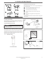
9.4 PANEL FILTER ELEMENT
Annual replacement of the panel filter element is recommended. To
replace the panel filter element, remove the panel filter by pulling up and
out of its slots, then fit the new element in.
9.5 PRE-FILTERS AND POST-FILTERS
a
WARNING
Depressurize the system before disassembling filters. Failure to do so
may result in injury or death.
Filter elements should be changed as indicated on the pressure
differential gauge. Change carbon elements when hydrocarbons are
first detected downstream or every six months, whichever comes first.
Certain filters contain multiple elements. When replacing filter elements,
all elements should be replaced simultaneously. Mixing new and old
elements can result in reduced air quality.
9.5.1 THREADED FILTERS:
NO-LOSS DRAIN VALVE
✐
GP,HE,DP 19-1380
?
2
5
4
3
2
1
6
4
3
1
Assembly Control unit onto service unit:
Check if service unit (3) matches control unit (1) (type designation and
colour of latching hook)
Check if sensor tube plate (5) with contact springs (4)
is clean, dry and free from foreign matter.
Insert sensor (2) into sensor tube plate (5).
Fit latching hook (6) of control unit (1) into sensor tube
plate (5).
Press control unit (1) against service unit (3) and snap
into place
• Open drain isolation ball valve. Press drain test button to verify proper
drain operation.
2
1
3
4
9.0 SCHEDULED MAINTENANCE
20
(68)
30
(86)
40
(104)
50
(122)
1,000
10,000
˚C
˚F
`
✐
AC19-1380
✐
hrs

12
Nirvana Cycling Refrigerated Dryer Models 200-400
http://air.irco.com
9.0 SCHEDULED MAINTENANCE
1
2
1
1
1
2
4
5
6
7
1
2
3
3
4
2
1
3a
3b
1
2
1
2
5
2
1
3
4
16mm
(5/8”)
1
✔
✘
4
✔
✘
6
7
89
1
1
3
1
2
2
2

13
Nirvana Cycling Refrigerated Dryer Models 200-400
http://air.irco.com
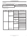
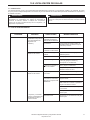
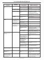
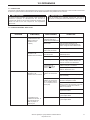
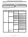
PROBLEM
Moisture down stream
Moisture down stream
SYMPTOM(S
)
Dryer is properly cooling air
stream (Check Chiller. Temp
on controller)
Inlet and outlet temperatures
are the same.
Inlet and outlet temperatures
are the same.
Compressor and fan are
running, exchanger temp
high, pump not running.
POSSIBLE CAUSE
Condensate drain failure
caused by defective service
unit.
Excessive flow
Dryer by-pass valve not
closed
No power to the dryer
High suction pressure
Refrigerant leak
Compressor not
running and
fan is running
Compressor and fan not
running.
Compressor and fan not
running. Controller indicates
compressor is ON.
Defective Pump
CORRECTIVE ACTION
Replace service unit.
Check inlet and outlet pressure and system
design capacity. Correct cause of excessive flow.
Close by-pass valve
Check power supply and fuses/circuit
breakers
Check and clean condenser.
Check suction pressure gauge if reading is
0 psig, turn dryer off and contact your
distributor
Check and clean condenser.
Check ambient temperature and reduce
below 113°F
Check Chiller Temperature
Check MAIN CONTROL fuse.
Compressor relay may be bad, replace relay
Check for loose wire connections at
contactor or loss of power at control board
Defective control board - replace as
necessary
Contact your local distributor for further
assistance.
Contact your local distributor for further
assistance.
a
WARNING
An air dryer always operates under pressure. Any maintenance
procedure that involves disassembly of pipe fittings, valves or any
other components requires the dryer be isolated from the compressed
air stream and fully depressurized.
a
WARNING
Prior to working on the unit, make sure that all circuit breakers or
disconnected switches are tagged “Out of Service.”
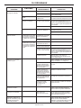
10.2 PROBLEM / ACTION GUIDE
10.0 TROUBLESHOOTING
10.1 INTRODUCTION
Ingersoll Rand Nirvana™ Cycling dryers are designed for reliable, trouble-free operation. In the event of any dryer malfunction, the guide below
has been developed to facilitate problem identification and corrective actions.

14
Nirvana Cycling Refrigerated Dryer Models 200-400
http://air.irco.com
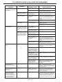
10.0 TROUBLESHOOTING
PROBLEM
Apparent controller display
malfunction
High pressure drop across
dryer
Condensate drain does not fire
Condensate drain LED is off
Air bleed from condensate
drain outlet port
Condensate drain bowl does
not seem to fill with
condensate, drain does not
seem to work due to air
locking
SYMPTOM(S
)
Display Blank
Unrealistic temperature
displayed
Erratic or inaccurate
temperature readings
Unrealistic pressure
displayed
Outlet pressure substantially
lower than inlet pressure
System operating
temperature is above 32°F
Outlet pressure substantially
lower than inlet pressure
System operating
temperature is below 32°F
POSSIBLE CAUSE
Blown Fuse
Board Failure
Probe loose,off connection or
defective probe
Probe not completely in
thermal well
Defective probe
Transducer loose, off
connection or defective
transducer
Inlet and outlet valves not
completely open
Inlet and outlet filters blocked
up
Compressor relay / contactor
stuck.
Microprocessor Control relay
bad
Probe not completely in
thermal well
Problem persists
Inlet / outlet pipe internal
diameter too small causing
air-lock or back pressure.
Excessive use of bends /
elbows in inlet / outlet pipe
work causing air-lock/ back
pressure.
Outlet pipe too long / too
high causing back pressure.
More than one condensate
source connected providing
alternative path for
condensate.
Debris trapped under seal.
Damage to seal.
CORRECTIVE ACTION
Check Fuses
Contact your local distributor for further
assistance.
Inspect probe cable and terminal connection
Replace probe
Inspect probe and check readings against
independent source (eg. temperature
analyzer/pyrometer/ice bath) both in
temperature well and to ambient
Replace probe
Inspect transducer cable and terminal
connection
Replace transducer
Open valves
Change filter elements
Replace relay / contactor.
Replace relay
Inspect probe and check readings against
independent source (eg. temperature
analyzer/pyrometer/ice bath) both in
exchanger well and to ambient
Turn dryer off and consult your local
distributor for further assistance
Check installation is in accordance with this
manual. Revise installation accordingly.
Replace with larger diameter piping.
Reduce the amount of bends and elbows.
Reconfigure condensate piping.
Reroute condensate to eliminate secondary
path. Install check valves as required.
Check power supply. Press test button for
minimum 2 seconds and observe. Locate
and eliminate supply fault.
Press and hold the test button to clear (drain
valve will open). Replace seal with Service
Kit.
If bottom inlet is used, top port must be used
as air bleed. Make sure Connect the top
inlet to a higher point in system, which will
function as an air bleed for the drain.

15
Nirvana Cycling Refrigerated Dryer Models 200-400
http://air.irco.com
WHT
RED
RED
WHT
200VAC THRU
380VAC THRU
CONNECTION
CONNECTION
DRAIN SV (SV)
CONNECTIONS
TO REMOTE ALARM BY OTHERS (OPTIONAL)
5A/120VAC MAX
REMOTE ALARM CONTACT
REMOTE START/STOP
CUSTOMER SUPPLIED
{
SWITCH
{
WARNING: DISCONNECT POWER TO DRYER
AT CUSTOMER SOURCE BEFORE SERVICING
SHOCK HAZARD: SOME CIRCUITS MAY BE
LIVE WHEN DRYER IS TURNED OFF
3
CR1
TS-3
12
WHT
PUMP (PM)
CONNECTIONS
GND
RED
WHT
GRN
5
4
TS-2
1234
YEL
RED
YEL
WHT
RED
6
DRYER ELECTRICAL COMPARTMENT FRONT PANEL
DRYER ELECTRICAL COMPONENTS
DRAIN/PUMP HOT
RED
RED
RED
RED
COMPR HOT
COMPR
ALARM HOT
PUMP/DRAIN
DRAIN TIMER
WHT RED BLK BLK
24VAC
H
POWER
N
J1
SENSORS
J4
MICROPROCESSOR BOARD
YELLOW
YELLOW
ALARM
DRYER ELECTRICAL COMPARTMENT
SHIELDED PAIR
TEMPERATURE
TO EXCHANGER
THERMOWELL
PROBE
J5
240VAC
480VAC
(TYPICAL)
HOLES IN
ELECTRICAL
COMPARTMENT
GROMMETED
* SEE NOTE 3
BLK
FAN
BLK
SEE NOTE 2.
CUT OUT SW.
HIGH PRESS
HPCO
GRN
BLK
(C1)
L1
CONTACTOR
RED
H2H1
200V
TRANSFORMER
WHT
GRN
RED
XFMR1
115V
GRN
LUG
GROUND
SIDE
THRU
480V
SIDE
H4
H3
BLK
BLK
WHT
RED
RED
RED
FU2
FU1
BLK
BLK
PRIMARY
FUSES
XFMR SECONDARY
FUSE - FU3-250V
CUT OUT SW.
RED
LOW PRESS
LPCO
GRN
GRN
RED
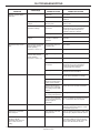
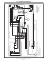
NOTES:
1. CUSTOMER POWER HOOK UP AT THE TERMINAL STRIP IN THE ELECTRICAL CONNECTION BOX IN THE
DRYER REAR ON L1, L2, L3 & GND.
2. HPCO INCLUDED WITH WATERCOOLED UNITS ONLY.
3. FAN MOTOR NOT INCLUDED ON WATERCOOLED UNITS.
4. OUTLET NOT PROVIDED ON NEMA 4 OR WEATHERPROOF OPTIONS.
5. -------- DENOTES OPTIONAL EQUIPMENT.
550037
WIRING DIAGRAM
NVC200 AIR AND WATERCOOLED
230/1/60, 220/1/50
BLK
L2
3
CONNECTIONS
CUSTOMER
TB-1
4
L3
1
2
G
L1
GRND SCREW
GRN
BLK
GRN
{
208-230 VAC/1PH/60HZ
BY OTHERS
INCOMING LINE VOLTAGE
200-220 VAC/1PH/50HZ
BLK
RED
BLK
NVC200A & W - CSR TYPE
ZEKS# 682558 EMBRACO# J9232GK BOM# 963ND
5
GROUND
4
BLK
COMP
OL
3
C
RS
WHT
RED
GND
230V/1PH/60HZ
COMPRESSOR
CONNECTIONS
1
START
RUN
4
1
COMPRESSOR
CAPACITOR
ENCLOSURE
RELAY AND
2
RED
RED
BLK
BLK
GRN
ELEC. PLUG
G
MAX LOAD 0.50 A
SEE NOTE 4
NL1
GRN
WHT
WHT
WHT
WHT
6. ALTERNATE 30 POWER LEADS MAY BE BLACK, RED, WHITE.
11.0 WIRING DIAGRAMS
WIRING DIAGRAM
NVC200 AIR AND
WATERCOOLED
230/1/60, 220/1/50

16
Nirvana Cycling Refrigerated Dryer Models 200-400
http://air.irco.com
11.0 WIRING DIAGRAMS
WHT
RED
RED
WHT
200VAC THRU
380VAC THRU
CONNECTION
CONNECTION
GRND SCREW
{
230-575 VAC/3PH/60HZ
5
DRAIN SV (SV)
BY OTHERS
CONNECTIONS
6
CUSTOMER
CONNECTIONS
TERM STRIP
TS-1
BLK
L3
INCOMING LINE VOLTAGE
200-440 VAC/3PH/50HZ
2
3
4
GRN
BLK
BLK
GRN
L2
L1
G
1
* SEE NOTE 4
575V/3PH TO 460V/3PH AUTOTRANSFORMER WIRING
575V
XFMR 1
L3
L2
X1
XFMR 2
X3
L1
X1
X3
H4
H1
X2
X4
H4
H2
H3
H3
X2
X4
H1
H2
* SEE NOTE 4
L3A
L2A
460V
L1A
WARNING: DISCONNECT POWER TO DRYER
AT CUSTOMER SOURCE BEFORE SERVICING
SHOCK HAZARD: SOME CIRCUITS MAY BE
LIVE WHEN DRYER IS TURNED OFF
3
460V/3PH CONNECTION
NOTE: REPLACE THIS BOX WITH BOX
BELOW FOR 575V/3PH POWERED UNITS
L3
L2
L1
CR1
TS-3
12
WHT
PUMP (PM)
CONNECTIONS
GND
RED
WHT
GRN
5
4
TS-2
1234
YEL
RED
YEL
WHT
RED
6
DRYER ELECTRICAL COMPARTMENT FRONT PANEL
DRYER ELECTRICAL COMPONENTS
DRAIN/PUMP HOT
RED
RED
RED
RED
COMPR HOT
COMPR
ALARM HOT
PUMP/DRAIN
DRAIN TIMER
WHT RED BLK BLK
24VAC
H
POWER
N
J1
SENSORS
J4
MICROPROCESSOR BOARD
YELLOW
YELLOW
ALARM
DRYER ELECTRICAL COMPARTMENT
SHIELDED PAIR
TEMPERATURE
TO EXCHANGER
THERMOWELL
PROBE
J5
240VAC
480VAC
200-240V/3PH/50-60HZ
2
380-480V/3PH/50-60 HZ
(TYPICAL)
HOLES IN
ELECTRICAL
COMPARTMENT
GROMMETED
BLK
1
GROUND
GRN
* SEE NOTE 3
BLK
FAN
BLK
SEE NOTE 2.
CUT OUT SW.
HIGH PRESS
HPCO
GRN
L1
BLK
COMPRESSOR
CONNECTIONS
3
(CM)
BLK
BLK
(C1)
L2 L3
CONTACTOR
RED
H2H1
200V
TRANSFORMER
GRN
RED
XFMR1
115V
GRN
LUG
GROUND
SIDE
THRU
480V
SIDE
H4
H3
BLK
BLK
RED
WHT
RED
RED
RED
RED
FU2
FU1
BLK
BLK
PRIMARY
FUSES
XFMR SECONDARY
FUSE - FU3-250V
CUT OUT SW.
RED
LOW PRESS
LPCO
GRN
GRN
MAX LOAD 0.50 A
GRN
NL1
G
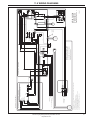
NOTES:
1. CUSTOMER POWER HOOK UP AT THE TERMINAL STRIP IN THE ELECTRICAL CONNECTION BOX IN THE
DRYER REAR ON L1, L2, L3 & GND.
2. HPCO INCLUDED WITH WATERCOOLED UNITS ONLY.
3. FAN MOTOR NOT INCLUDED ON WATERCOOLED UNITS.
4. FOR CONNECTION TO 575V/3PH SYSTEMS, SWAP BOXES ABOVE RIGHT TO INCLUDE 575V TO 460V
AUTOTRANSFORMER. NOTE: MAIN INCOMING POWER DISCONNECT AND FUSING WILL BE PROVIDED BY
CUSTOMER.
5. OUTLET NOT PROVIDED ON NEMA 4 OR WEATHERPROOF OPTIONS.
6. -------- DENOTES OPTIONAL EQUIPMENT.
550031
WIRING DIAGRAM
NVC200-400 AIR AND WATERCOOLED
208-575V/3PH/60HZ, 200-440V/3PH/50HZ
SEE NOTE 5
{
REMOTE ALARM CONTACT
TO REMOTE ALARM BY OTHERS (OPTIONAL)
5A/120VAC MAX
SWITCH
{
CUSTOMER SUPPLIED
REMOTE START/STOP
WHT
ELEC. PLUG
WHT
WHT
RED
WHT
7. ALTERNATE 30 POWER LEADS MAY BE BLACK, RED, WHITE.
WIRING DIAGRAM
NVC200-400 AIR AND WATERCOOLED
208-575V/3PH/60HZ, 200-440V/3PH/50HZ

17
Nirvana Cycling Refrigerated Dryer Models 200-400
http://air.irco.com
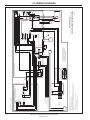
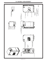
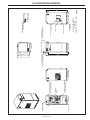
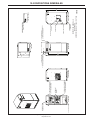
CONTROL PANEL
CONDENSATE DRAIN
STANDARD DRAIN OUTLET
LIFTING BASE WITH
FORK LIFT FEATURE
(REMOVABLE)
AIR OUTLET CONNECTION
1) 1 1/2" MPT FOR 200-250 SCFM MODELS
2) 2" FOR 300-400 SCFM MODELS
AIR INLET CONNECTION
1) 1 1/2" MPT FOR 200-250 SCFM MODELS
2) 2" FOR 300-400 SCFM MODELS
CUSTOMER ELECTRICAL
CONNECTIONS ACCESS
GLYCOL PUMP ACCESS
AMBIENT AIR FILTER LOCATION
(NOT SHOWN)
WATER COOLED INLET CONNECTION
1/2" FPT FOR 250-400 SCFM MODELS
3/8" FPT FOR 200 SCFM MODELS
WATER COOLED OUTLET CONNECTION
1/2" FPT FOR 250-400 SCFM MODELS
3/8" FPT FOR 200 SCFM MODELS
OUTFLOW VALVE
ADJUSTMENT
ACCESS
MICROPROCESSOR CONTROL
(SEE TECHNICAL MANUAL FOR
OPERATION DETAILS)
FRONT VIEWLEFT SIDE VIEW
TOP VIEW
RIGHT SIDE VIEW
25.00
30.38
23.38
2.50
57.75
55.25
REAR VIEW
32.56
550030
28.12
2.38
51.19
12.0 GENERAL ARRANGEMENT
GENERAL ARRANGEMENT
NVC200-400
AIR AND WATERCOOLED

Nirvana Cycling Refrigerated Dryer Models 200-400
http://air.irco.com
18
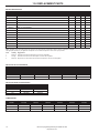
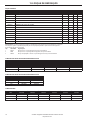
13.0 REPLACEMENT PARTS
Spare. Quantities under this heading reflect the number of each item which we recommend be kept on hand for maintenance or repair.
The appropriate quantity for your application will depend on how critical interruptions in service are to your operation.
Class Quantity Suggested for
1 Minimum Domestic service where interruptions in service are acceptable.
2 Average Domestic service where some interruptions in service are acceptable.
3 Maximum Export service or for domestic service where interruptions in service are unacceptable.
QTY/ SPARES
CCN DESCRIPTION UNIT 1 2 3
38052197 BOARD, CONTROL 1 1 1 1
38052718 CONTACTOR, COMPRESSOR 1 1 1 1
22719421 DRAIN, CONDENSATE 1
38448239 DRAIN, SERVICE UNIT 1
38052916 DRYER, REFRIGERANT FILTER 1
38052437 PANEL FILTER ELEMENT 1
38054268 FUSE, TRANSFORMER PRIMARY 2 2 2 4
38052361 FUSE, TRANSFORMER SECONDARY (EXCEPT NVC200) 1 1 1 2
38052676 OVERLAY, CONTROL BOARD 1
38052908 PROBE, EXCHANGER TEMPERATURE 1 1 1 1
38052171 SWITCH, LOW REFRIGERANT PRESSURE 1
38053252 TRANSFORMER, CONTROL - 0.15 KVA (EXCEPT NVC200) 1
38052148 VALVE, DRAIN 1
38052320 VALVE, GLYCOL PUMP ISOLATION 1
MISCELLANEOUS PARTS
PARTS FOR AIR COOLED DRYERS
FAN MOTORS
NVC NEMA 1 NEMA 4 NEMA 1 NEMA 4
MODEL CONDENSERS 230V 230V 460V 460V
200 38053104 38053229 3854789 38446498 38446498
300 38052700 38053229 3854789 38446498 38446498
400 38052700 38053229 3854789 38446498 38446498
PARTS FOR WATER COOLED DRYERS
NVC
MODEL CONDENSERS VALVES
200 38054581 38054623
300 38450029 38054631
400 38450029 38054631
COMPRESSORS
NVC
MODEL 230/1/60 230/3/60 230/3/50 380/3/50 460/3/60 575/3/60
200 38446746 38054649 38054672 38450003 38450003 38450003
300 - 38054656 38054680 38052288 38052270 38052270
400 - 38054664 38054698 38054706 38052288 38052288

19
Nirvana Cycling Refrigerated Dryer Models 200-400
http://air.irco.com
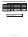
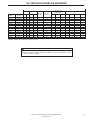
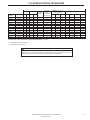
MAXIMUM ALLOWABLE WORKING PRESSURE: 230 psig
a
NOTICE
Specification information above accurate at time of publication. Refer to equipment serial label
for actual refrigerant charges and specifications for units.
14.0 ENGINEERING SPECIFICATIONS
AIR COOLED CONDENSERS
WEIGHT R-404A
MAX. FUSE
SIZE
MIN. CIRCUIT
AMPACITY
COMPRESSOR RATINGS FAN RATINGS
MODEL NO. VOLTS/PH/HZ LBS. KG. LB-OZ KG. HP RLA LRA QTY HP RLA LRA
NVC200 230/1/60 540 245 2-4 1.02 20 13.7 1 9.7 40 1 1/6 1 3
NVC200 460/3/60 540 245 2-4 1.02 6 3.9 1 2.4 13 1 1/6 0.5 1.2
NVC200 230/3/60 540 245 2-4 1.02 12 7.7 1 4.8 25 1 1/6 1 3
NVC200 575/3/60 540 245 2-4 1.02 5 3.0 1 2.4 13 1 1/6 0.5 1.2
NVC250 460/3/60 570 259 3-8 1.588 8 5.3 11/2 3.6 16 1 1/6 0.5 1.2
NVC250 230/3/60 570 259 3-8 1.588 15 9.6 11/2 6.4 38 1 1/6 1 3
NVC250 575/3/60 570 259 3-8 1.588 7 4.3 11/2 3.6 16 1 1/6 0.5 1.2
NVC300 460/3/60 630 286 4-0 1.814 10 6.2 2 4.3 16 1 1/6 0.5 1.2
NVC300 230/3/60 630 286 4-0 1.814 18 11.5 2 7.9 38 1 1/6 1 3
NVC300 575/3/60 630 286 4-0 1.814 8 4.9 2 4.3 16 1 1/6 0.5 1.2
NVC400 460/3/60 670 304 4-0 1.814 12 7.6 2 1/2 5.4 23 1 1/6 0.5 1.2
NVC400 230/3/60 670 304 4-0 1.814 25 15.9 2 1/2 11.4 57 1 1/6 1 3
NVC400 575/3/60 670 304 4-0 1.814 10 6.0 2 1/2 5.4 23 1 1/6 0.5 1.2
A página está carregando...
A página está carregando...
A página está carregando...
A página está carregando...
A página está carregando...
A página está carregando...
A página está carregando...
A página está carregando...
A página está carregando...
A página está carregando...
A página está carregando...
A página está carregando...
A página está carregando...
A página está carregando...
A página está carregando...
A página está carregando...
A página está carregando...
A página está carregando...
A página está carregando...
A página está carregando...
A página está carregando...
A página está carregando...
A página está carregando...
A página está carregando...
A página está carregando...
A página está carregando...
A página está carregando...
A página está carregando...
A página está carregando...
A página está carregando...
A página está carregando...
A página está carregando...
A página está carregando...
A página está carregando...
A página está carregando...
A página está carregando...
A página está carregando...
A página está carregando...
A página está carregando...
A página está carregando...
A página está carregando...
A página está carregando...
A página está carregando...
A página está carregando...
A página está carregando...
A página está carregando...
A página está carregando...
A página está carregando...
A página está carregando...
A página está carregando...
A página está carregando...
A página está carregando...
A página está carregando...
A página está carregando...
A página está carregando...
A página está carregando...
A página está carregando...
A página está carregando...
A página está carregando...
A página está carregando...
-
 1
1
-
 2
2
-
 3
3
-
 4
4
-
 5
5
-
 6
6
-
 7
7
-
 8
8
-
 9
9
-
 10
10
-
 11
11
-
 12
12
-
 13
13
-
 14
14
-
 15
15
-
 16
16
-
 17
17
-
 18
18
-
 19
19
-
 20
20
-
 21
21
-
 22
22
-
 23
23
-
 24
24
-
 25
25
-
 26
26
-
 27
27
-
 28
28
-
 29
29
-
 30
30
-
 31
31
-
 32
32
-
 33
33
-
 34
34
-
 35
35
-
 36
36
-
 37
37
-
 38
38
-
 39
39
-
 40
40
-
 41
41
-
 42
42
-
 43
43
-
 44
44
-
 45
45
-
 46
46
-
 47
47
-
 48
48
-
 49
49
-
 50
50
-
 51
51
-
 52
52
-
 53
53
-
 54
54
-
 55
55
-
 56
56
-
 57
57
-
 58
58
-
 59
59
-
 60
60
-
 61
61
-
 62
62
-
 63
63
-
 64
64
-
 65
65
-
 66
66
-
 67
67
-
 68
68
-
 69
69
-
 70
70
-
 71
71
-
 72
72
-
 73
73
-
 74
74
-
 75
75
-
 76
76
-
 77
77
-
 78
78
-
 79
79
-
 80
80


Ingersoll-Rand 200 Manual do usuário
- Categoria
- Secadoras elétricas de roupa
- Tipo
- Manual do usuário
- Este manual também é adequado para
em outras línguas
- español: Ingersoll-Rand 200 Manual de usuario
- français: Ingersoll-Rand 200 Manuel utilisateur
- English: Ingersoll-Rand 200 User manual
Artigos relacionados
-
Ingersoll-Rand 2000 Manual do usuário
-
-
-
-
-
-
-
-
-
Ingersoll-Rand Sierra Series Operation and Maintenance Manual
Outros documentos
-
Leupold 21 Pro Manual do usuário
-
Manitowoc Ice RN0408A Informação do produto
-
Ives S-634 Manual do usuário
-
 Parker Hiross Polestar-Smart PST350 Manual do usuário
-
GSW Chauffe-eau Polaris Manual do usuário
-
Hayward EnergyLine pro Manual do usuário
-
 Honeywell Home TH6220D1028 Guia de instalação
-
 DROPSA CannonPump Manual do proprietário
-
 World Dryer L-974 SLIMdri Surface Mounted ADA Compliant Automatic Hand Dryer Manual do usuário
-
Carrier 42VKX-AEX Manual do proprietário


