
e-mail: [email protected]
For latest product manuals:
www.omegamanual.info
TXUN-HT
2 Wire Transmitter
with Hart Protocol
TM
Shop online at
omega.com
User’s Guide

The information contained in this document is believed to be correct, but OMEGA accepts no liability for any errors it contains, and reserves
the right to alter specifications without notice.
omega.com [email protected]
Servicing North America:
U.S.A. Omega Engineering, Inc.
Headquarters: Toll-Free: 1-800-826-6342 (USA & Canada only)
Customer Service: 1-800-622-2378 (USA & Canada only)
Engineering Service: 1-800-872-9436 (USA & Canada only)
Tel: (203) 359-1660 Fax: (203) 359-7700
e-mail: [email protected]
For Other Locations Visit omega.com/worldwide

3
TXUN-HT
Table of
Contents
Table of Contents
Section ........................................................................ Page
Section 1 Application ..................................................................................... 4
Section 2 Technical Characteristics ............................................................. 5
Section 3 Application cont. ........................................................................... 6
Section 4 Ordering Codes for TXUN-HT ................................................... 7
Section 5 Technical Data ......................................................................... 8-10
Section 6 Changing the Hart protocol version .................................. 11-13
Section 6.2 Loop links ............................................................................... 12
Section 7 Connections ................................................................................. 14
Section 8 Block Diagram .............................................................................. 15
Section 9 Programming ........................................................................ 16-17
Section 10 Connection of transmitters in multidrop mode .................... 18
Section 10.1 Mechanical specifications ................................................... 18
Section 10.2 Mounting of sensor wires .................................................. 18
Section 11 Appendix ...................................................................................... 19

Application
4
1
Section 1 - 2 Wire Programmable Transmitter TXUN-HT
• RTD, TC, Ohm, or mV input
• 2 analogue inputs and 5 device variables with status
available
• HART
®
protocol revision selectable from HART
®
5
or HART
®
7
• Hardware assessed for use in SIL applications
• Mounting on a DIN rail in safe area or hazardous gas
and dust area
Application
• Linearised temperature measurement with TC and RTD sensors e.g. Pt100 and Ni100.
• HART
®
communication and 4 to 20 mA analogue PV output for individual, difference or average temperature
measurement of up to two RTD or TC
input sensors.
• Conversion of linear resistance to a standard analogue current signal, e.g from valves or Ohmic level sensors.
• Amplification of bipolar mV signals to standard 4 to 20 mA current signals.
• Up to 63 transmitters (HART
®
7) can be connected in a multidrop communication setup.

5
Technical Characteristics
2
Section 2 - Technical Characteristics
• HART® protocol revision can be changed by user configuration to either HART® 5 or HART® 7 protocol.
• The HART® 7 protocol offers:
• Long Tag numbers of up to 32 characters.
- Enhanced Burst Mode and Event notification with time stamping.
- Device variable and status mapping to any dynamic variable PV, SV, TV or QV.
- Process signal trend measurement with logs and summary data.
- Automatic event notification with time stamps.
- Command aggregation for higher communication efficiency.
• TXUN-HT is designed according to strict safety requirements and is therefore suitable for applications in SIL
installations.
• Continuous check of vital stored data.
• Meeting the NAMUR NE21 recommendations, the TXUN-HT HART® transmitter ensures top measurement
performance in harsh EMC environments. Additionally, the TXUN-HT meets NAMUR NE43 and NE89
recommendations.
Mounting / installation / programming
• For DIN form B sensor head or DIN rail mounting.
• Configuration via standard HART® communication interfaces or by TXUN-KIT.

6
Applications Cont.
3
+
-
+
-
V+
mA
V+
mA
+
-
+
-
V+
mA
+
-
+
-
V+
mA
V+
mA
+
-
+
-
+
-
+
-
+
-
+
-
+-
+-
+-
+-
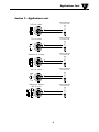
RTD to 4...20 mA
TC to 4...20 mA
Resistance to 4...20 mA
Dierence or average
RTD, TC or mV
2-wire installation
in control room
2-wire installation
in control room
2-wire installation
in control room
2-wire installation
in control room
mV to 4...20 mA
2-wire installation
in control room
Section 3 - Applications cont.

7
Ordering Codes for TXUN-HT
4
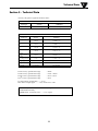
Section 4.3 - Technical data
Environmental conditions:
Specifications range ....................... -40 to 85°C
Calibration temperature ................ 20 to 28°C
Relative humidity ........................... < 95% RH (non-cond.)
Protection degree (encl./terminal) IP68/IP00
Mechanical specifications:
Dimensions .................................... Ø 44 x 20.2 mm
Weight approx. ............................... 50 g
Max. wire size ................................. 1 x1.5 mm
2
stranded wire
Screw terminal torque ................... 0.4 Nm
Vibration .......................................... IEC 60068-2-6 : 2007
2...25 Hz ........................................ ±1.6 mm
25...100 Hz .................................... ±4 g
Common electrical specifications:
Supply voltage, DC:
Standard ....................................... 8.0...35 V
ATEX, CSA, FM, IECEx & INMETRO 8.0...30 V
Voltage drop ................................... 8.0 V
Isolation - test / working .............. 1.5 kVAC / 50 VAC
Signal / noise ratio ......................... > 60 dB
Communications interface ............ Loop Link & HART
®
Response time (programmable).. . . 1...60 s
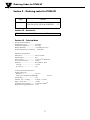
Section 4 - Ordering codes for TXUN-HT
Type Version
TXUN-HT
Standard ................ . . . . . . . . . . . . .: A
CSA, FM, ATEX, IECEx & INMETRO. . . . : D
TXUN-KIT = Loop Link USB interface and OMset Software
Section 4.2 - Accessories

8
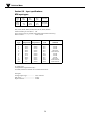
Section 5 - Technical Data
Accuracy, the greater of general and basic values:
TC
B
1
accuracy specification range > 400°C
TC
B
2
accuracy specification range > 160°C < 400°C
TC B
3
accuracy specification range > 85°C < 160°C
TC B
4
accuracy specification range < 85°C
TC cold junction compensation ... < ±1.0°C
Max. offset on input signal ........... 50% of selec. max. value
EMC immunity influence .................... < ±0.1% of span
Extended EMC immunity:
NAMUR NE 21, A criterion, burst ..... < ±1% of span
Basic values
Input type
Basic
accuracy
Temperature
coefficient
Pt50 - Pt1000
≤ ±0.1°C ≤ ±0.005°C/°C
Ni50 - Ni1000
≤ ±0.2°C ≤ ±0.005°C/°C
Lin. R
≤ ±0.1 Ω ≤ ±5 mW / °C
Volt
≤ ±10 µV ≤ ±0.5 µV / °C
TC type:
E, J, K, L, N, T, U
≤ ±0.5°C
≤ ±0.025°C / °C
TC type:
B
1
, Lr, R, S, W3, W5
≤ ±1°C
≤ ±0.1°C / °C
TC type:B
2
≤ ±3°C ≤ ±0.3°C / °C
TC type:B
3
≤ ±8°C ≤ ±0.8°C / °C
TC type:B
4
not specified not specified
General values
Input type
Absolute
accuracy
Temperature
coefficient
All ≤ ±0.05% of span ≤ ±0.005% of span / °C
Technical Data
5

9
Section 5.2 - Input specifications:
RTD input types:
RTD
type
Min.
value
Max.
values
Min.
span
Standard
Pt100
Ni100
Lin. R
-200°C
-60°C
0 W
+850°C
+250°C
7000 W
10°C
10°C
25 W
IEC 60751
DIN 43760
-----
Type
Min.
temperature
Max.
temperature
Min.
span
Standard
B
E
J
K
L
Lr
N
R
S
T
U
W3
W5
0°C
-100°C
-100°C
-180°C
-200°C
-200°C
-180°C
-50°C
-50°C
-200°C
-200°C
0°C
0°C
+1820°C
+1000°C
+1200°C
+1372°C
+900°C
+800°C
+1300°C
+1760°C
+1760°C
+400°C
+600°C
+2300°C
+2300°C
100°C
50°C
50°C
50°C
50°C
50°C
50°C
100°C
100°C
50°C
50°C
100°C
100°C
IEC584
IEC584
IEC584
IEC584
DIN 43710
GOST 3044-84
IEC584
IEC584
IEC584
IEC584
DIN 43710
ASTM E988-90
ASTM E988-90
Pt50, Pt100, Pt200, Pt500, Pt1000, Ni50, Ni100, Ni120, Ni1000
Cable resistance per wire (max.) .. 5 Ω
(up to 50 Ω per wire is possible with reduced measurement accuracy)
Sensor current ................................. Nom. 0.2 mA
TC input types:
Cold junction compensation (CJC):
Constant, internal or external via a Pt100 or Ni100 sensor
mV input:
Voltage input range ....................... -800...+800 mV
Min. span ......................................... 2.5 mV
Input resistance .............................. 10 MΩ
Technical Data
5

10
Technical Data
5
Output specifications:
Signal range..................................... 4...20 mA
Min. signal range ............................ 16 mA
Updating time ................................. 440 ms
Load resistance ............................... ≤ (V
supply
- 8) / 0.023 [Ω]
Sensor error detection, programmable 3.5...23mA
(shorted sensor error detection is ignored at TC and mV input)
NAMUR NE43 Upscale ................. 23 mA
NAMUR NE43 Downscale ........... 3.5 mA
HART
®
protocol revisions ........... HART
®
5 and HART
®
7
Approvals:
EMC 2004/108/EC ........................ EN 61326-1
EAC TR-CU 020/2011 ................... EN 61326-1
Marine approval:
Det Norske Veritas, Ships & Offshore .... Stand. for Certific. No. 2.4
Ex / I.S.:
TXUN-HT:
ATEX 94/9/EC ............................ KEMA 03ATEX1508 X
IECEx ............................................ KEM 10.0083 X
TXUN-HT:
ATEX 94/9/EC ............................ KEMA 03ATEX1537
IECEx ............................................ KEM 10.0083 X
FM ................................................. 2D5A7
CSA ............................................... 1125003
INMETRO .................................... NCC 12.0844 X
EAC Ex TR-CU 012/2011 ........... RU C-DK.GB08.V.00410
Functional Safety:
Hardware assessed for use in SIL applications

11
Changing the HART protocol Version
6
Section 6.1 - Changing the HART protocol version
Changing the HART protocol version
It is possible to change the unit's HART protocol revision by using the
OMset software and a TXUN-KIT interface or a HART interface.
Other HART configuration tools like a Handheld HART Terminal may also be used.
Procedure for using a HART hand-held terminal to change the TXUN-HT from HART 7 to HART
5 and vice versa
Change the TXUN-HT from HART 7 to HART 5:
Drive the TXUN-HT device Online and enter Device setup - Diag/Service.
Select "Write protection" and Write protect by entering " * * * * * * * * " (8 stars).
Select New password - type " * * * * * * * * " (8 stars) & then " HARTREV5 "
Select Write enable by entering " -CHANGE- ".
Change the (TXUN-HT from HART 5 to HART 7:
Drive the TXUN-HT device Online and enter Device setup - Diag/Service.
Select "Write protection" and Write protect by entering " * * * * * * * * " (8 stars).
Select New password - type " * * * * * * * * " (8 stars) & then "HARTREV7 "
Select Write enable and enter " -CHANGE- ".
Please note this is only possible if the transmitter is marked ”TXUN-HT” on the label!

12
Changing the HART protocol Version
6
Section 6.2 - Loop Link
• Loop Link is a communications interface that is needed for programming TXUN-HT.
• For programming please refer to the drawing below and the help functions in OMset.
• Loop link is not approved for communication with modules installed in harzardous (Ex) areas.
Changing the HART protocol version using the OMset software and TXUN-KIT or
a HART communication interface
Switching from HART 7 to HART 5
Select the TXUN-HT product, click the "HART" tab and open the folder ”Methods”.
Click ”Device Password / Write Protection / Protocol...” and select ”Change protocol to HART 5” in the pop-
up window, then acknowledge by pressing OK.

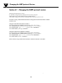
13
Changing the Hart protocol Version
6
Switching from HART 5 to HART 7
Please note this is only possible if the transmitter is marked
”TXUN-HT” on the label!
From OMset, select the TXUN-HT product, click the
”OPTIONS” tab click ”Protect”.
Write protection must be set to ”ON”. Select Change Password.
Type in the New Password ”HARTREV7” and Re-enter
”HARTREV7”. Click OK.
Switch Write protection OFF and write-enable the device
by typing in the Password ”-CHANGE-” in the top menu -
acknowledge by pressing OK.
This action will reset the password to the default active
password " * * * * * * * * " (8 stars) and restart the device in the
updated HART 7 mode with write protection disabled. Now,
select TXUN-HT in OMset and reconfigure the device.
HARTREV7
-CHANGE-

Connections
7
14
3
4
65 3
4
65 3
4
65 3
4
65
+
-
3
4
65
+
-
3
4
65
+
-
3
4
65 3
4
65
3
4
65 3
4
65
12
3
4
65
+
-
1
+
-
2
3
4
65
+
-
+
-
12
3
4
65
+
-
+
-
1 2
mA -
+
2 1
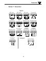
Output:
2-wire installation
Input:
Resistance, 2-wire Resistance, 3-wire
RTD, 2-wire RTD, 3-wire RTD, 4-wire
TC, internal CJC
TC, external CJC mV
Resistance, 4-wire
TC, dierence
or average,
with external CJC
mV, dierence
or average
RTD, dierence
or average
TC, dierence
or average,
with internal CJC
Section 7 - Connections

Block Diagram
8
15
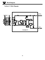
Section 8 - Block Diagram
0...16
mA
4
3
2
1
5
6
4
3
2
+
-
+
-
mV
mA
M UX
4 mA
PGA
D / A
A / D
C PU
EEPRO M
TXUN-HT
Input gnd.
Supply -
4...20 mA
TC
Ext.
CJC
mV
RTD, lin. R
- wire
Int.
CJC
Supply +
8.0...35 VDC
Comm.

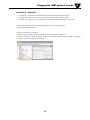
Programming
9
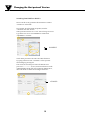
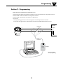
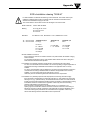
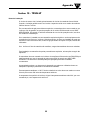
Section 9 - Programming
16
TXUN-HT can be configured in the following 3 ways:
1. With Omega TXUN-KIT communications interface Loop Link and OMset PC configuration software.
2. With a HART modem and OMset PC configuration software.
3. With a HART communicator with HART A/S’ DDL driver.
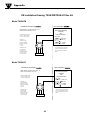
1: Loop Link
For programming please refer to the drawing below and the help functions in OMset.
Loop Link is not approved for communication with devices installed in hazardous (Ex) areas.
1
2
*
*
Loop
Link
TXUN-KIT
F
i
l
e
P
r
o
d
u
c
t
I
n
p
u
t
O
u
t
p
u
t
C
o
m
m
u
n
i
c
at
i
o
n
L
a
n
g
u
ag
e
O
p
t
i
o
n
0
8
:
3
0
:
0
0
D
at
e
:
2
0
0
4
-
8
-
1
0
0
4
3
2
0
1
5
9
4
A
n
al
o
g
i
n
p
u
t
A
n
al
o
g
o
u
t
p
u
t
S
e
r
i
al
n
o
:
I
n
p
u
t
t
yp
e
:
O
u
t
p
u
t
t
y
p
e
:
4
-
2
0
m
A
U
p
s
c
al
e
S
e
n
s
o
r
e
r
r
o
r
:
P
t
1
0
0
D
I
N
/
I
E
C
0
.
0
0
-
5
0
.
0
0
C
3
-
w
i
r
e
1
.
0
0
s
e
c
-
-
-
-
-
-
I
n
p
u
t
r
an
g
e
:
C
o
n
n
e
ct
i
o
n
:
C
o
l
d
j
u
n
c
t
i
o
n
c
o
m
p
:
R
e
s
p
o
n
se
t
i
m
e
:
T
ag
n
o
:
TXUN-HT
TXUN-HT
Omega Engineering
Disconnect
+Vsupply
* Connected only for
on-line programming
Black
Red
Yellow
Green
Input
Receiving
Equipment
Connector

17
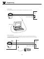
Programming
9
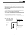
2: HART modem
For programming please refer to the drawing below and the help functions in OMset.
1
2
F
i
l
e
P
r
o
d
u
c
t
I
n
p
u
t
O
u
t
p
u
t
C
o
m
m
u
n
i
c
a
t
i
o
n
L
a
n
g
u
a
g
e
O
p
t
i
o
n
0
8
:
3
0
:
0
0
P
R
e
t
o
p
5
3
3
1
D
a
t
e
:
1
9
9
4
-
8
-
1
0
9
4
3
2
0
1
5
9
4
P
R
e
l
e
c
t
r
o
n
i
c
s
A
n
a
l
o
g
i
n
p
u
t
A
n
a
l
o
g
o
u
t
p
u
t
S
e
r
i
a
l
n
o
:
I
n
p
u
t
t
y
p
e
:
O
u
t
p
u
t
t
y
p
e
:
4
-
2
0
m
A
U
p
s
c
a
l
e
S
e
n
s
o
r
e
r
r
o
r
:
P
t
1
0
0
D
I
N
/
I
E
C
0
.
0
0
-
5
0
.
0
0
C
3
-
w
i
r
e
1
.
0
0
s
e
c
-
-
-
-
-
-
I
n
p
u
t
r
a
n
g
e
:
C
o
n
n
e
c
t
i
o
n
:
C
o
l
d
j
u
n
c
t
i
o
n
c
o
m
p
:
R
e
s
p
o
n
s
e
t
i
m
e
:
T
a
g
n
o
:
TXUN-HT
+Vsupply
Input
Receiving
Equipment
Rload > 250 W, < 1100 W
HART
®
modem
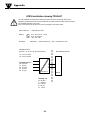
3: HART communicator
For programming please refer to the drawing below. To gain access to product-specific commands, a
suitable HART communicator must be loaded with the HART A/S DDL driver. This can be ordered at
the HART Communica tion Foundation.
1
2
TXUN-HT
Safe area
+Vsupply
Input
Receiving
Equipment
area
Rload
> 250 W, < 1100 W

18
Connection of Transmitters in Multidrop Mode
10
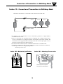
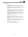
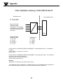
Section 10 - Connection of Transmitters in Multidrop Mode
R
A
B
C
+
-
+
-
TXUN-HT
TXUN-HT
TXUN-HT
Power
supply
Max. 63 transmitters
Rload
> 250 W, < 1100 W
The outputs of max. 63 transmitters can be connected in parallel for a digital HART
7
communication on 2-wires.
Before it is connected, each transmitter must be configured with a unique number from 1
to 63. If 2 transmitters are configured with the same number, both will be excluded. The
transmitters must be programmed for multidrop mode (with a fixed output signal of 4 mA).
Maximum current in the loop is therefore 252 mA.
The communication is either by means of a HART communicator or a HART modem.
The OMset PC configuration software can configure the individual transmitter for multidrop
mode and provide it with a unique polling address.
Mounting of sensor wires
The HART communicator or a PC modem can be connected accross AB or BC.
20.2 m m
+
-
+
-
ø 6 mm
33 mm
ø 44 mm
Wires must be mounted
between the metal plates.
Section 10.2 - Mechanical specifications
Section 10.3 - Mounting of sensor wires

Appendix
11
19
Appendix
ATEX Installation Drawing - TXUN-HT - pg20
IECEx installation drawing - TXUN-HT - pg21
FM Installation Drawing - TXUN-HT - pg 26
CSA Installation Drawing - TXUN-HT - pg 28

Appendix
11
20
5335QE01
LERBAKKEN 10, 8410 RØNDE DENMARK. WWW.PRELECTRONICS.COM
Revision date:
2014-03-31
Version Revision
V4R0
Doc. No.
5335QA02 V4R0
Page:
1/2
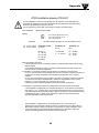
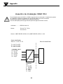
ATEX Installation drawing TXUN-HT
For safe installation of TXUN-HT the following must be observed. The module shall only
be installed by qualified personnel who are familiar with the national and international laws,
directives and standards that apply to this area.
Year of manufacture can be taken from the first two digits in the serial number.
ATEX Certificate KEMA 03ATEX 1508X
Marking
Standards EN 60079-0:2012, EN 60079-11:2012, EN 60079-15:2010
General installation instructions
If the enclosure is made of non-metallic materials or of painted metal, electrostatic charging
shall be avoided.
For an ambient temperature ≥ 60ºC, heat resistant cables shall be used with a rating of at
least 20 K above the ambient temperature.
For installation in a potentialy explosive gas atmosphere, the following instructions apply:
For “Ex ic” the transmitter must be installed in an enclosure providing a degree of protection of
at least IP20 according to EN60529 that is suitable for the app
lication and is correctly
installed.
For “Ex nA” the transmitter must be installed in an enclosure providing a degree of protection
of at least IP54 according to EN60529 that is suitable for the appli
cation and is correctly
installed, or in an enclosure with type of protection Ex n or Ex e.
Cable entry devices and blanking elements shall fulfill the same requirements.
For installation in a potentially explosive dust atmposphere, the following instructions apply:
If the transmitter is supplied with an intrinsically safe signal "ic" and interfaces an intrinsically
safe signal "ic" (e.g. a passive device), the transmitter shall be mounted in a metal enclosure
form B according to DIN 43729 that provides a degree of protection of at least IP6X according
to EN60529, and that is suitable for the application. Cable entry devices and blanking
elements shall fulfill the same requirements.
T4: -40 ≤ Ta ≤ 85ºC
T6: -40 ≤ Ta ≤ 60ºC
II 3 G Ex nA [ic] IIC T6..T4 Gc
II 3 G Ex ic IIC T6..T4 Gc
II 3 D Ex ic IIIC Dc
Terminal: 3,4,5,6
Ex nA [ic]
Uo: 9.6 V
Io: 28 mA
Po: 67 mW
Lo: 45 mH
Co: 28 μF
Terminal: 1,2
Ex nA
U ≤ 35 VDC
I = 4 - 20 mA
Terminal: 1,2
Ex ic
Ui = 35 VDC
Li = 10 μH
Ci = 1.0 nF
5335QE01
LERBAKKEN 10, 8410 RØNDE DENMARK. WWW.PRELECTRONICS.COM
Revision date:
2014-03-31
Version Revision
V4R0
Doc. No.
5335QA02 V4R0
Page:
2/2
If the transmitter is supplied with an non-sparking signal "nA", or interfaces a non
sparking signal, the transmitter shall be mounted in a metal enclosure form B according to
DIN 43729 providing a degree of protection of at least IP6X according to EN60529, and in
conformance with type of protection Ex tD and suitable for the application. Cable entry
devices and blanking elements shall fulfill the same requirements.
A página está carregando...
A página está carregando...
A página está carregando...
A página está carregando...
A página está carregando...
A página está carregando...
A página está carregando...
A página está carregando...
A página está carregando...
A página está carregando...
A página está carregando...
A página está carregando...
-
 1
1
-
 2
2
-
 3
3
-
 4
4
-
 5
5
-
 6
6
-
 7
7
-
 8
8
-
 9
9
-
 10
10
-
 11
11
-
 12
12
-
 13
13
-
 14
14
-
 15
15
-
 16
16
-
 17
17
-
 18
18
-
 19
19
-
 20
20
-
 21
21
-
 22
22
-
 23
23
-
 24
24
-
 25
25
-
 26
26
-
 27
27
-
 28
28
-
 29
29
-
 30
30
-
 31
31
-
 32
32


em outras línguas
- English: Omega TXUN-HT Owner's manual
Artigos relacionados
Outros documentos
-
PR electronics 7501 Series Manual do usuário
-
-
turck AIH401-N Guia rápido
-
Siemens 7ME4603 Installatio And User's Operating Instructions
-
-
-
Micro Motion Model D DL DT Guia de instalação
-
 Brooks 3750C Instruções de operação
-
WAGO 2-channel Analog Input for Resistance Sensors Manual do usuário
-
WIKA TIF50 tag:model:TIF52 Instruções de operação
