
e-mail: [email protected]
For latest product manuals:
www.omegamanual.info
TXUN-FD
Hart Temperature Transmitter
Field Display
TM
Shop online at
omega.com
User’s Guide

The information contained in this document is believed to be correct, but OMEGA accepts no liability for any errors it contains, and reserves
the right to alter specifications without notice.
omega.com [email protected]
Servicing North America:
U.S.A. Omega Engineering, Inc.
Headquarters: Toll-Free: 1-800-826-6342 (USA & Canada only)
Customer Service: 1-800-622-2378 (USA & Canada only)
Engineering Service: 1-800-872-9436 (USA & Canada only)
Tel: (203) 359-1660 Fax: (203) 359-7700
e-mail: [email protected]
For Other Locations Visit omega.com/worldwide

2
Section 1 Warning ............................................................................... 4
Section 2 Applications ........................................................................... 5
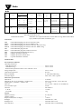
Section 3 Order .................................................................................. 6-8
Accessories .................................................................................. 6
Technical data ................................................................................ 6-8
Section 4 Block diagram ......................................................................... 9
Marking ..................................................................................... 9
Section 5 Mechanical specications ................................................................ 10-11
Section 6 Mounting .............................................................................. 12-13
Section 7 Protection degree ....................................................................... 14
Section 8 Assembly and disassembly .............................................................. 15-19
Section 9 Connections ............................................................................ 20
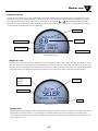
Section 10 Optical buttons ........................................................................ 21
Operating the optical buttons................................................................... 21
Display...................................................................................... 21
Section 11 Monitor View ......................................................................... 22-23
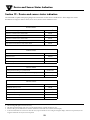
Section 12 Device and sensor status indication ...................................................... 24
Section 13 Display menu ......................................................................... 25-32
Display ...................................................................................... 28
Tags ......................................................................................... 28
Calibration................................................................................... 29
Simulation ................................................................................... 30
Sensor ....................................................................................... 31
HART ....................................................................................... 31
Write-protect ................................................................................. 32
Language .................................................................................... 32
HART Revision............................................................................... 32
Section 14 Help text overview ..................................................................... 33-34
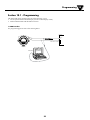
Section 15 Programming.......................................................................... 37
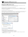
Section 16 Changing the HART protocol version .................................................... 38
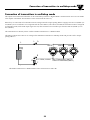
Section 17 Connection of transmitter in multidrop mode ............................................. 38
Section 18 Retrot ............................................................................... 40
Section 19 Appendix ............................................................................. 41
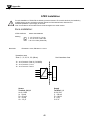
ATEX Installation Drawing .................................................................... 42
IECEx Installation Drawing .................................................................... 48
FM Installation Drawing ...................................................................... 54
CSA Installation Drawing ..................................................................... 59
Desenho de instalaçao INMETRO .............................................................. 62
Section 20 Document history...................................................................... 71
TXUN-FD
Table of
Contents

Warning
1
3
Section 1 - Warning
Only technicians, who are familiar with the technical terms, warnings, and instructions in the manual
and who are able to follow these, should connect the device.
Should there be any doubt as to the correct handling of the device, please contact Omega Engineering
Tech Support A/S.
Mounting and connection of the device should comply with national legislation for mounting of electric
materials.
Repair of the device must be done by Omega Team A/S only.
Do not remove the transmitter cover in explosive atmospheres when the circuit is live.
The transmitter cover must be fully engaged to meet the explosion proof requirements.
If installed under high-vibration conditions, the transmitter may require supplementary support.
For installation in hazardous area the corresponding installation drawing must be followed in detail.
Take care not to generate mechanical sparking when accessing the instrument and peripheral devices in
a hazardous location.

+
-
+
-
+
-
+-
+-
21
2
21
1
1
2
COMMUNICATION FOUNDATION
+
-
4
Field mounted HART temperature transmitter TXUN-FD
• RTD, TC, Ohm, and bipolar mV input and analog output
• High definition local operator interface (LOI) with 3 optical buttons
• Selectable red or white backlight
• Ex d explosion proof / flameproof in aluminum or 316 stainless steel version
• HART 7 functionality with HART 5 compatibility
High defintion display
• 0, 90, 180, & 270 degree position adjustments.
• Monitoring, programming and diagnostics view.
• Extensive diagnostics with flashing red or white backlight
• Supports 7 languages.
Local operator interface (LOI)
• 3 optical buttons; up, down and enter.
• Dynamically adaptive to wear or accumulation of dirt.
• Immune to interference from ambient light sources.
• Useable with or without gloves.
Configuration
• From the LOI through the Omega guided menu.
• OMset and HART modem.
• HHC, DCS or AMS via HART.
Mounting / installation
• For installation in zone 0, 1, 2 and zone 20, 21, 22,and in
Class 1, Division 1 and 2 applications.
• Hardware assessed for use in SIL 2 applications.
• Mounting on 1.5”–2” pipe bracket or on wall / bulkhead.
Application
• Linearized temperature measurement with TC and RTD
sensors e.g. Pt100 and Ni100.
• HART communication and 4...20 mA analog PV output for
individual, difference or average temperature
measurement of up to two RTD or TC input sensors.
• Conversion of linear resistance to a standard analog
current signal, e.g from valves or Ohmic level sensors.
• Amplification of bipolar mV signals to standard 4...20 mA
current signals.
• Up to 63 transmitters (HART 7) can be connected in a
multidrop communication setup.
Technical characteristics
• NAMUR NE43 and NE89.
• HART protocol revision can be changed by user
configuration to either HART 5 or HART 7 protocol.
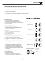
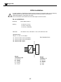
Section 2.1 - Applications
Input signals:
TC to 4...20 mA
Ex ia: 10...30 VDC
(12...30 VDC with back-
light)
Other: 10...35 VDC
(12...35 VDC with back-
light)
4...20 mA
Resistance to 4...20 mA
mV to 4...20 mA
Difference or average
RTD, TC or mV
2-wire output and HART:
RTD to 4...20 mA
Application
2

Order
3
5
Accessories
8550 = TXUN-FD M20 plug text alu encl. silicone O-ring
8550-F = TXUN-FD M20 plug text alu encl. FKM O-ring
8550-S = TXUN-FD M20 plug text stainless steel encl. silicone O-ring
8550-SF = TXUN-FD M20 plug text stainless steel encl. FKM O-ring
8551 = TXUN-FD NPT plug alu encl.
8551-S = TXUN-FD NPT plug text stainless steel encl.
8552 = Pipe-mounting bracket P5-B-N (1½”-2”)
8555 = Display spare part with LOI
8556 = Display spare part without LOI
1117 = 5-point calibration certificate
Technical data
Environmental conditions:
Operating tempeature
with silicone O-ring . . . . . . . . . . . . . . . . . . . . . . . . . . . . . . -40°C to +85°C
with FKM O-ring . . . . . . . . . . . . . . . . . . . . . . . . . . . . . . . . -20°C to +85°C
Reduced LCD performance below -20°C and above +70°C
Storage temperature . . . . . . . . . . . . . . . . . . . . . . . . . . . . . . . -40°C to +85°C
Calibration temperature . . . . . . . . . . . . . . . . . . . . . . . . . . . . . 20...28°C
Relative humidity. . . . . . . . . . . . . . . . . . . . . . . . . . . . . . . . . 0...100% RH (condensing)
Protection degree . . . . . . . . . . . . . . . . . . . . . . . . . . . . . . . . . IP54 / IP66 / IP68 / type 4X
Mechanical specifications:
Dimensions . . . . . . . . . . . . . . . . . . . . . . . . . . . . . . . . . . . . Ø 110 mm
Dimensions, H x W x D, aluminum / stainless steel . . . . . . . . . . . . . 109.3 x 145 x 126 mm / 107.4 x 145 x 124
Weight approx., aluminum / stainless steel . . . . . . . . . . . . . . . . . . 1.3 / 2.8 kg
Wire size . . . . . . . . . . . . . . . . . . . . . . . . . . . . . . . . . . . . . . 0.13...1.5 mm
2
/ AWG 26...16 stranded wire
Screw terminal torque . . . . . . . . . . . . . . . . . . . . . . . . . . . . . . 0.4 Nm
Vibration. . . . . . . . . . . . . . . . . . . . . . . . . . . . . . . . . . . . . . IEC 60068-2-6
2...25 Hz . . . . . . . . . . . . . . . . . . . . . . . . . . . . . . . . . . . . . ±1.6 mm
25...100 Hz. . . . . . . . . . . . . . . . . . . . . . . . . . . . . . . . . . . . ±4 g
Display:
Display resolution . . . . . . . . . . . . . . . . . . . . . . . . . . . . . . . . 96 x 64 pixels
Number of digits . . . . . . . . . . . . . . . . . . . . . . . . . . . . . . . . . 5
Response time, button to display . . . . . . . . . . . . . . . . . . . . . . . . < 150 ms
Backlight. . . . . . . . . . . . . . . . . . . . . . . . . . . . . . . . . . . . . . Selectable ON / OFF
Backlight color . . . . . . . . . . . . . . . . . . . . . . . . . . . . . . . . . . Selectable white or red
Error indication . . . . . . . . . . . . . . . . . . . . . . . . . . . . . . . . . . Selectablewhiteorred(ashing)
Order
Examples: TXUN-FDA1B1A22 = Aluminum, blind cover, FKM rubber O-ring, M20x1.5 6H conduit, epoxy, connection kit,
hazardous installation, red
TXUN-FDA3A1A12GY = Aluminum, Local Operator Interface, silicone rubber O-ring, M20x1.5 6H conduit,
epoxy, HART TT, hazardous installation, gray
Type Housing
Local operator
interface
O-ring
Conduit
thread
(D1, D2 & D3)
Paint
type
Transmitter Approvals
Cover color
Optical
buttons
Display
TXUN-
FD
Low copper
aluminum (AL)
: A No
No
Yes
No
Yes
Yes
: 1
: 2
: 3
-40 to +85°C
silicone rubber
-20 to +85°C
FKM rubber
: A
: B
M20x1.5 6H : 1
½ NPT mod. : 2
Epoxy : A
Epoxy + poly-
urethane : B
Yes
No (comes with
a connection kit)
: 1
: 2
General
purpose: 1
Hazardous area: 2
Red: -
Yes Yes : 3 Yes : 1 Hazardous area: 2 Gray: GY
TXUN-
FD
316 Stainless
steel (RF)
: B No
Yes
Yes
Yes
: 2
: 3
-40 to +85°C
silicone rubber
-20 to +85°C
FKM rubber
: A
: B
M20x1.5 6H : 1
½ NPT mod. : 2
None : N Yes
No (comes with
a connection kit)
: 1
: 2
General purpose: 1
Hazardous area: 2
Steel: -

6
Common electrical specifications:
Supply voltage, DC:
Ex ia, intrinsically safe . . . . . . . . . . . . . . . . . . . . . . . . . . . . . 10...30 VDC
(12...30 VDC with backlight)
Other . . . . . . . . . . . . . . . . . . . . . . . . . . . . . . . . . . . . . . . 10...35 VDC
(12...35 VDC with backlight)
Isolation - test / working . . . . . . . . . . . . . . . . . . . . . . . . . . . . 1.5 kVAC / 50 VAC
Signal / noise ratio . . . . . . . . . . . . . . . . . . . . . . . . . . . . . . . . > 60 dB
Programming . . . . . . . . . . . . . . . . . . . . . . . . . . . . . . . . . . . HART
Start-up time (transmitter to display) . . . . . . . . . . . . . . . . . . . . . Max. 5 s
Response time (programmable). . . . . . . . . . . . . . . . . . . . . . . . . . 1...60 s
Long term stability . . . . . . . . . . . . . . . . . . . . . . . . . . . . . . . . 0.1% of span / year
Accuracy, the greater of general and basic values:
TC B
1
accuracyspecicationrange . . . . . . . . . . . . . . . . . . . . . . . > 400°C
TC B
2
accuracyspecicationrange . . . . . . . . . . . . . . . . . . . . . . . > 160°C < 400°C
TC B
3
accuracyspecicationrange . . . . . . . . . . . . . . . . . . . . . . . > 85°C < 160°C
TC B
4
accuracyspecicationrange . . . . . . . . . . . . . . . . . . . . . . . < 85°C
TC cold junction compensation . . . . . . . . . . . . . . . . . . . . . . . . . < ±1.0°C
Max.osetoninputsignal . . . . . . . . . . . . . . . . . . . . . . . . . . . 50% of selec. max. value
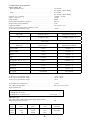
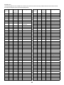
Input specifications:
RTD input types:
Pt50, Pt100, Pt200, Pt500, Pt1000, Ni50, Ni100, Ni120, Ni1000
Cable resistance per wire (max.) . . . . . . . . . . . . . . . . . . . . . . . . 5Ω
RTD
type
Min.
value
Max.
value
Min.
span
Standard
Pt100
Ni100
Lin. R
-200°C
-60°C
0Ω
+850°C
+250°C
7000Ω
10°C
10°C
25Ω
IEC 60751
DIN 43760
-----
EMC-immunityinuence . . . . . . . . . . . . . . . . . . . . . < ±0.1% of span
Extended EMC immunity:
NAMUR NE 21, A criterion, burst . . . . . . . . . . . . . . . . . < ±1% of span
General values
Input type Absolute accuracy Temperaturecoecient
All ≤±0.05%ofspan ≤±0.005%ofspan/°C
Basic values
Input type Basic accuracy Temperaturecoecient
Pt50 - Pt1000 ≤±0.1°C ≤±0.005°C/°C
Ni50 - Ni1000 ≤±0.2°C ≤±0.005°C/°C
Lin. R ≤±0.1Ω ≤±5mΩ/°C
Volt ≤±10μV ≤±0.5µV/°C
TC type: E, J, K, L, N, T, U ≤±0.5°C ≤±0.025°C/°C
TC type: B
1
, Lr, R, S, W3, W5 ≤±1°C ≤±0.1°C/°C
TC type:B
2
≤±3°C ≤±0.3°C/°C
TC type:B
3
≤±8°C ≤±0.8°C/°C
TC type:B
4
notspecied notspecied

7
(upto50Ωperwireispossiblewithreducedmeasurementaccuracy)
Sensor current. . . . . . . . . . . . . . . . . . . . . . . . . . . . . . . . . . . Nom. 0.2 mA
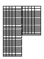
TC input types:
Cold junction compensation (CJC): Constant, internal or external via a Pt100 or Ni100 sensor
mV input:
Voltage input range. . . . . . . . . . . . . . . . . . . . . . . . . . . . . . . . -800...+800 mV
Min. span . . . . . . . . . . . . . . . . . . . . . . . . . . . . . . . . . . . . . 2.5 mV
Input resistance . . . . . . . . . . . . . . . . . . . . . . . . . . . . . . . . . . 10MΩ
Output specifications:
Signal range . . . . . . . . . . . . . . . . . . . . . . . . . . . . . . . . . . . . 4...20 mA
Min. signal range . . . . . . . . . . . . . . . . . . . . . . . . . . . . . . . . . 16 mA
Updating time. . . . . . . . . . . . . . . . . . . . . . . . . . . . . . . . . . . 440 ms
Load resistance . . . . . . . . . . . . . . . . . . . . . . . . . . . . . . . . . . ≤(Vsupply-10)/0.023[Ω]
with backlight. . . . . . . . . . . . . . . . . . . . . . . . . . . . . . . . . . ≤(Vsupply-12)/0.023[Ω]
Sensor error detection, programmable . . . . . . . . . . . . . . . . . . . . . 3.5...23 mA
(shorted sensor error detection is ignored at TC and mV input)
NAMUR NE43 Upscale . . . . . . . . . . . . . . . . . . . . . . . . . . . . . 23 mA
NAMUR NE43 Downscale . . . . . . . . . . . . . . . . . . . . . . . . . . . 3.5 mA
HART protocol revisions. . . . . . . . . . . . . . . . . . . . . . . . . . . . . HART 7 and HART 5
Marine approval:
EU RO Mutual Recognition Type Approval . . . . . . . . . . . . . . . . . . MRA0000009
Ex approvals:
ATEX 2014/34/EU . . . . . . . . . . . . . . . . . . . . . . . . . . . . . . . . DEKRA 15 ATEX 0058 X
IECEx . . . . . . . . . . . . . . . . . . . . . . . . . . . . . . . . . . . . . . . IECEx DEK 15.0039 X
cFMus . . . . . . . . . . . . . . . . . . . . . . . . . . . . . . . . . . . . . . . FM16US0009X / FM16CA0010X
cCSAus. . . . . . . . . . . . . . . . . . . . . . . . . . . . . . . . . . . . . . . 70024231
INMETRO . . . . . . . . . . . . . . . . . . . . . . . . . . . . . . . . . . . . . DEKRA 15.0014 X
NEPSI . . . . . . . . . . . . . . . . . . . . . . . . . . . . . . . . . . . . . . . GYJ15.1336X, GYJ15.1337X and
GYJ15.1338X
EAC Ex TR-CU 012/2011 . . . . . . . . . . . . . . . . . . . . . . . . . . . . RU C-DK.GB08.V.01316
Observed authority requirements:
EMC . . . . . . . . . . . . . . . . . . . . . . . . . . . . . . . . . . . . . . . . 2014/30/EU
RoHS . . . . . . . . . . . . . . . . . . . . . . . . . . . . . . . . . . . . . . . . 2011/65/EU
EAC . . . . . . . . . . . . . . . . . . . . . . . . . . . . . . . . . . . . . . . . TR-CU 020/2011
Functional Safety:
Hardware assessed for use in SIL 2 applications
Type
Min.
temperature
Max.
temperature
Min.
span
Standard
B
E
J
K
L
Lr
N
R
S
T
U
W3
W5
0°C
-100°C
-100°C
-180°C
-200°C
-200°C
-180°C
-50°C
-50°C
-200°C
-200°C
0°C
0°C
+1820°C
+1000°C
+1200°C
+1372°C
+900°C
+800°C
+1300°C
+1760°C
+1760°C
+400°C
+600°C
+2300°C
+2300°C
100°C
50°C
50°C
50°C
50°C
50°C
50°C
100°C
100°C
50°C
50°C
100°C
100°C
IEC584
IEC584
IEC584
IEC584
DIN 43710
GOST 3044-84
IEC584
IEC584
IEC584
IEC584
DIN 43710
ASTM E988-90
ASTM E988-90
Order
3

8
T1
T2
T3
T4
T5
T6
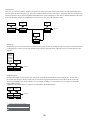
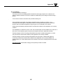
TXUN-FD
HART
HART
Application
Sensor
UP DOWN ENTER
HART
slave
HART
“master”
HART
modem
Filter
HART
modem
Supply
Display
TXUN-HT
HART
transmitter
4...20 mA
+ HART
4...20 mA
+ HART
8 V / 4...20 mA
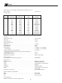
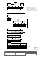
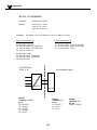
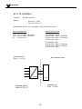
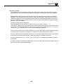
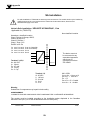
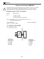
Block Diagram
4
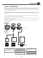
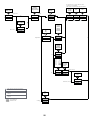
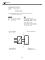
Section 4.1 - Block diagram
Caution
The ambient temperature range depends on T rating, type of protection and sealing materials, see the installation drawing.

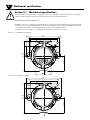
145
127
65
AL: 126
RF: 124
114
64,50
40
D1
D2
D3
145
127
114
64,50
40
D1
D2
D3
AL: 126
RF: 124
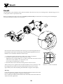
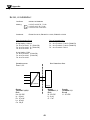
Mechanical specifications
5
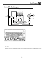
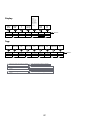
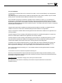
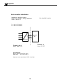
Front view – with buttons and display
Front view – no buttons or display
9
Section 5.1 - Mechanical specifications
It is important to be careful when screwing the cover on or off. The thread surface must be free of any grains,
pellets or other impurities as these can cause the cover to seize or damage the threads.
! Never use force to screw on the cover.
Should it be necessary to open the connection head cover after operation in maximum temperature, please be
aware that the cover may be blocked (does not give when attempting to open it by hand). In this case, keep the
cover under tension with your hand and hit the cover gently with a rubber hammer.
All dimensions below in mm. AL = aluminum version and RF = stainless steel version.

AL: 7
RF: 6
AL: 109.3
RF: 107.4
AL: 35
RF: 34
AL: 25 / RF: 24
10
Mechanical specifications
5

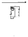
2 x Ø 7
127
Front view – with buttons and display
Front view – no buttons or display
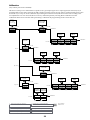
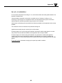
Mounting
6
11

M6
51
19
98
D = 1½" - 2"
Pipe-mounting – front and back view
Pipe-mounting – top view
12
Mounting
6

Protection Degree
7
13
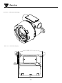
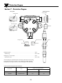
D1
D2
D3
Sealing washer
Threaded sealant
Sealing washer
Threaded sealant
Threaded sealant
SensorSealing washer
Blanking elements
Cable glands
20 x 1.5
½ NPTmod
½ NPTmod
20 x 1.5
Section 7 - Protection Degree
Blind plug M20 . . . . . . . . . . . . . . . . . . . . . . . . . . . . . . . . . . IP54
With O-ring . . . . . . . . . . . . . . . . . . . . . . . . . . . . . . . . . . . IP66 - IP68
Blind plug ½” NPT MOD . . . . . . . . . . . . . . . . . . . . . . . . . . . . IP54
With locktite 577 . . . . . . . . . . . . . . . . . . . . . . . . . . . . . . . . IP66 - IP68
ProtectiondegreeisdenedbytheconnectionwiththelowestIPrating.
It is optional to connect a sensor to any of the three conduit openings.
Blind plugs are Ex approved only when used together with TXUN-FD.
Earth terminal and protection terminal
Placement Type
Cablecrosssection[mm
2
]
Stranded wire Solid wire
Inside Protection terminal 1.5 2.5
Outside Earth terminal 4.0 6.0

A-F = 2mm
1 2
3 3
14
Locking screw
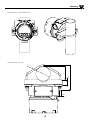
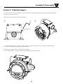
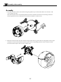
Assembly & Disassembly
8
To connect sensor wires to the TXUN-FD or change the orientation of the display, the housing must be disassembled and the
internal device must be extracted.
!! Disconnect power to the device before disassembly.
1. Releasethelockingscrew,usingahexspannerwithacross-flatof2[mm].Thisscrewissituatedonthehousingtop.
2. Unscrew the housing lid by turning it counterclockwise.
Point 3 and 4 only apply to devices with buttons and display.
3. Press and hold the two clamps located on the left and right side of the display unit.
Section 8 - Protection Degree

a a
b b
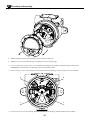
4. While holding the clamps, pull the display unit outwards to remove it.
5. The display can now be turned in steps of 90 degrees for best viewing angle.
6. For easy connection of sensor wires, we recommend extracting the transmitter from the housing (see the section
Connections for information on connecting sensors to the internal 5337).
7. Unscrew the two screws (a) fastening the connector bracket to the housing, using a Posidriv form Z screwdriver.
8. Unscrew the two screws (b) fastening the fixation bracket to the housing, and pull out the entire assembly.
15
Assembly & Disassembly
8

9. Use a screwdriver (or your fingers) to lever the taps (one on each side) on the fixation bracket to release it from the
transmitter connector bracket.
NB! Do not use excessive force.
10. Separate the connector bracket, transmitter and fixation bracket.
16
Assembly & Disassembly
8

RF
Al
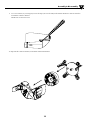
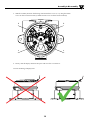
Assembly
1. Place the transmitter in the fixation bracket using the guidance taps on the bracket. Make sure terminals 1 and
2 are facing downwards.
NB. The fixation bracket is not interchangeable between the aluminum and stainless steel housing. Check the
bottom right-hand corner for identifier (Al for aluminum and RF for stainless steel).
2. Slide the connector bracket onto the transmitter using the dovetails as guides. Make sure the golden connector pins
on terminal 1 and 2 on the transmitter slide into place in the corresponding terminals on the connector bracket.
Press the bracket into place until you hear a distinct click.
17
Assembly & Disassembly
8

a a
b b
4. Finally, click the display unit back into place and screw the cover back on.
Correct mounting of display unit
18
3. Slide the assembly back into the housing and refasten the 4 screws (a + b), using the 28 mm
screws for the connector bracket (a) and the 10 mm screws for the fixation bracket (b).
Assembly & Disassembly
8

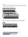
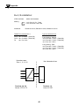
Connections
9
19
+
-
12
+
-
1
+
-
2
+
-
+
-
12
+
-
+
-
2 1
3
4
6
5
+
-
3
4
6
5
3
4
6
5
+
-
3
4
6
5
3
4
6
5
3
4
6
5
3
4
6
5
3
4
6
5
3
4
6
5
3
4
6
5
3
4
6
5
3
4
6
5
3
4
6
5
-
+
12
m
A
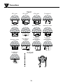
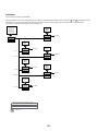
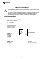
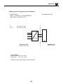
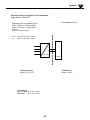
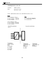
Output:
Input:
Resistance, 2-wire
Resistance, 3-wire
RTD, 2-wire RTD, 3-wire RTD, 4-wire
TC, internal CJC
TC, external CJC mV
Resistance, 4-wire
TC, dierence
or average,
with external CJC
mV, dierence
or average
RTD, dierence
or average
TC, dierence
or average,
with internal CJC
A página está carregando...
A página está carregando...
A página está carregando...
A página está carregando...
A página está carregando...
A página está carregando...
A página está carregando...
A página está carregando...
A página está carregando...
A página está carregando...
A página está carregando...
A página está carregando...
A página está carregando...
A página está carregando...
A página está carregando...
A página está carregando...
A página está carregando...
A página está carregando...
A página está carregando...
A página está carregando...
A página está carregando...
A página está carregando...
A página está carregando...
A página está carregando...
A página está carregando...
A página está carregando...
A página está carregando...
A página está carregando...
A página está carregando...
A página está carregando...
A página está carregando...
A página está carregando...
A página está carregando...
A página está carregando...
A página está carregando...
A página está carregando...
A página está carregando...
A página está carregando...
A página está carregando...
A página está carregando...
A página está carregando...
A página está carregando...
A página está carregando...
A página está carregando...
A página está carregando...
A página está carregando...
A página está carregando...
A página está carregando...
A página está carregando...
A página está carregando...
A página está carregando...
A página está carregando...
A página está carregando...
-
 1
1
-
 2
2
-
 3
3
-
 4
4
-
 5
5
-
 6
6
-
 7
7
-
 8
8
-
 9
9
-
 10
10
-
 11
11
-
 12
12
-
 13
13
-
 14
14
-
 15
15
-
 16
16
-
 17
17
-
 18
18
-
 19
19
-
 20
20
-
 21
21
-
 22
22
-
 23
23
-
 24
24
-
 25
25
-
 26
26
-
 27
27
-
 28
28
-
 29
29
-
 30
30
-
 31
31
-
 32
32
-
 33
33
-
 34
34
-
 35
35
-
 36
36
-
 37
37
-
 38
38
-
 39
39
-
 40
40
-
 41
41
-
 42
42
-
 43
43
-
 44
44
-
 45
45
-
 46
46
-
 47
47
-
 48
48
-
 49
49
-
 50
50
-
 51
51
-
 52
52
-
 53
53
-
 54
54
-
 55
55
-
 56
56
-
 57
57
-
 58
58
-
 59
59
-
 60
60
-
 61
61
-
 62
62
-
 63
63
-
 64
64
-
 65
65
-
 66
66
-
 67
67
-
 68
68
-
 69
69
-
 70
70
-
 71
71
-
 72
72
-
 73
73


em outras línguas
- English: Omega TXUN-FD Owner's manual
Artigos relacionados
Outros documentos
-
PR electronics 7501 Series Manual do usuário
-
-
Mitsubishi Heavy Industries eco touch RC-EX1N Guia de instalação
-
Videotec MAXIMUS MPXR SERIES2 Manual do usuário
-
Snap-On ControlTech Micro Calibration Procedure
-
Videotec MAXIMUS MMX Manual do usuário
-
Siemens 7ME4603 Installatio And User's Operating Instructions
-
WIKA TIF50 tag:model:TIF52 Instruções de operação
-
turck AIH401-N Guia rápido
-