PR electronics 7501 Series Manual do usuário
- Tipo
- Manual do usuário

PERFO RMANCE
MADE
SMARTER
Product Manual
7501
Field mounted HART
temperature transmitter
TEMPERATURE | I.S. INTERFACES | COMMUNICATION INTERFACES | MULTIFUNCTIONAL | ISOLATION | DISPLAY
No. 7501V107-UK
Serial no.: 170807001-170816075

6 Product Pillars
to meet your every need
With our innovative, patented technologies, we make signal conditioning smarter and simpler. Our portfolio is composed of six
product areas, where we offer a wide range of analog and digital devices covering over a thousand applications in industrial
and factory automation. All our products comply with or surpass the highest industry standards, ensuring reliability in even
the harshest of environments and have a 5-year warranty for greater peace of mind.
Individually outstanding, unrivalled in combination
Our range of temperature transmitters and sensors provides the highest level of signal integrity from the
measurement point to your control system. You can convert industrial process temperature signals to analog, bus or
digital communications using a highly reliable point-to-point solution with a fast response time, automatic self-
calibration, sensor error detection, low drift, and top EMC performance in any environment.
Our unique range of single devices covering multiple applications is easily deployable as your site standard. Having
one variant that applies to a broad range of applications can reduce your installation time and training, and greatly
simplify spare parts management at your facilities. Our devices are designed for long-term signal accuracy, low
power consumption, immunity to electrical noise and simple programming.
We provide inexpensive, easy-to-use, future-ready communication interfaces that can access your PR installed base
of products. The detachable 4501 Local Operator Interface (LOI) allows for local monitoring of process values,
device configuration, error detection and signal simulation. The next generation, our 4511 Remote Operator
Interface (ROI) does all that and more, adding remote digital communications via Modbus/RTU, while the analog
output signals are still available for redundancy.
With the 4511 you can further expand connectivity with a PR gateway, which connects via industrial Ethernet,
wirelessly through a Wi-Fi router or directly with the devices using our Portable Plant Supervisor (PPS) application.
The PPS app is available for iOS, Android and Windows.
Our display range is characterized by its flexibility and stability. The devices meet nearly every demand for display
readout of process signals, and have universal input and power supply capabilities. They provide a real-time
measurement of your process value no matter the industry, and are engineered to provide a user-friendly and
reliable relay of information, even in demanding environments.
We deliver the safest signals by validating our products against the toughest safety standards. Through our
commitment to innovation, we have made pioneering achievements in developing I.S. interfaces with SIL 2 Full
Assessment that are both efficient and cost-effective. Our comprehensive range of analog and digital intrinsically
safe isolation barriers offers multifunctional inputs and outputs, making PR an easy-to-implement site standard.
Our backplanes further simplify large installations and provide seamless integration to standard DCS systems.
Our compact, fast, high-quality 6 mm isolators are based on microprocessor technology to provide exceptional
performance and EMC-immunity for dedicated applications at a very low total cost of ownership. They can be
stacked both vertically and horizontally with no air gap separation between units required.

7501V107-UK 3
Field mounted HART
temperature transmitter
7501
Table of contents
Warning ................................................................................................ 4
Applications ............................................................................................ 5
Order ................................................................................................... 6
Accessories ............................................................................................. 6
Technical data .......................................................................................... 6
Block diagram .......................................................................................... 9
Marking................................................................................................. 9
Mechanical specifications ................................................................................ 10
Mounting ............................................................................................... 12
Protection degree . . . . . . . . . . . . . . . . . . . . . . . . . . . . . . . . . . . . . . . . . . . . . . . . . . . . . . . . . . . . . . . . . . . . . . . . . . . . . . . . . . . . . . . 14
Assembly and disassembly .............................................................................. 15
Connections ............................................................................................ 20
Optical buttons.......................................................................................... 21
Operating the optical buttons ............................................................................ 21
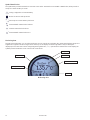
Display ................................................................................................. 21
Device and sensor status indication ...................................................................... 24
Display menu ........................................................................................... 25
Display .............................................................................................. 28
Tags................................................................................................. 28
Calibration ........................................................................................... 29
Simulation ........................................................................................... 30
Sensor .............................................................................................. 31
HART................................................................................................ 31
Write-protect ........................................................................................ 32
Language............................................................................................ 32
HART Revision ....................................................................................... 32
Help text overview ...................................................................................... 33
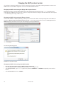
Programming ........................................................................................... 37
Changing the HART protocol version ...................................................................... 38
Retrofit................................................................................................. 40
Appendix . . . . . . . . . . . . . . . . . . . . . . . . . . . . . . . . . . . . . . . . . . . . . . . . . . . . . . . . . . . . . . . . . . . . . . . . . . . . . . . . . . . . . . . . . . . . . . . 41
ATEX Installation Drawing ............................................................................ 42
IECEx Installation Drawing ............................................................................ 48
FM Installation Drawing............................................................................... 54
CSA Installation Drawing.............................................................................. 59
Desenho de instalaçao INMETRO ...................................................................... 62
Document history ....................................................................................... 68

4 7501V107-UK
Warning
Only technicians, who are familiar with the technical terms, warnings, and instructions in the manual and
who are able to follow these, should connect the device.
Should there be any doubt as to the correct handling of the device, please contact your local distributor
or PR electronics A/S.
Mounting and connection of the device should comply with national legislation for mounting of electric
materials.
Repair of the device must be done by PR electronics A/S only.
Do not remove the transmitter cover in explosive atmospheres when the circuit is live.
The transmitter cover must be fully engaged to meet the explosion proof requirements.
If installed under high-vibration conditions, the transmitter may require supplementary support.
For installation in hazardous area the corresponding installation drawing must be followed in detail.
Take care not to generate mechanical sparking when accessing the instrument and peripheral devices in
a hazardous location.

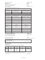
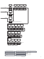
+
-
+
-
+
-
+-
+-
21
2
21
1
1
2
COMMUNICATION FOUNDATION
+
-
7501V107-UK 5
Field mounted HART temperature transmitter
7501
• RTD, TC, Ohm, and bipolar mV input and analog output
• High definition local operator interface (LOI) with 3 optical buttons
• Selectable red or white backlight
• Ex d explosion proof / flameproof in aluminum or 316 stainless steel version
• HART 7 functionality with HART 5 compatibility
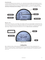
High defintion display
• 0, 90, 180, & 270 degree position adjustments.
• Monitoring, programming and diagnostics view.
• Extensive diagnostics with flashing red or white backlight
• Supports 7 languages.
Local operator interface (LOI)
• 3 optical buttons; up, down and enter.
• Dynamically adaptive to wear or accumulation of dirt.
• Immune to interference from ambient light sources.
• Useable with or without gloves.
Configuration
• From the LOI through the PR guided menu.
• PReset and HART modem.
• HHC, DCS or AMS via HART.
Mounting / installation
• For installation in zone 0, 1, 2 and zone 20, 21, 22,and in
Class 1, Division 1 and 2 applications.
• Hardware assessed for use in SIL 2 applications.
• Mounting on 1.5”–2” pipe bracket or on wall / bulkhead.
Application
• Linearized temperature measurement with TC and RTD
sensors e.g. Pt100 and Ni100.
• HART communication and 4...20 mA analog PV output for
individual, difference or average temperature
measurement of up to two RTD or TC input sensors.
• Conversion of linear resistance to a standard analog
current signal, e.g from valves or Ohmic level sensors.
• Amplification of bipolar mV signals to standard 4...20 mA
current signals.
• Up to 63 transmitters (HART 7) can be connected in a
multidrop communication setup.
Technical characteristics
• NAMUR NE43 and NE89.
• HART protocol revision can be changed by user
configuration to either HART 5 or HART 7 protocol.
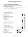
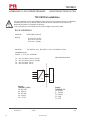
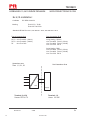
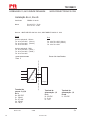
Applications
Input signals:
TC to 4...20 mA
Ex ia: 10...30 VDC
(12...30 VDC with backlight)
Other: 10...35 VDC
(12...35 VDC with backlight)
4...20 mA
Resistance to 4...20 mA
mV to 4...20 mA
Difference or average
RTD, TC or mV
2-wire output and HART:
RTD to 4...20 mA

6 7501V107-UK
Accessories
8550 = 7501 M20 plug text alu encl. silicone O-ring
8550-F = 7501 M20 plug text alu encl. FKM O-ring
8550-S = 7501 M20 plug text stainless steel encl. silicone O-ring
8550-SF = 7501 M20 plug text stainless steel encl. FKM O-ring
8551 = 7501 NPT plug alu encl.
8551-S = 7501 NPT plug text stainless steel encl.
8552 = Pipe-mounting bracket P5-B-N (1½”-2”)
1117 = 5-point calibration certificate
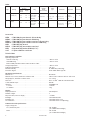
Technical data
Environmental conditions:
Operating tempeature
with silicone O-ring . . . . . . . . . . . . . . . . . . . . . . . . . . . . . . . . . -40°C to +85°C
with FKM O-ring . . . . . . . . . . . . . . . . . . . . . . . . . . . . . . . . . . . -20°C to +85°C
Reduced LCD performance below -20°C and above +70°C
Storage temperature . . . . . . . . . . . . . . . . . . . . . . . . . . . . . . . . . -40°C to +85°C
Calibration temperature. . . . . . . . . . . . . . . . . . . . . . . . . . . . . . . . 20...28°C
Relative humidity . . . . . . . . . . . . . . . . . . . . . . . . . . . . . . . . . . . 0...100% RH (condensing)
Protection degree . . . . . . . . . . . . . . . . . . . . . . . . . . . . . . . . . . . IP54 / IP66 / IP68 / type 4X
Mechanical specifications:
Dimensions . . . . . . . . . . . . . . . . . . . . . . . . . . . . . . . . . . . . . . . Ø 110 mm
Dimensions, H x W x D, aluminum / stainless steel. . . . . . . . . . . . . . . . 109.3 x 145 x 126 mm / 107.4 x 145 x 124
Weight approx., aluminum / stainless steel . . . . . . . . . . . . . . . . . . . . 1.3 / 2.8 kg
Wire size . . . . . . . . . . . . . . . . . . . . . . . . . . . . . . . . . . . . . . . . . 0.13...1.5 mm
2
/ AWG 26...16 stranded wire
Screw terminal torque. . . . . . . . . . . . . . . . . . . . . . . . . . . . . . . . . 0.4 Nm
Vibration. . . . . . . . . . . . . . . . . . . . . . . . . . . . . . . . . . . . . . . . . IEC 60068-2-6
2...25 Hz. . . . . . . . . . . . . . . . . . . . . . . . . . . . . . . . . . . . . . . . ±1.6 mm
25...100 Hz . . . . . . . . . . . . . . . . . . . . . . . . . . . . . . . . . . . . . . ±4 g
Display:
Display resolution . . . . . . . . . . . . . . . . . . . . . . . . . . . . . . . . . . . 96 x 64 pixels
Number of digits . . . . . . . . . . . . . . . . . . . . . . . . . . . . . . . . . . . . 5
Response time, button to display . . . . . . . . . . . . . . . . . . . . . . . . . . < 150 ms
Backlight . . . . . . . . . . . . . . . . . . . . . . . . . . . . . . . . . . . . . . . . Selectable ON / OFF
Backlight color . . . . . . . . . . . . . . . . . . . . . . . . . . . . . . . . . . . . . Selectable white or red
Error indication . . . . . . . . . . . . . . . . . . . . . . . . . . . . . . . . . . . . . Selectable white or red (flashing)
Common electrical specifications:
Supply voltage, DC:
Ex ia, intrinsically safe . . . . . . . . . . . . . . . . . . . . . . . . . . . . . . . 10...30 VDC
(12...30 VDC with backlight)
Other. . . . . . . . . . . . . . . . . . . . . . . . . . . . . . . . . . . . . . . . . . 10...35 VDC
(12...35 VDC with backlight)
Order
Example : 7501A3B1A12
Type Housing
Local operator
interface
O-ring
Conduit
thread
(D1, D2 & D3)
Paint
type
Transmitter Approvals
Cover color
Optical
buttons
Display
7501 Low copper
aluminum (AL)
: A No
No
Yes
No
Yes
Yes
: 1
: 2
: 3
-40 to +85°C
silicone rubber
-20 to +85°C
FKM rubber
: A
: B
M20x1.5 6H
½ NPT mod.
: 1
: 2
Epoxy
Epoxy + poly-
urethane
: A
: B
Yes
No
(comes with
a connection kit)
: 1
: 2
General
purpose
Hazardous
area
: 1
: 2
Red
Grey
: -
: GY
7501 316 Stainless
steel (RF)
: B No
Yes
Yes
Yes
: 2
: 3
-40 to +85°C
silicone rubber
-20 to +85°C
FKM rubber
: A
: B
M20x1.5 6H
½ NPT mod.
: 1
: 2
None : N Yes
No
(comes with
a connection kit)
: 1
: 2
General
purpose
Hazardous
area
: 1
: 2
Steel : -

7501V107-UK 7
Isolation - test / working . . . . . . . . . . . . . . . . . . . . . . . . . . . . . . . 1.5 kVAC / 50 VAC
Signal / noise ratio . . . . . . . . . . . . . . . . . . . . . . . . . . . . . . . . . . . > 60 dB
Programming . . . . . . . . . . . . . . . . . . . . . . . . . . . . . . . . . . . . . . HART
Start-up time (transmitter to display). . . . . . . . . . . . . . . . . . . . . . . . Max. 5 s
Response time (programmable) . . . . . . . . . . . . . . . . . . . . . . . . . . . 1...60 s
Long term stability. . . . . . . . . . . . . . . . . . . . . . . . . . . . . . . . . . . 0.1% of span / year
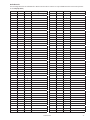
Accuracy, the greater of general and basic values:
TC B
1
accuracy specification range . . . . . . . . . . . . . . . . . . . . . . . . . > 400°C
TC B
2
accuracy specification range . . . . . . . . . . . . . . . . . . . . . . . . . > 160°C < 400°C
TC B
3
accuracy specification range . . . . . . . . . . . . . . . . . . . . . . . . . > 85°C < 160°C
TC B
4
accuracy specification range . . . . . . . . . . . . . . . . . . . . . . . . . < 85°C
TC cold junction compensation. . . . . . . . . . . . . . . . . . . . . . . . . . . . < ±1.0°C
Max. oset on input signal . . . . . . . . . . . . . . . . . . . . . . . . . . . . . . 50% of selec. max. value
Input specifications:
RTD input types:
Pt50, Pt100, Pt200, Pt500, Pt1000, Ni50, Ni100, Ni120, Ni1000
Cable resistance per wire (max.). . . . . . . . . . . . . . . . . . . . . . . . . . . 5 Ω
(up to 50 Ω per wire is possible with reduced measurement accuracy)
Sensor current . . . . . . . . . . . . . . . . . . . . . . . . . . . . . . . . . . . . . Nom. 0.2 mA
RTD
type
Min.
value
Max.
value
Min.
span
Standard
Pt100
Ni100
Lin. R
-200°C
-60°C
0 Ω
+850°C
+250°C
7000 Ω
10°C
10°C
25 Ω
IEC 60751
DIN 43760
-----
EMC - immunity influence. . . . . . . . . . . . . . . . . . . . . . . . . < ±0.1% of span
Extended EMC immunity:
NAMUR NE 21, A criterion, burst . . . . . . . . . . . . . . . . . . . . < ±1% of span
General values
Input type Absolute accuracy Temperature coecient
All ≤ ±0.05% of span ≤ ±0.005% of span / °C
Basic values
Input type Basic accuracy Temperature coecient
Pt50 - Pt1000 ≤ ±0.1°C ≤ ±0.005°C/°C
Ni50 - Ni1000 ≤ ±0.2°C ≤ ±0.005°C/°C
Lin. R ≤ ±0.1 Ω ≤ ±5 mΩ / °C
Volt ≤ ±10 μV ≤ ±0.5 µV / °C
TC type:
E, J, K, L, N, T, U
≤ ±0.5°C
≤ ±0.025°C / °C
TC type:
B
1
, Lr, R, S, W3, W5
≤ ±1°C
≤ ±0.1°C / °C
TC type:B
2
≤ ±3°C ≤ ±0.3°C / °C
TC type:B
3
≤ ±8°C ≤ ±0.8°C / °C
TC type:B
4
not specified not specified

8 7501V107-UK
TC input types:
Cold junction compensation (CJC):
Constant, internal or external via a Pt100 or Ni100 sensor
mV input:
Voltage input range . . . . . . . . . . . . . . . . . . . . . . . . . . . . . . . . . . -800...+800 mV
Min. span . . . . . . . . . . . . . . . . . . . . . . . . . . . . . . . . . . . . . . . . 2.5 mV
Input resistance . . . . . . . . . . . . . . . . . . . . . . . . . . . . . . . . . . . . 10 MΩ
Output specifications:
Signal range. . . . . . . . . . . . . . . . . . . . . . . . . . . . . . . . . . . . . . . 4...20 mA
Min. signal range . . . . . . . . . . . . . . . . . . . . . . . . . . . . . . . . . . . . 16 mA
Updating time . . . . . . . . . . . . . . . . . . . . . . . . . . . . . . . . . . . . . 440 ms
Load resistance. . . . . . . . . . . . . . . . . . . . . . . . . . . . . . . . . . . . . ≤ (Vsupply - 10) / 0.023 [Ω]
with backlight . . . . . . . . . . . . . . . . . . . . . . . . . . . . . . . . . . . . ≤ (Vsupply - 12) / 0.023 [Ω]
Sensor error detection, programmable . . . . . . . . . . . . . . . . . . . . . . . 3.5...23 mA
(shorted sensor error detection is ignored at TC and mV input)
NAMUR NE43 Upscale . . . . . . . . . . . . . . . . . . . . . . . . . . . . . . . . 23 mA
NAMUR NE43 Downscale. . . . . . . . . . . . . . . . . . . . . . . . . . . . . . . 3.5 mA
HART protocol revisions. . . . . . . . . . . . . . . . . . . . . . . . . . . . . . . . HART 7 and HART 5
Marine approval:
EU RO Mutual Recognition Type Approval . . . . . . . . . . . . . . . . . . . . . MRA0000009
Ex approvals:
ATEX 2014/34/EU . . . . . . . . . . . . . . . . . . . . . . . . . . . . . . . . . . . DEKRA 15 ATEX 0058 X
IECEx . . . . . . . . . . . . . . . . . . . . . . . . . . . . . . . . . . . . . . . . . . . IECEx DEK 15.0039 X
cFMus . . . . . . . . . . . . . . . . . . . . . . . . . . . . . . . . . . . . . . . . . . FM16US0009X / FM16CA0010X
cCSAus . . . . . . . . . . . . . . . . . . . . . . . . . . . . . . . . . . . . . . . . . . 70024231
INMETRO . . . . . . . . . . . . . . . . . . . . . . . . . . . . . . . . . . . . . . . . DEKRA 15.0014 X
NEPSI . . . . . . . . . . . . . . . . . . . . . . . . . . . . . . . . . . . . . . . . . . GYJ15.1336X, GYJ15.1337X and
GYJ15.1338X
EAC Ex TR-CU 012/2011 . . . . . . . . . . . . . . . . . . . . . . . . . . . . . . . RU C-DK.GB08.V.01316
Observed authority requirements:
EMC. . . . . . . . . . . . . . . . . . . . . . . . . . . . . . . . . . . . . . . . . . . . 2014/30/EU
RoHS . . . . . . . . . . . . . . . . . . . . . . . . . . . . . . . . . . . . . . . . . . . 2011/65/EU
EAC . . . . . . . . . . . . . . . . . . . . . . . . . . . . . . . . . . . . . . . . . . . . TR-CU 020/2011
Functional Safety:
Hardware assessed for use in SIL 2 applications
FMEDA report - www.prelectronics.com
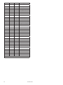
Type
Min.
temperature
Max.
temperature
Min.
span
Standard
B
E
J
K
L
Lr
N
R
S
T
U
W3
W5
0°C
-100°C
-100°C
-180°C
-200°C
-200°C
-180°C
-50°C
-50°C
-200°C
-200°C
0°C
0°C
+1820°C
+1000°C
+1200°C
+1372°C
+900°C
+800°C
+1300°C
+1760°C
+1760°C
+400°C
+600°C
+2300°C
+2300°C
100°C
50°C
50°C
50°C
50°C
50°C
50°C
100°C
100°C
50°C
50°C
100°C
100°C
IEC584
IEC584
IEC584
IEC584
DIN 43710
GOST 3044-84
IEC584
IEC584
IEC584
IEC584
DIN 43710
ASTM E988-90
ASTM E988-90
7501V107-UK 9
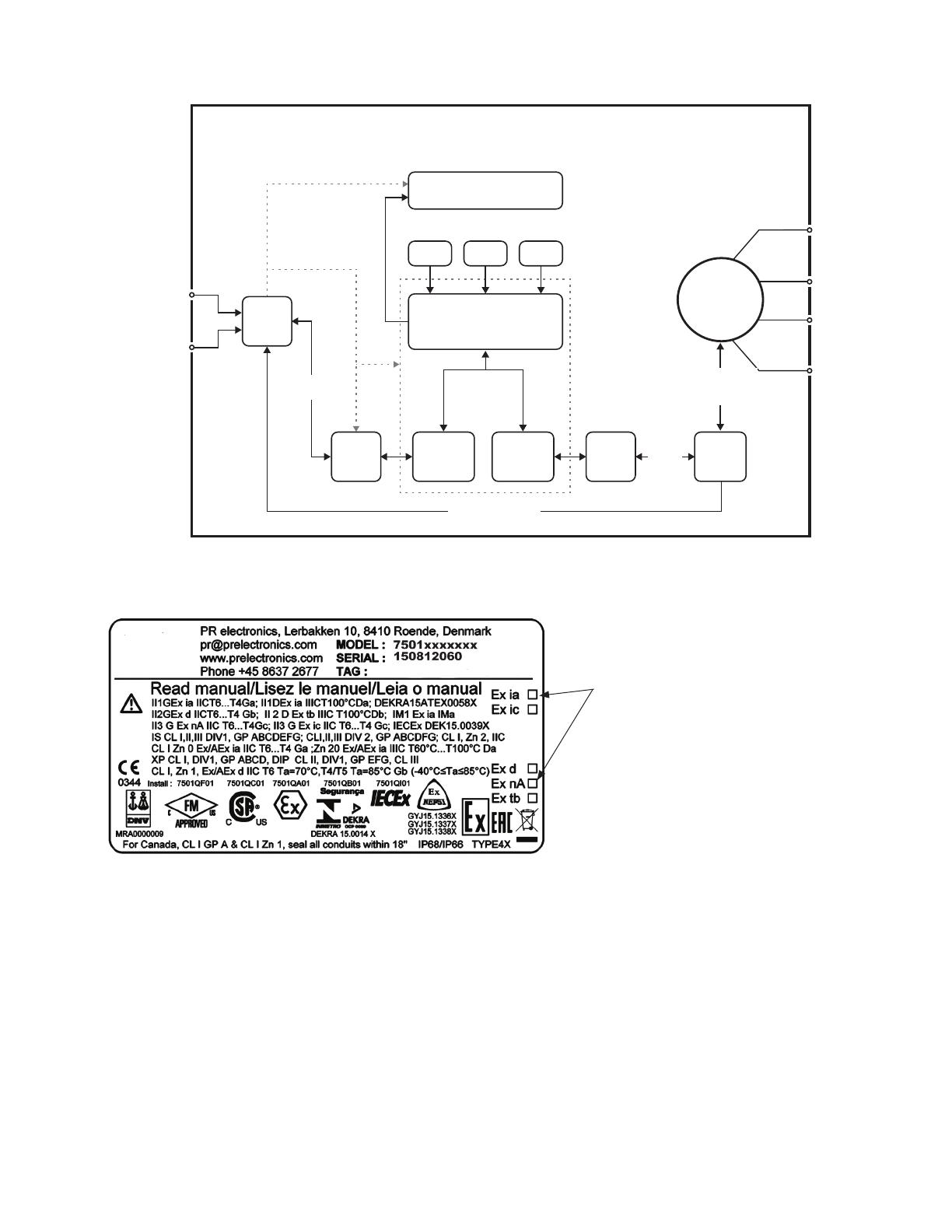
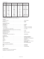
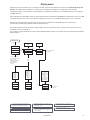
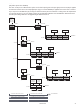
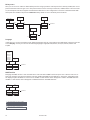
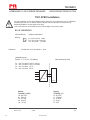
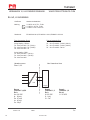
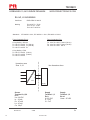
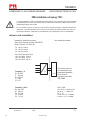
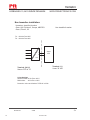
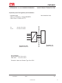
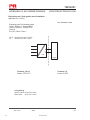
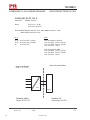
Block diagram
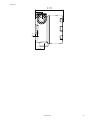
Marking
Caution
The ambient temperature range depends on T rating, type of protection and sealing materials, see the installation drawing.
T1
T2
T3
T4
T5
T6
7501
HART
HART
Application
Sensor
UP DOWN ENTER
HART
slave
HART
“master”
HART
modem
Filter
HART
modem
Supply
Display
5337
HART
transmitter
4...20 mA
+ HART
4...20 mA
+ HART
8 V / 4...20 mA
When this product has been installed as Ex
ia, ic, d, nA or tb, use a punch marker in the
appropriate box to indicate the type of
installation on the top label.

145
127
65
AL: 126
RF: 124
114
64,50
40
D1
D2
D3
145
127
114
64,50
40
D1
D2
D3
AL: 126
RF: 124
10 7501V107-UK
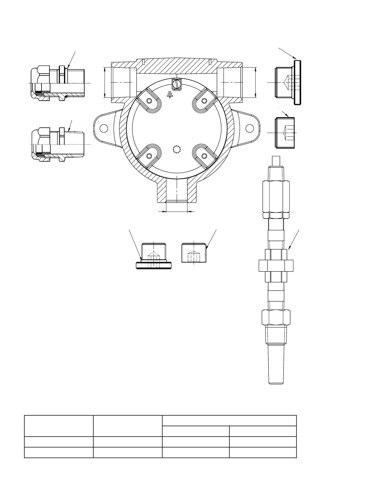
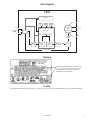
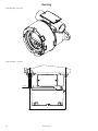
Mechanical specifications
It is important to be careful when screwing the cover on or off. The thread surface must be free of any
grains, pellets or other impurities as these can cause the cover to seize or damage the threads.
! Never use force to screw on the cover.
Should it be necessary to open the connection head cover after operation in maximum temperature,
please be aware that the cover may be blocked (does not give when attempting to open it by hand). In
this case, keep the cover under tension with your hand and hit the cover gently with a rubber hammer.
All dimensions below in mm. AL = aluminum version and RF = stainless steel version.
Front view – with buttons and display
Front view – no buttons or display

AL: 7
RF: 6
AL: 109.3
RF: 107.4
AL: 35
RF: 34
AL: 25 / RF: 24
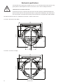
7501V107-UK 11
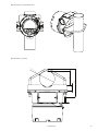
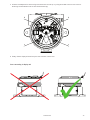
Side view

2 x Ø 7
127
12 7501V107-UK
Mounting
Wall-mounting – side view
Wall-mounting – top view

M6
51
19
98
D = 1½" - 2"
7501V107-UK 13
Pipe-mounting – front and back view
Pipe-mounting – top view
14 7501V107-UK
Protection degree
Blind plug M20 . . . . . . . . . . . . . . . . . . . . . . . . . . . . . . . . . . . . . IP54
With O-ring . . . . . . . . . . . . . . . . . . . . . . . . . . . . . . . . . . . . . . IP66 - IP68
Blind plug ½” NPT MOD . . . . . . . . . . . . . . . . . . . . . . . . . . . . . . . . IP54
With locktite 577 . . . . . . . . . . . . . . . . . . . . . . . . . . . . . . . . . . IP66 - IP68
Protection degree is defined by the connection with the lowest IP rating.
It is optional to connect a sensor to any of the three conduit openings.
Blind plugs are Ex approved only when used together with 7501.
Earth terminal and protection terminal
Placement Type
Cable cross section [mm
2
]
Stranded wire Solid wire
Inside Protection terminal 1.5 2.5
Outside Earth terminal 4.0 6.0
D1
D2
D3
Sealing washer
Threaded sealant
Sealing washer
Threaded sealant
Threaded sealant
SensorSealing washer
Blanking elements
Cable glands
20 x 1.5
½ NPTmod
½ NPTmod
20 x 1.5

A-F = 2mm
1 2
3 3
7501V107-UK 15
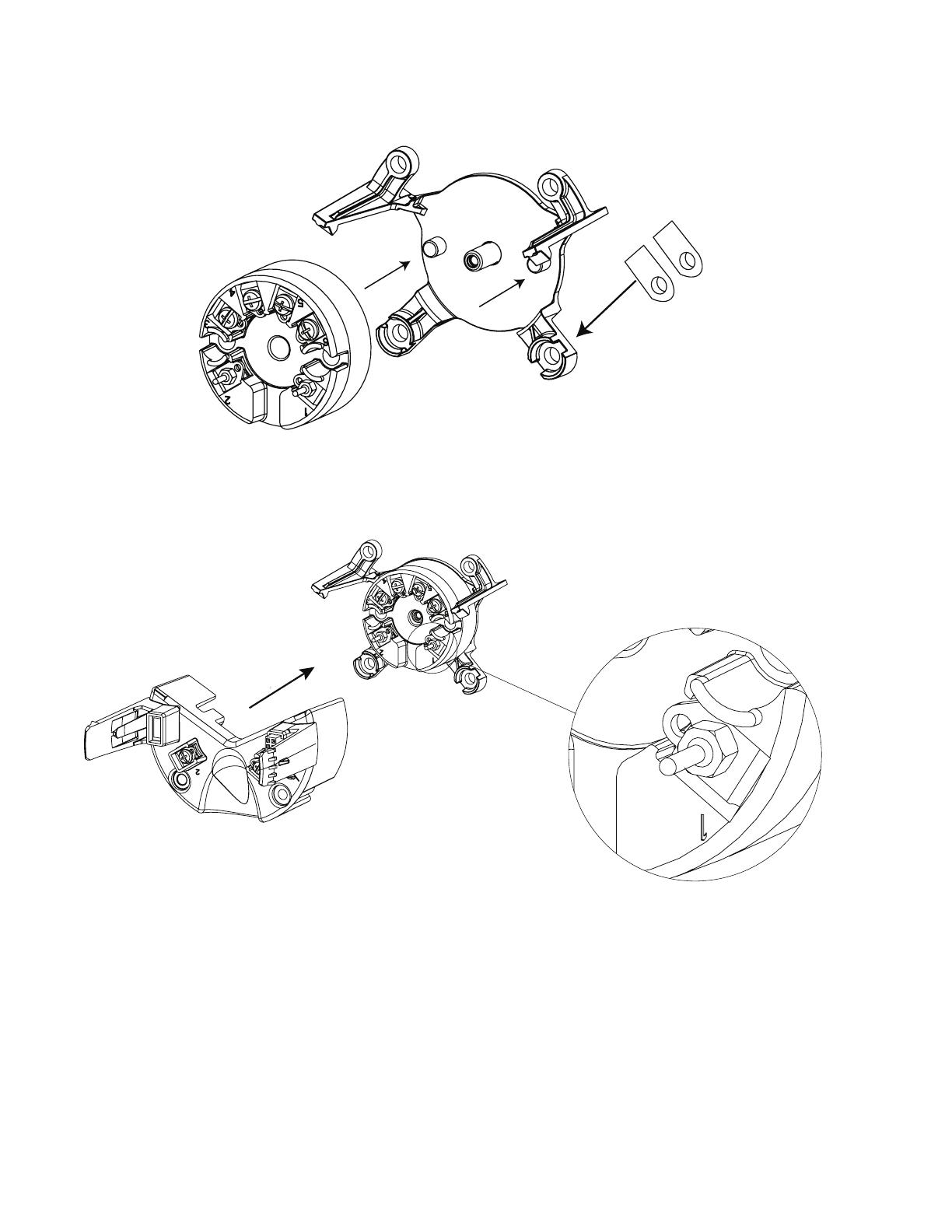
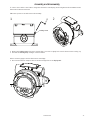
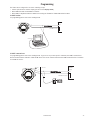
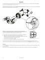
Assembly and disassembly
To connect sensor wires to the 7501 or change the orientation of the display, the housing must be disassembled and the
internal device must be extracted.
!! Disconnect power to the device before disassembly.
1. Release the locking screw, using a hex spanner with a cross-flat of 2 [mm]. This screw is situated on the housing top.
2. Unscrew the housing lid by turning it counterclockwise.
Point 3 and 4 only apply to devices with buttons and display.
3. Press and hold the two clamps located on the left and right side of the display unit.
Locking screw

a a
b b
16 7501V107-UK
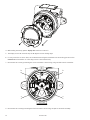
4. While holding the clamps, pull the display unit outwards to remove it.
5. The display can now be turned in steps of 90 degrees for best viewing angle.
6. For easy connection of sensor wires, we recommend extracting the transmitter from the housing (see the section
Connections for information on connecting sensors to the internal 5337).
7. Unscrew the two screws (a) fastening the connector bracket to the housing, using a Posidriv form Z screwdriver.
8. Unscrew the two screws (b) fastening the fixation bracket to the housing, and pull out the entire assembly.

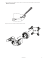
7501V107-UK 17
9. Use a screwdriver (or your fingers) to lever the taps (one on each side) on the fixation bracket to release it from the
transmitter connector bracket.
NB! Do not use excessive force.
10. Separate the connector bracket, transmitter and fixation bracket.
RF
Al
18 7501V107-UK
Assembly
1. Place the transmitter in the fixation bracket using the guidance taps on the bracket. Make sure terminals 1 and 2 are
facing downwards.
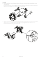
NB. The fixation bracket is not interchangeable between the aluminum and stainless steel housing. Check the bottom
right-hand corner for identifier (Al for aluminum and RF for stainless steel).
2. Slide the connector bracket onto the transmitter using the dovetails as guides. Make sure the golden connector pins on
terminal 1 and 2 on the transmitter slide into place in the corresponding terminals on the connector bracket.
Press the bracket into place until you hear a distinct click.

a a
b b
7501V107-UK 19
3. Slide the assembly back into the housing and refasten the 4 screws (a + b), using the 28 mm screws for the connector
bracket (a) and the 10 mm screws for the fixation bracket (b).
4. Finally, click the display unit back into place and screw the cover back on.
Correct mounting of display unit

20 7501V107-UK
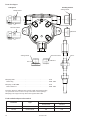
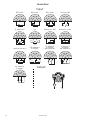
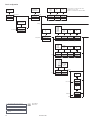
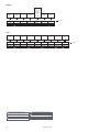
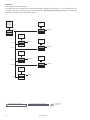
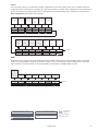
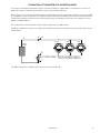
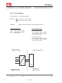
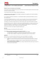
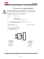
Connections
+
-
12
+
-
1
+
-
2
+
-
+
-
12
+
-
+
-
2 1
3
4
6
5
+
-
3
4
6
5
3
4
6
5
+
-
3
4
6
5
3
4
6
5
3
4
6
5
3
4
6
5
3
4
6
5
3
4
6
5
3
4
6
5
3
4
6
5
3
4
6
5
3
4
6
5
-
+
12
m
A
Output:
Input:
Resistance, 2-wire
Resistance, 3-wire
RTD, 2-wire RTD, 3-wire RTD, 4-wire
TC, internal CJC
TC, external CJC mV
Resistance, 4-wire
TC, dierence
or average,
with external CJC
mV, dierence
or average
RTD, dierence
or average
TC, dierence
or average,
with internal CJC
A página está carregando...
A página está carregando...
A página está carregando...
A página está carregando...
A página está carregando...
A página está carregando...
A página está carregando...
A página está carregando...
A página está carregando...
A página está carregando...
A página está carregando...
A página está carregando...
A página está carregando...
A página está carregando...
A página está carregando...
A página está carregando...
A página está carregando...
A página está carregando...
A página está carregando...
A página está carregando...
A página está carregando...
A página está carregando...
A página está carregando...
A página está carregando...
A página está carregando...
A página está carregando...
A página está carregando...
A página está carregando...
A página está carregando...
A página está carregando...
A página está carregando...
A página está carregando...
A página está carregando...
A página está carregando...
A página está carregando...
A página está carregando...
A página está carregando...
A página está carregando...
A página está carregando...
A página está carregando...
A página está carregando...
A página está carregando...
A página está carregando...
A página está carregando...
A página está carregando...
A página está carregando...
A página está carregando...
A página está carregando...
A página está carregando...
A página está carregando...
-
 1
1
-
 2
2
-
 3
3
-
 4
4
-
 5
5
-
 6
6
-
 7
7
-
 8
8
-
 9
9
-
 10
10
-
 11
11
-
 12
12
-
 13
13
-
 14
14
-
 15
15
-
 16
16
-
 17
17
-
 18
18
-
 19
19
-
 20
20
-
 21
21
-
 22
22
-
 23
23
-
 24
24
-
 25
25
-
 26
26
-
 27
27
-
 28
28
-
 29
29
-
 30
30
-
 31
31
-
 32
32
-
 33
33
-
 34
34
-
 35
35
-
 36
36
-
 37
37
-
 38
38
-
 39
39
-
 40
40
-
 41
41
-
 42
42
-
 43
43
-
 44
44
-
 45
45
-
 46
46
-
 47
47
-
 48
48
-
 49
49
-
 50
50
-
 51
51
-
 52
52
-
 53
53
-
 54
54
-
 55
55
-
 56
56
-
 57
57
-
 58
58
-
 59
59
-
 60
60
-
 61
61
-
 62
62
-
 63
63
-
 64
64
-
 65
65
-
 66
66
-
 67
67
-
 68
68
-
 69
69
-
 70
70


PR electronics 7501 Series Manual do usuário
- Tipo
- Manual do usuário
em outras línguas
Artigos relacionados
Outros documentos
-
Omega TXUN-FD Manual do proprietário
-
-
-
Mitsubishi Heavy Industries eco touch RC-EX1N Guia de instalação
-
-
Videotec MAXIMUS MPXR SERIES2 Manual do usuário
-
Snap-On ControlTech Micro Calibration Procedure
-
Videotec MAXIMUS MMX Manual do usuário
-
Siemens 7ME4603 Installatio And User's Operating Instructions
-
turck AIH401-N Guia rápido