
Radar Transmitters
Quick Start Manual 01/2012
SITRANS LR250 (Foundation Fieldbus)
SITRANS

7ML19985XN82 SITRANS LR250 (FF) – QUICK START MANUAL Page EN-1
mmmmm
English
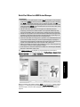
SITRANS LR250 (Foundation Fieldbus)
Quick Start Manual
This manual outlines the essential features and functions of the SITRANS LR250 (Foundation
Fieldbus). We strongly advise you to acquire the detailed version of the manual so you can use
your instrument to its fullest potential. The complete manual can be downloaded from the
product page of our web site at: www.siemens.com/LR250
. The printed manual is available from
your local Siemens representative.
Questions about the contents of this manual can be directed to:
Siemens AG
Siemens Milltronics Process Instruments
1954 Technology Drive, P.O. Box 4225
Peterborough, Ontario, Canada, K9J 7B1
Email: techp[email protected]
MILLTRONICS® is a registered trademark of Siemens Milltronics Process Instruments Inc.
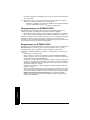
Technical Support
Support is available 24 hours a day.
To find your local Siemens Automation Office address, phone number and fax number go to:
www.siemens.com/automation/partner:
• Click on the tab Contact, select Service, then click Service again to find your product
group (+Automation Technology > +Sensor Systems >+Process Instrumentation > +Level
Measurement > +Continuous). Select Radar.
• Select the country followed by the City/Region.
• Select Technical Support under Service.
For on-line technical support go to: www.siemens.com/automation/support-request
• Enter the instrument name (SITRANS LR250) or order number, then click on Search, and
select the appropriate product type. Click on Next.
• Enter a keyword describing your issue. Click on Next. Then either browse the relevant
documentation, or click on Next to E-mail a description of your issue to Siemens
Technical Support staff.
Siemens IA/DT Technical Support Center: phone +49 (0)911 895 7222
Copyright Siemens AG 2011.
All Rights Reserved
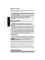
Disclaimer of Liability
We encourage users to purchase autho-
rized bound manuals, or to view elec-
tronic versions as designed and
authored by Siemens Milltronics Process
Instruments Inc. Siemens Milltronics
Process Instruments Inc. will not be
responsible for the contents of partial or
whole reproductions of either bound or
electronic versions.
While we have verified the contents of this manual
for agreement with the instrumentation described,
variations remain possible. Thus we cannot guar-
antee full agreement. The contents of this manual
are regularly reviewed and corrections are
included in subsequent editions. We welcome all
suggestions for improvement.
Technical data subject to change.

Page EN-2 SITRANS LR250 (FF) – QUICK START MANUAL 7ML19985XN82
mmmmm
English
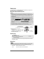
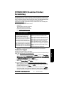
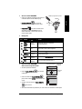
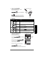
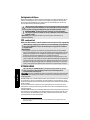
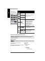
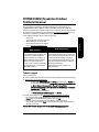
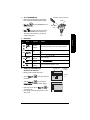
Safety Guidelines
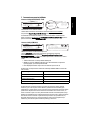
Warning notices must be observed to ensure personal safety as well as that of others, and to
protect the product and the connected equipment. These warning notices are accompanied by
a clarification of the level of caution to be observed.
1)
FCC Conformity
US Installations only: Federal Communications Commission (FCC) rules
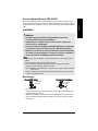
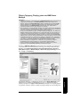
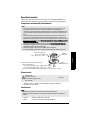
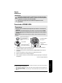
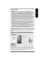
SITRANS LR250
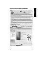
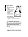
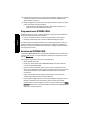
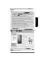
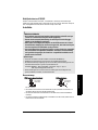
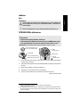
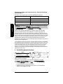
SITRANS LR250 is a 2-wire 25 GHz pulse radar level transmitter for continuous monitoring of
liquids and slurries in storage vessels including high pressure and high temperature, to a range
of 20 m (66 ft). It is ideal for small vessels and low dielectric media.
The instrument consists of an electronic component coupled to a horn antenna and either a
threaded or flange type process connection. A threaded PVDF antenna is also available.
SITRANS LR250 supports Foundation Fieldbus (FF) communication protocol. Signals are
processed using Process Intelligence which has been field-proven in over 1,000,000
applications worldwide (ultrasonic and radar). This instrument can be configured as an FF (H1)
Link Master.
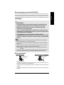
WARNING: relates to a caution symbol on the product, and means that failure to
observe the necessary precautions can result in death, serious injury, and/or
considerable material damage.
WARNING
1
: means that failure to observe the necessary precautions can result
in death, serious injury, and/or considerable material damage.
Note: means important information about the product or that part of the operating manual.
1)
This symbol is used when there is no corresponding caution symbol on the product.
WARNING: Changes or modifications not expressly approved by Siemens
Milltronics could void the user’s authority to operate the equipment.
Notes:
• This equipment has been tested and found to comply with the limits for a Class A digital
device, pursuant to Part 15 of the FCC Rules. These limits are designed to provide
reasonable protection against harmful interference when the equipment is operated in a
commercial environment.
• This equipment generates, uses, and can radiate radio frequency energy and, if not
installed and used in accordance with the instruction manual, may cause harmful
interference to radio communications. Operation of this equipment in a residential area is
likely to cause harmful interference to radio communications, in which case the user will
be required to correct the interference at his own expense.
WARNING: SITRANS LR250 is to be used only in the manner outlined in this manual,
otherwise protection provided by the equipment may be impaired.
Note: This product is intended for use in industrial areas. Operation of this equipment in a
residential area may cause interference to several frequency based communications.

7ML19985XN82 SITRANS LR250 (FF) – QUICK START MANUAL Page EN-3
mmmmm
English
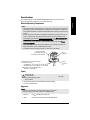
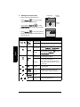
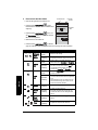
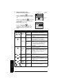
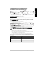
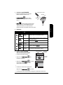
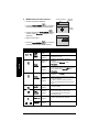
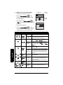
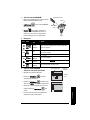
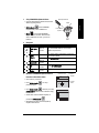
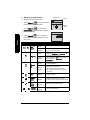
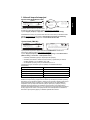
Specifications
For a complete listing, see the SITRANS LR250 (FF) Operating Instructions manual. For
Approvals information, please refer to the process device tag.
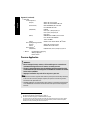
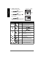
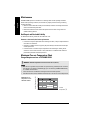
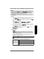
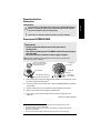
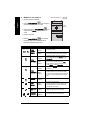
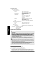
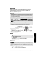
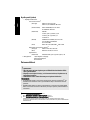
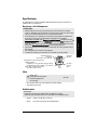
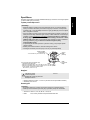
Ambient/Operating Temperature
Power
• Bus powered 9-32 V DC, per IEC 61158-2 (Foundation Fieldbus)
• Current consumed: 20 mA
Approvals
• General CSA
US/C
, CE, FM, NE 21, C-TICK, KC
• Radio FCC, Industry Canada and Europe ETSI EN 302-372
Notes:
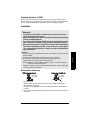
• The maximum temperature is dependent on the process connection, antenna materials,
and vessel pressure: see
Wiring Setups for hazardous area installations
on page 9. For
more detailed information see Process Pressure/Temperature derating curves in the full
manual.
• Process temperature and pressure capabilities are dependent upon information on the
process connection tag. The reference drawing listed on the tag is available on the
product page of our website at www.siemens.com/LR250
, under More Info/Installation
drawings/Level Measurement/Installation Drawings/LR250. Additional information on
process connections is available on the Installation Drawings page under Process
Connection Diagrams.
• Signal amplitude increases with antenna diameter, so use the largest practical size.
• Optional extensions can be installed below the threads.
• See
Maximum Process Temperature Chart
on page 24, for more details.
General Purpose:
Intrinsically Safe:
Non-Sparking/Energy Limited:
Non-incendive:
9-32 V DC
Notes:
• The device nameplate lists the approvals that apply to your device.
• Use appropriate conduit seals to maintain IP or NEMA rating.
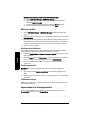
process temperature at process connection:
standard horn antenna:
- with FKM O-ring: –40
o
C to +200
o
C (–40
o
F to +392
o
F)
- with FFKM O-ring: –20
o
C to +200
o
C (–4
o
F to +392
o
F)
2" NPT / BSPT / G Threaded PVDF antenna:
−40 to +80 °C (− 40 to +176 °F)
ambient temperature
(surrounding enclosure)
–40 °C to 80 °C (–40 °F to 176 °F)
device
nameplate
process
connection
tag

Page EN-4 SITRANS LR250 (FF) – QUICK START MANUAL 7ML19985XN82
mmmmm
English
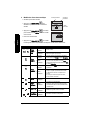
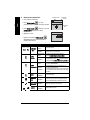
Approvals (continued)
• Hazardous
Intrinsically Safe
1)
(Europe) ATEX II 1G, Ex ia IIC T4 Ga
ATEX II 1D, Ex tD A20 IP67 T90 °C Da
(International) IECEx SIR 09.0148X, Ex ia IIC T4 Ga
Ex tD A20 IP67 T90 °C Da
(US/Canada) FM/CSA
Class I, Div. 1, Groups A, B, C, D
Class II, Div. 1, Groups E, F, G
Class III T4
(Brazil) INMETRO TUV 11.0309 X, Ex ia IIC T4 Ga
Ex ia IIIC T90 ºC Da IP65/IP67
TUV #: OCP 0004
(China) NEPSI Ex ia IIC T4/ DIP A20 T
A,
T90
o
C IP6X
Non-sparking/Energy Limited
2)
(Europe) ATEX II 3G, Ex nA/nL IIC T4 Gc
(China) NEPSI Ex nA II T4/ Ex nL IIC T4
Non-incendive
3)
(US/Canada) FM/CSA Class I, Div. 2, Groups A, B, C, D T5
• Marine Lloyd’s Register of Shipping
ABS Type Approval
Bureau Veritas
Pressure Application
4)
1)
See
Intrinsically Safe wiring1.
on page 11
2)
See
Non-Sparking/Energy Limited wiring2.
on page 12.
3)
See
Non-incendive wiring (only for USA/Canada)3.
on page 13.
WARNINGS:
• Never attempt to loosen, remove, or disassemble process connection or
instrument housing while vessel contents are under pressure.
• The user is responsible for the selection of bolting and gasket materials which
will fall within the limits of the flange and its intended use and which are suitable
for the service conditions.
• Improper installation may result in loss of process pressure.
Notes:
• The process connection tag shall remain with the process pressure boundary assembly
1)
.
In the event the instrument package is replaced, the process connection tag shall be
transferred to the replacement unit.
• SITRANS LR250 units are hydrostatically tested, meeting or exceeding the requirements
of the ASME Boiler and Pressure Vessel Code and the European Pressure Equipment
Directive.
4)
The process pressure boundary assembly comprises the components that act as a barrier against
pressure loss from the process vessel: that is, the combination of process connection body and
emitter, but normally excluding the electrical enclosure.

7ML19985XN82 SITRANS LR250 (FF) – QUICK START MANUAL Page EN-5
mmmmm
English
Pressure Equipment Directive, PED, 97/23/EC
Siemens Level Transmitters with flanged, threaded, or sanitary clamp type process mounts
have no pressure-bearing housing of their own, and therefore do not come under the Pressure
Equipment Directive as pressure or safety accessories (see EU Commission Guideline 1/8 and
1/20).
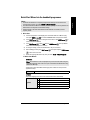
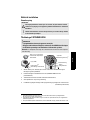
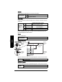
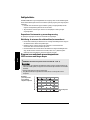
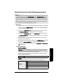
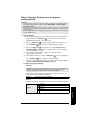
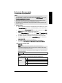
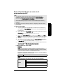
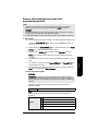
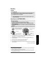
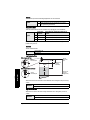
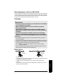
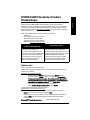
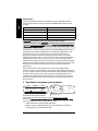
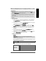
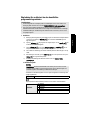
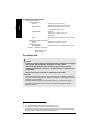
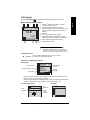
Installation
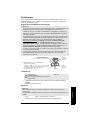
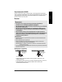
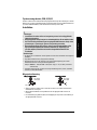
Nozzle design
• The end of the antenna must protrude a minimum of 10 mm (0.4”) to avoid false echoes
being reflected from the nozzle.
• Minimum recommended nozzle diameter for the threaded PVDF antenna is 51 mm (2").
• An antenna extension (100 mm/ 3.93") is available for any version except the threaded
PVDF antenna.
WARNINGS:
• Installation shall be performed only by qualified personnel and in
accordance with local governing regulations.
• Handle the device using the enclosure, not the antenna or the process
connection tag, to avoid damage.
• Take special care when handling the threaded PVDF antenna. Any damage
to the antenna surface, particularly to the tip, could affect performance.
• Materials of construction are chosen based on their chemical compatibility
(or inertness) for general purposes. For exposure to specific environments,
check with chemical compatibility charts before installing.
Notes:
• For European Union and member countries, installation must be according to ETSI EN
302372.
• Refer to the device nameplate for approval information.
• The serial numbers stamped in each process connection body provide a unique
identification number indicating date of manufacture.
Example: MMDDYY – XXX (where MM = month, DD = day, YY = year, and XXX= sequential
unit produced)
• Further markings (space permitting) indicate flange configuration, size, pressure class,
material, and material heat code.
min. clearance:
10 mm (0.4")
Threaded PVDF Antenna Stainless Steel Horn Antenna
Min. dia. 50 mm (2")
min. clearance:
10 mm (0.4")

Page EN-6 SITRANS LR250 (FF) – QUICK START MANUAL 7ML19985XN82
mmmmm
English
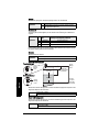
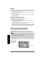
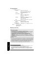
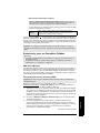
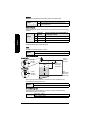
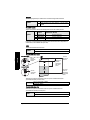
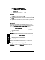
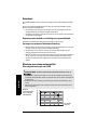
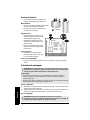
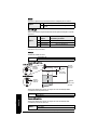
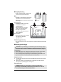
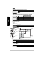
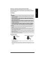
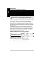
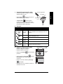
Nozzle location
Avoid central locations on tall, narrow vessels.
Environment
• Provide an environment suitable to the housing
rating and materials of construction.
• Provide a sunshield if the device will be mounted
in direct sunlight.
Beam angle
• Beam angle is the width of the cone
where the energy density is half of the
peak energy density.
• Peak energy density is directly in front
of and in line with the antenna.
• Signal is transmitted outside the beam
angle; therefore false targets may be
detected.
Emission Cone
• Keep emission cone free of interference
from ladders, pipes, I-beams or filling
streams.
Access for programming
• Provide easy access for viewing the display and programming via the handheld
programmer
Mounting instructions
Threaded Versions
1) Before inserting the instrument into its mounting connection, check to ensure the threads
are matching to avoid damaging them.
2) Simply screw the instrument into the process connection, and hand tighten, or use a
wrench. For pressure applications see Warning note above.
Flanged Versions
WARNING: For pressure applications use PTFE tape or other appropriate thread
sealing compound and tighten the process connection beyond hand-tight. The
maximum recommended torque is 40 N-m (30 ft.lbs.)
Note:
• There is no limit to the number of times an instrument can be rotated without damage.
• When mounting, orient the front or back of the instrument towards the closest wall.
• Do not rotate the enclosure after programming and vessel calibration, otherwise an error
may occur, caused by a polarity shift of the transmit pulse.
WARNING: The user is responsible for the selection of bolting and gasket materials
which will fall within the limits of the flange and its intended use, and which are
suitable for the service conditions.
preferred
undesirable
beam angle:
threaded PVDF
antenna = 19°
1.5" horn = 19°
2" horn = 15°
3" horn = 10°
4" horn = 8°
beam
angle
emission
cone

7ML19985XN82 SITRANS LR250 (FF) – QUICK START MANUAL Page EN-7
mmmmm
English
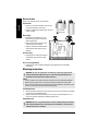
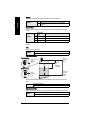
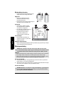
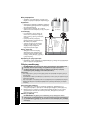
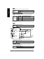
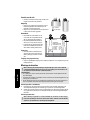
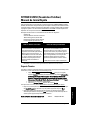
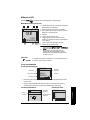
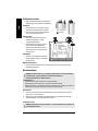
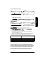
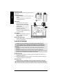
Wiring
Power
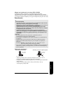
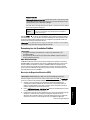
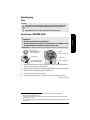
Connecting SITRANS LR250
1)
2)
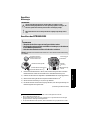
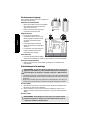
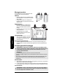
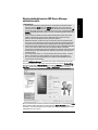
1) Strip the cable jacket for approximately 70 mm (2.75") from the end of the Foundation
Fieldbus cable, and thread the wires through the gland
3)
.
2) Connect the wires to the terminal as shown (SITRANS LR250 FF is not polarity sensitive).
3) Ground the instrument according to local regulations.
4)
4) Tighten the gland to form a good seal.
5) Close the lid and secure the locking ring before programming and instrument
configuration.
(continued on next page)
WARNINGS:
The DC input terminals shall be supplied from a source providing electrical
isolation between the input and output, in order to meet the applicable safety
requirements of IEC 61010-1.
All field wiring must have insulation suitable for rated voltages.
WARNINGS:
• Check the device nameplate to verify the approval rating.
• Use appropriate conduit seals to maintain IP or NEMA rating.
• See
Wiring Setups for hazardous area installations
on page 9.
Note:
For detailed wiring instructions refer to the full LR250 FF Operating Instructions.
1)
The device shield connection is internally connected to the external ground lug.
2)
May be shipped with the instrument.
3)
If cable is routed through conduit, use only approved suitable-size hubs for waterproof applications.
4)
For optimum EMC protection, it is recommended that the FF H1 cable shield be connected to ground at
every node.
cable shield
device shield
connection
1)
external
ground lug
plug (IP 68)
optional cable gland
2)
3)
(or NPT cable entry
3)
)
Use a 2 mm Allen key to
loosen the lid-lock set
screw.

Page EN-8 SITRANS LR250 (FF) – QUICK START MANUAL 7ML19985XN82
mmmmm
English
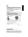
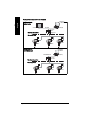
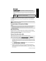
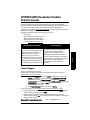
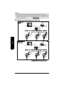
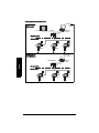
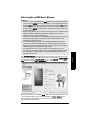
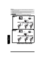
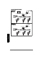
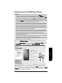
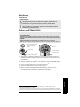
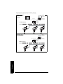
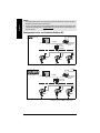
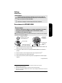
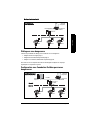
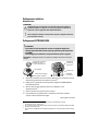
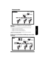
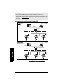
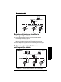
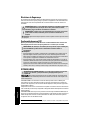
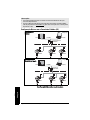
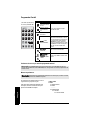
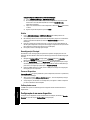
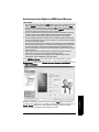
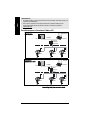
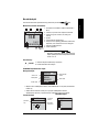
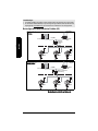
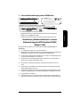
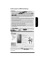
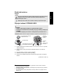
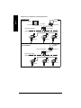
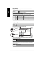
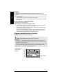
Basic Configuration with Foundation Fieldbus (H1)
Notes:
• Foundation Fieldbus (H1) must be terminated at both extreme ends of the cable for it to
work properly.
• Please refer to the
Foundation Fieldbus System Engineering Guidelines (AG-181) Revision
2.0
, available from www.fieldbus.org, for information on installing FF (H1) devices.
controller
Rosemount
3420 HSE/H1
Gateway
configurator
software
LR250 FF
LR250 FF LR250 FF
PC/laptop
FF (H1)
controller
HSE/H1
Linking Device
LR250 FF
LR250 FF
LR250 FF
PC/laptop
FF (H1)
Configuration via
Gateway
Configuration via
Linking Device
FF (HSE)
FF (HSE)
Basic Configuration cont’d on next page.
configurator
software

7ML19985XN82 SITRANS LR250 (FF) – QUICK START MANUAL Page EN-9
mmmmm
English
Wiring Setups for hazardous area installations
There are three wiring options for hazardous area installations:
•
Intrinsically Safe wiring
on page 11
•
Non-Sparking/Energy Limited wiring
on page 12
•
Non-incendive wiring (only for USA/Canada)
on page 13.
In all cases, check the device nameplate and process connection tag to verify the approval
rating.
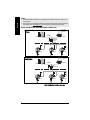
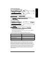
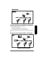
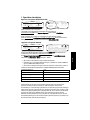
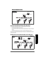
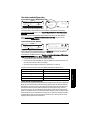
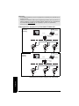
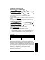
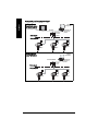
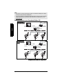
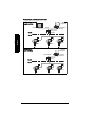
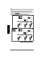
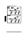
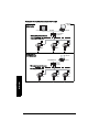
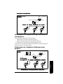
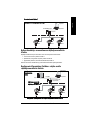
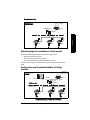
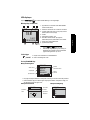
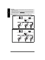
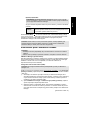
Configuration with Foundation Fieldbus for hazardous
areas
H1 Interface
LR250 FF
LR250 FF LR250 FF
PC/laptop
FF (H1)
Configuration via
PCI/PCMCIA Card
PCI/PCMCIA bus
Basic Configuration cont’d.
configurator
software
Hazardous Area
Non-hazardous Area
controller
EEx ia type
HSE/H1
LR250 FF
LR250 FF
LR250 FF
PC/laptop
FF (H1)
Configuration via
Gateway
FF (HSE)
configurator
software

Page EN-10 SITRANS LR250 (FF) – QUICK START MANUAL 7ML19985XN82
mmmmm
English
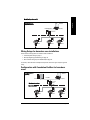
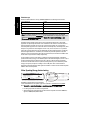
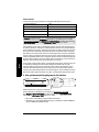
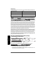
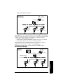
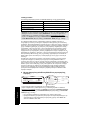
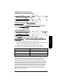
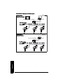
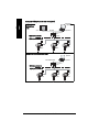
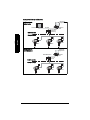
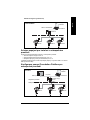
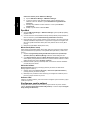
Hazardous Area
Non-hazardous Area
controller
EEx ia type
HSE/H1
Linking Device
LR250 FF
LR250 FF
LR250 FF
PC/laptop
FF (H1)
Configuration via
Linking Device
Hazardous Area
Non-hazardous Area
EEx ia type
H1 Interface
LR250 FF
LR250 FF LR250 FF
PC/laptop
FF (H1)
Configuration via
PCI/PCMCIA Card
FF (HSE)
PCI/PCMCIA bus
Configuration for hazardous areas continued
configurator
software
configurator
software

7ML19985XN82 SITRANS LR250 (FF) – QUICK START MANUAL Page EN-11
mmmmm
English
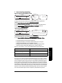
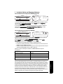
1.Intrinsically Safe wiring
• For wiring requirements: follow local regulations.
• Approved dust-tight and water-tight conduit seals are required for outdoor NEMA 4X /
type 4X / NEMA 6, IP67, IP68 locations.
• Refer to
Instructions specific to hazardous area installations
on page 13.
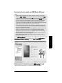
Under the entity evaluation concept, SITRANS LR250 has the following characteristics:
Entity Concept:
The Entity Concept allows interconnection of Intrinsically Safe apparatus to associated
apparatus not specifically examined in such combination. The criteria for interconnection is
that the voltage and current which Intrinsically Safe apparatus can receive and remain
Intrinsically Safe, considering faults, must be equal to or greater than the output voltage (Uo)
and output current (Io) levels which can be delivered by the associated apparatus, considering
faults and applicable factors. In addition, the maximum unprotected capacitance (Ci) and
Inductance (Li) of the Intrinsically Safe apparatus, including interconnecting wiring, must be
equal to or less than the capacitance and inductance which can be safely connected to
associated apparatus.
(input voltage) U
i
= 24 V
(input current) I
i
= 250 mA
(input power) P
i
= 1.2 W
(internal capacitance) Ci = 0
(internal inductance) Li = 0
1 G D EEx ia IIC T4
Ex tD A20 IP67 T90 °C
II
SIRA 09ATEX2353X
Fisco:
Ui = 17.5 V
Ii = 380 mA
Pi = 5.32 W
Ci=0nF
Li=0mH
Entity:
Ui=24V
Ii = 250 mA
Pi = 1.2 W
Ci=0nF
Li=0mH
IECEx SIR 09.0148X
Ex ia IIC T4
Ex tD A20 IP67 T90 °C
0518
SITRANS LR250
Made in Canada
Siemens Milltronics Process Instruments Inc., Peterborough
7MLxxxx-xxxxx-xxxx
Encl.: NEMA / TYPE 4X, 6, IP67, IP68
Amb.Temp.: – 40 °C to 80 °C
Power Rating: 32 V
Max., 20 mA
Serial No: GYZ / A1034567
s
FOUNDATION FIELDBUS
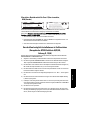
The ATEX certificates listed on the nameplate
can be downloaded from the product page of our website at:
www.siemens.com/LR250
. Go to More Info > Certificates.
Device nameplate (ATEX/IECEx/C-TICK)
The IECEx certificate listed on the nameplate can be viewed on the IECEx website.
Go to: http://iecex.iec.ch
> Ex Equipment Certificates of Conformity and enter the certificate
number IECEx SIR 09.0148X.
Exia per drawing: A5E02358161
R
Fisco:
Ui = 17.5 V
Ii = 380 mA
Pi = 5.32 W
Ci=0nF
Li=0mH
Entity:
Ui=24V
Ii = 250 mA
Pi = 1.2 W
Ci=0nF
Li=0mH
Class I, Div 1, Gr. A, B,C, D
Class II, Div 1, Gr. E, F, G
Class III T4
This device complies with Part 15 of the FCC Rules. Operation is subject to the following two
conditions 1)This device may not cause harmful interference and 2)This device must accept
any interference received, including interference that may cause undesired operation
IC: 267P-LR250
FCC ID: NJA-LR250
SITRANS LR250
Made in Canada
Siemens Milltronics Process Instruments Inc., Peterborough
7MLxxxx-xxxxx-xxxx
Encl.: NEMA / TYPE 4X, 6, IP67, IP68
Amb.Temp.: – 40 °C to 80 °C
Power Rating: 32 V
Max., 20 mA
Serial No: GYZ / A1034567
s
FOUNDATION FIELDBUS
The FM/CSA Intrinsically Safe connection drawing
number A5E02358161 can be downloaded from the product page of our website at:
www.siemens.com/LR250
.
Go to More Info > Installation Drawings > Level Measurement > SITRANS LR250.
Device nameplate (FM/CSA)

Page EN-12 SITRANS LR250 (FF) – QUICK START MANUAL 7ML19985XN82
mmmmm
English
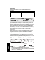
FISCO Concept
Under the FISCO evaluation concept, SITRANS LR250 has the following characteristics:
The FISCO Concept allows interconnection of Intrinsically Safe apparatus to associated
apparatus not specifically examined in such combination. The criteria for interconnection is
that the voltage (Ui or Vmax), the current (Ii, or Imax) and the power (Pi, or Pmax) which
Intrinsically Safe apparatus can receive and remain Intrinsically Safe, considering faults, must
be equal to or greater than the voltage (Uo or Voc or Vi), the current (lo or Isc or li), and the
power (Po or Pmax) levels which can be delivered by the associated apparatus, considering
faults and applicable factors. In addition, the maximum unprotected capacitance (Ci) and
inductance (Li) of each apparatus (other than the termination) connected to the fieldbus must
be less than or equal to 5 nF and 10 μH respectively.
In each segment only one active device, normally the associated apparatus, is allowed to
provide the necessary energy for the fieldbus system. The allowed voltage Uo (or Voc or Vt) of
the associated apparatus is limited to the range of 14V dc to 24V dc. All other equipment
connected to the bus cable has to be passive, meaning that they are not allowed to provide
energy to the system, except for a leakage current of 50 μA for each connected device.
Separately powered equipment needs a galvanic isolation to assure that the Intrinsically Safe
fieldbus circuit remains passive.
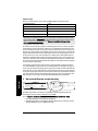
2.Non-Sparking/Energy Limited wiring
• For wiring requirements: follow local regulations.
• Approved dust-tight and water-tight conduit seals are required for outdoor NEMA 4X /
type 4X / NEMA 6, IP67, IP68 locations.
(input voltage) U
i
= 17.5 V
(input current) I
i
= 380 mA
(input power) P
i
= 5.32 W
(internal capacitance) Ci = 0
(internal inductance) Li = 0
Note: For complete details and instructions regarding the FISCO Concept The FM/CSA
connection drawing number A5E02358161 can be downloaded from the product page of our
website at: www.siemens.com/LR250
. Go to More Info > Installation Drawings > Level
Measurement > SITRANS LR250.
SITRANS LR250
Made in Canada
Siemens Milltronics Process Instruments Inc., Peterborough
7MLxxxx-xxxxx-xxxx
Encl.: NEMA / TYPE 4X, 6, IP67, IP68
Amb.Temp.: – 40 °C to 80 °C
Power Rating: 32 V
Max., 20 mA
Serial No: GYZ / A1034567
Warning:
Potential Electrostatic Charging Hazard Do Not Clean
Probe With A Dry Cloth.
Do Not Install Where Build-Up Of Charge Is Likely.
Use Cable Rated > 90°C
3GII
SIRA 09ATEX4354X
EEx nL IIC T4 Gc
FNICO:
Ui = 17.5 V
Ii = 570 mA
Pi = 7.98 W
Ci<5nF
Li<20µH
Entity:
Ui=32V
Ci<5nF
Li<20µH
EEx nA II T4 Gc
Un=32V
s
FOUNDATION FIELDBUS
The ATEX certificate listed on the nameplate
can be downloaded from the product page of our website at: www.siemens.com/LR250
.
Go to More Info > Installation Drawings > Level Measurement > SITRANS LR250.

7ML19985XN82 SITRANS LR250 (FF) – QUICK START MANUAL Page EN-13
mmmmm
English
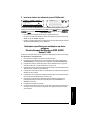
3.Non-incendive wiring (only for USA/Canada)
• For wiring requirements: follow local regulations.
• Approved dust-tight and water-tight conduit seals are required for outdoor NEMA 4X /
type 4X / NEMA 6, IP67, IP68 locations.
• Refer to
Instructions specific to hazardous area installations
below.
Instructions specific to hazardous area installations
(Reference European ATEX Directive 94/9/EC,
Annex II, 1/0/6)
The following instructions apply to equipment covered by certificate number SIRA
09ATEX2353X and 09ATEX4354X:
1) For use and assembly, refer to the main instructions.
2) The equipment is certified for use as Category 1GD equipment per SIRA 09ATEX2353X
certificate and as Category 3G per SIRA 09ATEX4354X certificate.
3) The equipment may be used with flammable gases and vapors with apparatus group IIC,
IIB and IIA and temperature classes T1, T2, T3 andT4.
4) The equipment has a degree of ingress protection of IP67 and a temperature class of
T90
o
C and may be used with flammable dusts.
5) The equipment is certified for use in an ambient temperature range of –40
o
C to +80
o
C.
6) The equipment has not been assessed as a safety related device (as referred to by
Directive 94/9/EC Annex II, clause 1.5).
7) Installation and inspection of this equipment shall be carried out by suitably trained
personnel in accordance with the applicable code of practice (EN 60079-14 and EN 60079-
17 in Europe).
8) The equipment is non-repairable.
9) The certificate numbers have an ’X’ suffix, which indicates that special conditions for safe
use apply. Those installing or inspecting this equipment must have access to the
certificates.
Class I, Div. 2,
Gr.A,B,C,D;
Temp. Code: T5
This device complies with Part 15 of the FCC Rules.
Operation is subject to the following two conditions
1)This device may not cause harmful interference and
2)This device must accept any interference received,
including interference that may cause undesired operation
IC: 267P-LR250
FCC ID: NJA-LR250
159134
SITRANS LR250
Made in Canada
Siemens Milltronics Process Instruments Inc., Peterborough
7MLxxxx-xxxxx-xxxx
Encl.: NEMA / TYPE 4X, 6, IP67, IP68
Amb.Temp.:–40°Cto80°C
Power Rating: 32 V
Max., 20 mA
Serial No: GYZ / A1034567
s
FOUNDATION FIELDBUS
FM/CSA Class 1, Div 2 connection drawing number 23650673
can be downloaded from the product page of our website at: www.siemens.com/LR250
.
Go to More Info > Installation Drawings > Level Measurement > SITRANS LR250.

Page EN-14 SITRANS LR250 (FF) – QUICK START MANUAL 7ML19985XN82
mmmmm
English
10) If the equipment is likely to come into contact with aggressive substances, then it is the
responsibility of the user to take suitable precautions that prevent it from being adversely
affected, thus ensuring that the type of protection is not compromised.
11) Aggressive substances:e.g. acidic liquids or gases that may attack metals, or solvents
that may affect polymeric materials.
• Suitable precautions:e.g. establishing from the material’s data sheet that it is
resistant to specific chemicals.
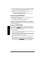
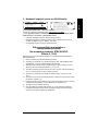
Programming SITRANS LR250
A Quick Start Wizard provides an easy step-by-step guide to help you configure the instrument
for a simple application.
• See
Quick Start Wizard via the handheld programmer
on page 19.
• See
Quick Start Wizard via AMS Device Manager
on page 23.
Settings can be modified locally via the Local User Interface (see
Accessing parameters via
the handheld programmer
on page 16) or remotely via AMS Device Manager. The Local User
Interface (LUI) consists of an LCD display and a handheld programmer.
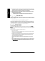
Activating SITRANS LR250
Out of the box, SITRANS LR250 will not begin measurements, and all blocks will be Out of
Service until the instrument has been configured via the local user interface (LUI), or a remote
configuration tool.
Follow these steps to configure the instrument via the LUI:
• Power up the instrument
• The LCD at startup will show LANGUAGE. Edit or cancel this selection. When complete,
the instrument will show QUICK START.
• Complete the Quick Start Wizard (see
Quick Start Wizard via the handheld programmer
on page 19). Completing the Quick Start Wizard or writing any parameter via the LUI
causes the instrument to begin measuring.
• The Resource Block (RES) and Level Transducer Block (LTB) will move to Automatic
mode.
• AIFB 1 and AIFB 2 will remain Out of Service (as displayed on the LCD). These blocks can
only be configured and scheduled using a network configuration tool. For more details,
see System Integration in manual
Foundation Fieldbus for Level Instruments
(7ML19985MP01).

7ML19985XN82 SITRANS LR250 (FF) – QUICK START MANUAL Page EN-15
mmmmm
English
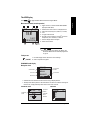
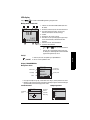
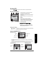
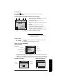
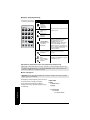
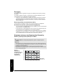
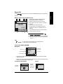
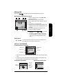
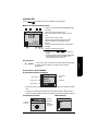
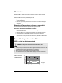
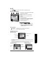
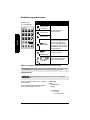
The LCD Display
Press Mode to toggle between Measurement and Program Mode.
Measurement mode (normal operation)
Fault present
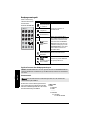
PROGRAM mode display
• A visible menu bar indicates the menu list is too long to display all items.
• The depth and relative position of the item band on the menu bar indicates the length of
the menu list, and approximate position of the current item in the list.
M
[]
FB 1
21.40 °C
NO DATA EXCH.
18.91
1 – toggle indicator
1)
to switch between AIFB 1/AIFB 2
(displayed as FB 1/FB 2)
2 – identifies which block is source of displayed value
3 – measured value (level, space, distance, or volume)
4 – units
5 – bar graph indicates level
6 – secondary region indicates on request
2)
electronics
temperature, echo confidence, or distance
7 – text area displays status messages
8 – device status indicator
1)
Press UP or DOWN arrow to switch.
2)
In response to a key press request. For details, see
Quick Start Wizard via the handheld programmer
on page 19
.
678
1342
5
S: 0 LOE
7 – text area displays a fault code and an error message
8 – service required icon appears
current item
number
current item
current menu
menu bar
Navigation view
item band
SIGNAL PRO..
TVT SETUP
SAMPLING
ECHO QUALITY
2.5.10
ECHO SELECT
parameter
value/
selection
parameter
number
parameter
name
Edit view
Parameter view
%
LEVEL UNIT
PREVIOUS
NEXT
EDITBACK
2.3.2
LEVEL UNIT
MM
FT
2.3.2
IN
%

Page EN-16 SITRANS LR250 (FF) – QUICK START MANUAL 7ML19985XN82
mmmmm
English
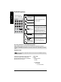
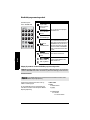
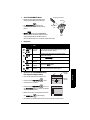
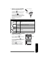
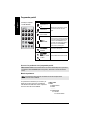
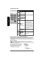
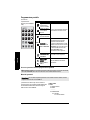
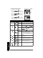
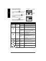
Handheld Programmer
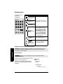
Accessing parameters via the handheld programmer
Parameter menus
Parameters are identified by name and organized
into function groups. For the complete list of
parameters with instructions, see the full LR250 FF
Operating Instructions manual.
Note: SITRANS LR250 automatically returns to Measurement mode after a period of
inactivity in PROGRAM mode (between 15 seconds and 10 minutes, depending on the menu
level).
Note: For the complete list of parameters with instructions, see the full LR250 FF Operating
Instructions manual.
Key Function Result
Updates internal
enclosure temper-
ature reading.
New value is displayed in LCD
secondary region.
Updates echo
confidence value.
Updates distance
measurement.
Mode opens
PROGRAM mode–
Opens the menu level last dis-
played in this power cycle, unless
power has been cycled since exit-
ing PROGRAM mode or more than
10 minutes have elapsed since
PROGRAM mode was used. Then
top level menu will be displayed.
Right ARROW
opens PROGRAM
mode–
Opens the top level menu.
Up or Down
ARROW
toggles between
AIFB 1 and AIFB 2.
Identifies which AIFB is the
source of the displayed value.
C
(Ordered separately:
Part No. 7ML1930-1BK)
1. QUICK START
2. SETUP
2.1. IDENTIFICATION
2.2. DEVICE
..................
2.4. LINEARIZATION
2.4.1. VOLUME
2.4.1.1.VESSEL SHAPE

7ML19985XN82 SITRANS LR250 (FF) – QUICK START MANUAL Page EN-17
mmmmm
English
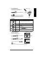
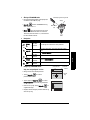
1. Enter PROGRAM mode
• Point the programmer at the display (from a
maximum distance of 300 mm [1 ft]).
• Right ARROW activates PROGRAM mode
and opens menu level 1.
• Mode opens the menu level last displayed
in PROGRAM mode within the last 10 minutes, or
menu level 1 if power has been cycled since then.
2. Navigating
3. Editing in PROGRAM mode
Selecting a listed option:
• Navigate to the desired parameter.
• Press Right ARROW to open parameter
view.
• Press Right ARROW again to open Edit
mode. The current selection is highlighted.
•
• Scroll to a new selection. Press Right ARROW
to accept it
• The LCD returns to parameter view and displays the new selection.
Key Name Menu level Function
Up/Down
ARROW
menu or
parameter
Scroll to previous or next menu or parameter.
Right
ARROW
menu Go to first parameter in selected menu/open next menu.
parameter Open Edit mode.
Left
ARROW
menu or
parameter
Open parent menu.
Mode
menu or
parameter
Change to MEASUREMENT mode.
Home
menu or
parameter
Open top level menu: menu 1.
display
handheld programmer
Max. 300 mm
(1 ft)
parameter name
parameter
number
current
selection
%
LEVEL UNIT
PREVIOUS
NEXT
EDITBACK
2.3.2
LEVEL UNIT
MM
FT
2.3.2
IN
%

Page EN-18 SITRANS LR250 (FF) – QUICK START MANUAL 7ML19985XN82
mmmmm
English
4. Changing a numeric value:
• Navigate to the desired parameter.
• Press Right ARROW to open parameter
view. The current value is displayed.
• Press Right ARROW again to open Edit
mode. The current value is highlighted.
• Key in a new value.
• Press Right ARROW to accept it. The LCD
returns to parameter view and displays the new
selection.
Key Name Function
Up or
Down
ARROW
Selecting
options
• Scrolls to item.
Numeric
editing
• Increments or decrements digits
• Toggles plus and minus sign
Right
ARROW
Selecting
options
• Accepts data (writes the parameter)
• Changes from Edit to Navigation mode
Numeric
editing
• Moves cursor one space to the right
• or with cursor on Enter sign, accepts data and
switches from Edit to Navigation mode
Left
ARROW:
Selecting
options
•Cancels Edit mode without changing the param-
eter
Numeric
editing
• Moves cursor to plus/minus sign if this is the
first key pressed
• or moves cursor one space to the left
• or with cursor on Enter sign, cancels the entry.
Clear
Numeric
editing
• Erases the display.
Decimal
point
Numeric
editing
• Enters a decimal point
• Captures the current path and displays corre-
sponding value in LCD secondary region
Plus or
minus sign
Numeric
editing
• Changes the sign of the entered value.
to
Numeral
Numeric
editing
• Enters the corresponding character.
0.200 M
+0.200
NEAR RANGE
2.5.1
0.200 M
NEAR RANGE
PREVIOUS
NEXT
EDITBACK
2.5.1
current
value
parameter
number
parameter name

7ML19985XN82 SITRANS LR250 (FF) – QUICK START MANUAL Page EN-19
mmmmm
English
Quick Start Wizard via the handheld programmer
1. Quick Start
a) Point the programmer at the display [from a maximum distance of 300 mm (1 ft)],
then press RIGHT arrow to activate PROGRAM mode and open menu level 1.
b) Press RIGHT arrow twice to navigate to menu item 1.1 and DOWN arrow to
enter the Quick Start Wizard.
c) Press RIGHT arrow to open Edit mode or DOWN arrow to accept default
values and move directly to the next item.
d) To change a setting, scroll to the desired item or key in a new value.
e) After modifying a value, press RIGHT arrow to accept it and press DOWN arrow
to move to the next item.
f) Quick Start settings take effect only after you select Finish in Wizard Complete.
1.1. Quick Start Wizard
Introduction
Introduction to Quick Start Wizard showing purpose of wizard: to setup common
applications easily.
Language
Selects the language to be used on the LCD and takes effect immediately.
Notes:
• The Quick Start Wizard is a complete package and the settings are inter-related and
changes apply only after you select FINISH in Wizard Complete.
• Each time the Quick Start Wizard is initiated, the start-up settings are factory defaults. The
Wizard will not recall previous user-defined settings
• Default settings in the Quick Start Wizard are indicated with an asterisk (*) unless
explicitly stated.
Note: The introduction screen is displayed only on the instrument when using the
handheld programmer. This screen is not part of the Quick Start Wizard when using
AMS Device Manager.
Options
CANCEL, NEXT
Options
* ENGLISH
DEUTSCH
FRANÇAIS
ESPAÑOL
简体中文
A página está carregando...
A página está carregando...
A página está carregando...
A página está carregando...
A página está carregando...
A página está carregando...
A página está carregando...
A página está carregando...
A página está carregando...
A página está carregando...
A página está carregando...
A página está carregando...
A página está carregando...
A página está carregando...
A página está carregando...
A página está carregando...
A página está carregando...
A página está carregando...
A página está carregando...
A página está carregando...
A página está carregando...
A página está carregando...
A página está carregando...
A página está carregando...
A página está carregando...
A página está carregando...
A página está carregando...
A página está carregando...
A página está carregando...
A página está carregando...
A página está carregando...
A página está carregando...
A página está carregando...
A página está carregando...
A página está carregando...
A página está carregando...
A página está carregando...
A página está carregando...
A página está carregando...
A página está carregando...
A página está carregando...
A página está carregando...
A página está carregando...
A página está carregando...
A página está carregando...
A página está carregando...
A página está carregando...
A página está carregando...
A página está carregando...
A página está carregando...
A página está carregando...
A página está carregando...
A página está carregando...
A página está carregando...
A página está carregando...
A página está carregando...
A página está carregando...
A página está carregando...
A página está carregando...
A página está carregando...
A página está carregando...
A página está carregando...
A página está carregando...
A página está carregando...
A página está carregando...
A página está carregando...
A página está carregando...
A página está carregando...
A página está carregando...
A página está carregando...
A página está carregando...
A página está carregando...
A página está carregando...
A página está carregando...
A página está carregando...
A página está carregando...
A página está carregando...
A página está carregando...
A página está carregando...
A página está carregando...
A página está carregando...
A página está carregando...
A página está carregando...
A página está carregando...
A página está carregando...
A página está carregando...
A página está carregando...
A página está carregando...
A página está carregando...
A página está carregando...
A página está carregando...
A página está carregando...
A página está carregando...
A página está carregando...
A página está carregando...
A página está carregando...
A página está carregando...
A página está carregando...
A página está carregando...
A página está carregando...
A página está carregando...
A página está carregando...
A página está carregando...
A página está carregando...
A página está carregando...
A página está carregando...
A página está carregando...
A página está carregando...
A página está carregando...
A página está carregando...
A página está carregando...
A página está carregando...
A página está carregando...
A página está carregando...
A página está carregando...
A página está carregando...
A página está carregando...
A página está carregando...
A página está carregando...
A página está carregando...
A página está carregando...
A página está carregando...
A página está carregando...
A página está carregando...
A página está carregando...
A página está carregando...
A página está carregando...
A página está carregando...
A página está carregando...
A página está carregando...
A página está carregando...
A página está carregando...
A página está carregando...
A página está carregando...
A página está carregando...
A página está carregando...
A página está carregando...
A página está carregando...
A página está carregando...
A página está carregando...
A página está carregando...
A página está carregando...
A página está carregando...
A página está carregando...
A página está carregando...
A página está carregando...
A página está carregando...
A página está carregando...
A página está carregando...
A página está carregando...
A página está carregando...
A página está carregando...
A página está carregando...
A página está carregando...
A página está carregando...
A página está carregando...
A página está carregando...
A página está carregando...
A página está carregando...
A página está carregando...
A página está carregando...
A página está carregando...
A página está carregando...
A página está carregando...
A página está carregando...
A página está carregando...
A página está carregando...
A página está carregando...
A página está carregando...
A página está carregando...
A página está carregando...
A página está carregando...
A página está carregando...
A página está carregando...
A página está carregando...
A página está carregando...
A página está carregando...
A página está carregando...
A página está carregando...
A página está carregando...
A página está carregando...
A página está carregando...
A página está carregando...
A página está carregando...
A página está carregando...
A página está carregando...
A página está carregando...
A página está carregando...
A página está carregando...
A página está carregando...
A página está carregando...
A página está carregando...
A página está carregando...
A página está carregando...
A página está carregando...
A página está carregando...
A página está carregando...
A página está carregando...
A página está carregando...
A página está carregando...
A página está carregando...
A página está carregando...
A página está carregando...
A página está carregando...
A página está carregando...
A página está carregando...
A página está carregando...
A página está carregando...
A página está carregando...
A página está carregando...
A página está carregando...
A página está carregando...
A página está carregando...
A página está carregando...
A página está carregando...
A página está carregando...
A página está carregando...
A página está carregando...
A página está carregando...
A página está carregando...
A página está carregando...
A página está carregando...
A página está carregando...
A página está carregando...
A página está carregando...
A página está carregando...
A página está carregando...
A página está carregando...
A página está carregando...
A página está carregando...
A página está carregando...
A página está carregando...
A página está carregando...
A página está carregando...
A página está carregando...
A página está carregando...
A página está carregando...
A página está carregando...
A página está carregando...
A página está carregando...
A página está carregando...
A página está carregando...
A página está carregando...
A página está carregando...
A página está carregando...
A página está carregando...
A página está carregando...
A página está carregando...
A página está carregando...
A página está carregando...
A página está carregando...
A página está carregando...
A página está carregando...
A página está carregando...
A página está carregando...
A página está carregando...
A página está carregando...
A página está carregando...
A página está carregando...
A página está carregando...
A página está carregando...
A página está carregando...
A página está carregando...
A página está carregando...
A página está carregando...
A página está carregando...
A página está carregando...
A página está carregando...
A página está carregando...
A página está carregando...
-
 1
1
-
 2
2
-
 3
3
-
 4
4
-
 5
5
-
 6
6
-
 7
7
-
 8
8
-
 9
9
-
 10
10
-
 11
11
-
 12
12
-
 13
13
-
 14
14
-
 15
15
-
 16
16
-
 17
17
-
 18
18
-
 19
19
-
 20
20
-
 21
21
-
 22
22
-
 23
23
-
 24
24
-
 25
25
-
 26
26
-
 27
27
-
 28
28
-
 29
29
-
 30
30
-
 31
31
-
 32
32
-
 33
33
-
 34
34
-
 35
35
-
 36
36
-
 37
37
-
 38
38
-
 39
39
-
 40
40
-
 41
41
-
 42
42
-
 43
43
-
 44
44
-
 45
45
-
 46
46
-
 47
47
-
 48
48
-
 49
49
-
 50
50
-
 51
51
-
 52
52
-
 53
53
-
 54
54
-
 55
55
-
 56
56
-
 57
57
-
 58
58
-
 59
59
-
 60
60
-
 61
61
-
 62
62
-
 63
63
-
 64
64
-
 65
65
-
 66
66
-
 67
67
-
 68
68
-
 69
69
-
 70
70
-
 71
71
-
 72
72
-
 73
73
-
 74
74
-
 75
75
-
 76
76
-
 77
77
-
 78
78
-
 79
79
-
 80
80
-
 81
81
-
 82
82
-
 83
83
-
 84
84
-
 85
85
-
 86
86
-
 87
87
-
 88
88
-
 89
89
-
 90
90
-
 91
91
-
 92
92
-
 93
93
-
 94
94
-
 95
95
-
 96
96
-
 97
97
-
 98
98
-
 99
99
-
 100
100
-
 101
101
-
 102
102
-
 103
103
-
 104
104
-
 105
105
-
 106
106
-
 107
107
-
 108
108
-
 109
109
-
 110
110
-
 111
111
-
 112
112
-
 113
113
-
 114
114
-
 115
115
-
 116
116
-
 117
117
-
 118
118
-
 119
119
-
 120
120
-
 121
121
-
 122
122
-
 123
123
-
 124
124
-
 125
125
-
 126
126
-
 127
127
-
 128
128
-
 129
129
-
 130
130
-
 131
131
-
 132
132
-
 133
133
-
 134
134
-
 135
135
-
 136
136
-
 137
137
-
 138
138
-
 139
139
-
 140
140
-
 141
141
-
 142
142
-
 143
143
-
 144
144
-
 145
145
-
 146
146
-
 147
147
-
 148
148
-
 149
149
-
 150
150
-
 151
151
-
 152
152
-
 153
153
-
 154
154
-
 155
155
-
 156
156
-
 157
157
-
 158
158
-
 159
159
-
 160
160
-
 161
161
-
 162
162
-
 163
163
-
 164
164
-
 165
165
-
 166
166
-
 167
167
-
 168
168
-
 169
169
-
 170
170
-
 171
171
-
 172
172
-
 173
173
-
 174
174
-
 175
175
-
 176
176
-
 177
177
-
 178
178
-
 179
179
-
 180
180
-
 181
181
-
 182
182
-
 183
183
-
 184
184
-
 185
185
-
 186
186
-
 187
187
-
 188
188
-
 189
189
-
 190
190
-
 191
191
-
 192
192
-
 193
193
-
 194
194
-
 195
195
-
 196
196
-
 197
197
-
 198
198
-
 199
199
-
 200
200
-
 201
201
-
 202
202
-
 203
203
-
 204
204
-
 205
205
-
 206
206
-
 207
207
-
 208
208
-
 209
209
-
 210
210
-
 211
211
-
 212
212
-
 213
213
-
 214
214
-
 215
215
-
 216
216
-
 217
217
-
 218
218
-
 219
219
-
 220
220
-
 221
221
-
 222
222
-
 223
223
-
 224
224
-
 225
225
-
 226
226
-
 227
227
-
 228
228
-
 229
229
-
 230
230
-
 231
231
-
 232
232
-
 233
233
-
 234
234
-
 235
235
-
 236
236
-
 237
237
-
 238
238
-
 239
239
-
 240
240
-
 241
241
-
 242
242
-
 243
243
-
 244
244
-
 245
245
-
 246
246
-
 247
247
-
 248
248
-
 249
249
-
 250
250
-
 251
251
-
 252
252
-
 253
253
-
 254
254
-
 255
255
-
 256
256
-
 257
257
-
 258
258
-
 259
259
-
 260
260
-
 261
261
-
 262
262
-
 263
263
-
 264
264
-
 265
265
-
 266
266
-
 267
267
-
 268
268
-
 269
269
-
 270
270
-
 271
271
-
 272
272
-
 273
273
-
 274
274
-
 275
275
-
 276
276
-
 277
277
-
 278
278
-
 279
279
-
 280
280
-
 281
281
-
 282
282
-
 283
283
-
 284
284
-
 285
285
-
 286
286
-
 287
287
-
 288
288
-
 289
289
-
 290
290


em outras línguas
- español: Siemens SITRANS LR25 Guía de inicio rápido
- français: Siemens SITRANS LR25 Guide de démarrage rapide
- italiano: Siemens SITRANS LR25 Guida Rapida
- English: Siemens SITRANS LR25 Quick start guide
- Nederlands: Siemens SITRANS LR25 Snelstartgids
- Deutsch: Siemens SITRANS LR25 Schnellstartanleitung
- dansk: Siemens SITRANS LR25 Hurtig start guide
- čeština: Siemens SITRANS LR25 Rychlý návod
- svenska: Siemens SITRANS LR25 Snabbstartsguide
- suomi: Siemens SITRANS LR25 Pikaopas
Artigos relacionados
Outros documentos
-
AMS (v11.1.1) Guia de instalação
-
Rosemount TankRadar Rex Manual do proprietário
-
Furuno MFDBB Guia de usuario
-
PR electronics 7501 Series Manual do usuário
-
Magnetrol E3 Modulevel Foundation Fieldbus Manual do usuário
-
 Brooks 3750C Instruções de operação
-
GE Druck DPI 705 IS Manual do usuário
-
Omega TXUN-FD Manual do proprietário
-
 Remote Automation Solutions Foundation Fieldbus Interface Instruções de operação
-
Motorola i365 Fm Approvals

