Haworth 7021-7638a Instruções de operação
- Tipo
- Instruções de operação

Part No: Rev:
Page:
E.C.O. No: 297-063 1 O F 3 7021-7638 A
CUSTOMER SERVICE PHONE: 1-800-426-8562
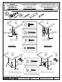
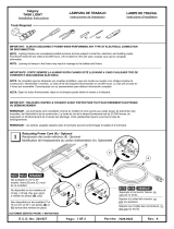
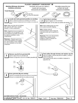
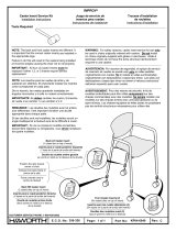
Tools Required
#2
H
A
I
G
1/8"
J
C ountertop Support Block
M ounting
Brackets
B
A
K
G
J
C ountertop
Support Block
M ounting
Brackets
Enhanced Prem ise Stackable Enhanced Prem ise M onolithic
A
C ountertop
A
C ountertop
Prem ise Stackable Prem ise M onolithic
10-12 x .75" Flat Head Screw
(H )
#10-12 x 1" Pan Head Screw
(F )
10-12 x .1" Flat Head Screw
(G )
E
F
C
B
D
L
#8-18 x .75" Self-Drilling Screw
(E )
#10-24 x .75" Self-Drilling Hex Head
(B )
#10-12 x 1" Truss Head Screw
(D )
M ounting
Brackets
M ounting
Brackets
5/16"
CUBIERTA DE M OSTRADOR
M ONOLITICA / APILABLE
PREM ISE
®
Instrucciones de Instalacion
STACKABLE M O N O LITH IC
PREM ISE
®
MONOLITHIC/STACK
COUNTER TOP
Installation Instructions
PLAN DE TRAVAIL POUR
PANNEAUX M ONOLOTHIQUES OU
SUPERPOSABLES PREM ISE
®
N otice de m ontage

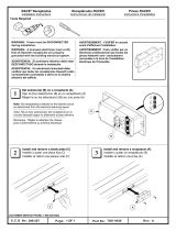
1R em ove top-cap (K )
K
2Position each m ounting bracket as show n
IM PORTANT:
For m onolitic panels only, use a shape
knife and cut the fabric over each hole location.
3U se holes in each bracket as tem plate and m ark location
Part No: Rev:
Page:
E.C.O. No: 297-063 2 O F 3 7021-7638 A
CUSTOMER SERVICE PHONE: 1-800-426-8562
CLCL
6" TYP.
C
LC
L
Prem ise Stackable Panels
Prem ise M onolithic Panels
4Install m ounting brackets
NOTE:
Be careful not to strip the screw s.
Pilot holes m aybe required.
NOTE:
R efer to page 1 to m atch hardw are to
use w ith the product.
I
K
OR
OR
6" TYP.
I
C
L
K
OR
OR
C
L
H
B
C
I
R em over la tapa superior (K) C olocar los soportes de m ontaje com o se m uestra
U sar los agujeros en los soportes com o plantilla y m arcar las
ubicaciones
R etirer la garniture supérieure (K) Placer les supports de m ontage conform ém ent aux schém as
U tiliser les trous percés dans chaque support com m e gabarits et en
m arquer l'em placem ent
IM PORTANTE:
P ara paneles m onolíticos solam ente,
use una cuchilla afilada y corte el tejido en cada
ubicación de agujero.
IM PORTANT :
Pour les panneaux m onolithiques
seulem ent, couper le tissu recouvrant chaque trou
à l'aide d'un couteau universel.
NOTA:
T e n e r c u id a d o d e n o tr a s ro s c a r lo s to rn illo s .
A gujeros pilotos pueden ser requeridos.
NOTA:
R e fe r ir s e a la h o ja 1 c a s a r lo s h e rr a je s a u s a r
con el producto.
Intalacion de los soportes de m ontaje
M onter les supports de m ontage
NOTE : V e ille r à n e p a s a b îm e r le file ta g e . Il s e p e u t
que des avant-trous soient nécessaires.
NOTE : Se reporter à la page 1 pour choisir les vis et
ferrures correspondant au produit.

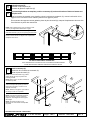
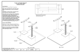
A
J
7Install countertop (A )
6U se m ounting brackets as tem plate, position countertop (A) and m ark location of holes on bottom and
d r ill p ilo t h o le s
TOP VIEW OF PANELS W ITH COUNTERTOPS
C
A
NOTE:
W hen installin g tw o o r m o re c ountertops, m ake
sure they are aligned and installed w ith no gaps.
Part No: Rev:
Page:
E.C.O. No: 297-063 3 O F 3 7021-7638 A
CUSTOMER SERVICE PHONE: 1-800-426-8562
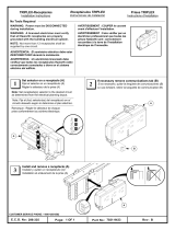
7/8"
A
NOTE:
For Enhanced Prem ise only, position
support blocks (J ) on top-cap in-line w ith
m ounting brackets.
NOTE:
R e fe r to p a g e 1 to m a tc h h a rd w a re to
u s e w ith th e p ro d u c t.
5R einstall top-cap (K )
A
K
A
G
F
Instalación de la cubierta de m ostrador (A)
R einstalar la tapa superior (K )
M onter le plan de travail (A)
R em onter la garniture supérieure (K)
U sar los soportes de m ontaje com o plantilla, colocar la cubierta de m ostrador (A ), m arcar la ubicación de los
agujeros en la cara inferior de la cubierta y barrenar los agujeros pilotos
En se servant des supports com m e gabarits, placer le plan de travail (A), m arquer l'em placem ent des trous à la
fa c e in fé rie u re e t p e rc e r d e s a v a n t-tro u s
NOTA:
Al instalar dos o m ás cubiertas, asegurarse de que
estén bien alineadas y de que no haya holguras entre ellas.
NOTE:
Lors de l'installation de deux ou trois plans de
travail, s'assurer de bien les aligner et de ne pas laisser
d'espaces entre ceux-ci.
NOTA: Para Prem ise M ejorada solam ente,
colocar los bloques de soporte (J) sobre la
tapa superior del panel y en línea con los
soportes de m ontaje.
NOTA: R e fe rirs e a la p á g in a 1 p a ra v e rific a r
los herrajes a usar con el producto.
VISTA SUPERIOR DE LOS PANELES CON LAS CUBIERTAS DE MOSTRADOR
VUE DE DESSUS DES PANNEAUX ÉQ UIPÉS DE PLANS DE TRAVAIL
NOTE:
Pour Enhanced Prem ise seulem ent,
placer les renforts (J) sur les couvercles
supérieurs, dans l'alignem ent des supports
de m ontage.
NOTE:
Se reporter à la page 1 pour
déterm iner les vis et ferrures correspondant
au produit.
-
 1
1
-
 2
2
-
 3
3


Haworth 7021-7638a Instruções de operação
- Tipo
- Instruções de operação
Artigos relacionados
-
 Haworth 7021-7640d Instruções de operação
-
 Haworth 7029-9525a Instruções de operação
-
 Haworth kp04-6405a Instruções de operação
-
 Haworth 7021-6984c Instruções de operação
-
 Haworth 7021-9433b Instruções de operação
-
 Haworth 7020-0101e Instruções de operação
-
 Haworth 7021-9436a Instruções de operação
-
 Haworth 7021-7630f Instruções de operação
-
 Haworth 7021-7642f Instruções de operação
-
 Haworth kp04-6049c Instruções de operação


