
ENGLISH
9PX8KSP
9PX10KSP
9PXEBM360SP
Installation
and user manual
Copyright © 2014 EATON
All rights reserved.
Service and support:
Call your local service representative
614-00205-01_EN

Page 2
614-00205-01_EN
SAVE THESE INSTRUCTIONS. This manual contains important instructions
that should be followed during installation and maintenance of the UPS and batteries.
The 9PX models that are covered in this manual are intended for installation
in an environment within 32 to 104°F / 0 to 40°C, free of conductive contaminant.
This equipment has been tested and found to comply with the limits for a Class A digital device,
pursuant to Part 15 of the FCC Rules. These limits are designed to provide reasonable protection against
harmful interference when the equipment is operated in a commercial environment. This equipment
generates, uses, and can radiate radio frequency energy and, if not installed and used in accordance
with the instruction manual, may cause harmful interference to radio communications. Operation of
this equipment in a residential area is likely to cause harmful interference in which case the user will
be required to correct the interference at his own expense.
Certication standards
• Safety: UL 1778 4
th
CAN/CSA C22.2 No 107.3-05, Ed.2.
• EMC: IEC/EN 62040-1 / Ed.1: 2008
IEC/EN 62040-2 / Ed.2: 2006.
FCC part 15 Class A.
• Performance: IEC/EN 62040-3 / Ed.2.0: 2011.
• IEC 61000-4-2 (ESD): level 3.
• IEC61000-4-3(Radiatedeld):level3.
• IEC 61000-4-4 (EFT): level 4.
• IEC 61000-4-5 (Fast transients): level 4.
• IEC61000-4-6(Electromagneticeld):level3.
• IEC61000-4-8(Conductedmagneticeld):level4.
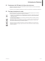
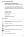
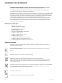
Special symbols
The following are examples of symbols used on the UPS or accessories to alert you to important
information:
RISK OF ELECTRIC SHOCK - Observe the warning associated with the risk of electric shock symbol.
Important instructions that must always be followed.
Do not discard the UPS or the UPS batteries in the trash.
This product contains sealed lead acid batteries and must be disposed as it's explain in this manual.
For more information, contact your local recycling/reuse or hazardous waste center.
This symbol indicates that you should not discard waste electrical or electronic equipment (WEEE)
in the trash. For proper disposal, contact your local recycling/reuse or hazardous waste center.
Information, advice, help.
Refer to the user manual of UPS accessories.
SAFETY INSTRUCTIONS

Page 3
614-00205-01_EN
ENGLISH
SAFETY INSTRUCTIONS
Safety of persons
• RISK OF VOLTAGE BACKFEED. The system has its own power source (the battery). Isolate the UPS
and check for hazardous voltage upstream and downstream during lockout-tagout operation.
Terminal blocks may be energized even if the system is disconnected from the AC power source.
• Dangerous voltage levels are present within the system. It should be opened exclusively by
qualiedservicepersonnel.
• The system has its own power source (the battery). Consequently, the power outlets may be
energized even if the systems is disconnected from the AC power source. Dangerous voltage levels
arepresentwithinthesystem.Itshouldbeopenedexclusivelybyqualiedservicepersonnel.
• The system must be properly grounded.
• The battery supplied with the system contains small amounts of toxic materials.
To avoid accidents, the directives listed below must be observed:
- Servicing of batteries should be performed or supervised by personnel knowledgeable about
batteries and the required precautions.
- When replacing batteries, replace with the same type and number of batteries or battery packs.
-Donotdisposeofbatteriesinare.Thebatteriesmayexplode.
- Batteries constitute a danger (electrical shock, burns). The short-circuit current may be very high.
• Precautions must be taken for all handling:
- Wear rubber gloves and boots.
- Do not lay tools or metal parts on top of batteries.
- Disconnect charging source prior to connecting or disconnecting battery terminals.
- Determine if battery is inadvertently grounded. If inadvertently grounded, remove source from
ground. Contact with any part of a grounded battery can result in electrical shock. The likelihood
of such shock can be reduced if such grounds are removed during installation and maintenance
(applicable to equipment and remote battery supplies not having a grounded supply circuit).
Product safety
• The UPS connection instructions and operation described in the manual must be followed in
the indicated order.
• CAUTION-Toreducetheriskofre,theunitconnectsonlytoacircuitprovidedwithbranchcircuit
overcurrent protection with:
- 60A rating, for 8kVA models,
- 60A rating, for 10kVA models,
in accordance with the National Electric Code, ANSI/NFPA 70.
The upstream circuit breaker must be easily accessible. The unit can be disconnected from AC
power source by opening this circuit breaker.
• A means of disconnection and overcurrent protection devices shall be provided by others for
permanently connected AC input/output circuits.
• Check that the indications on the rating plate correspond to your AC powered system and
to the actual electrical consumption of all the equipment to be connected to the system.
• For PLUGGABLE EQUIPMENT, the socket-outlet shall be installed near the equipment and shall
be easily accessible
• Never install the system near liquids or in an excessively damp environment.
• Never let a foreign body penetrate inside the system.
• Never block the ventilation grates of the system.
• Never expose the system to direct sunlight or source of heat.
• If the system must be stored prior to installation, storage must be in a dry place.
• The admissible storage temperature range is 32 to 104°F / 0 to 40ºC.
• The system is not for use in a computer room AS DEFINED IN the standard for the Protection
of Information Technology Equipment, ANSI/NFPA 75.
Contact Eaton resellers to order a special battery kit, if needed to meet the ANSI/NFPA 75
requirement.
For Model 9PX8KSP, Disconnection Device - CAUTION - A disconnect switch shall be provided by
othersforACoutputcircuit.Toreducetheriskofre,connectonlytoacircuitprovidedwithbranch
circuit overcurrent protection for 40 amperes rating in accordance with the National Electric Code.
ANSI/NFPA 70.
For Model 9PX10KSP, Disconnection Device - CAUTION - A disconnect switch shall be provided by
othersforACoutputcircuit.Toreducetheriskofre,connectonlytoacircuitprovidedwithbranch
circuit overcurrent protection for 45 amperes rating in accordance with the National Electric Code.
ANSI/NFPA 70.

Page 4
614-00205-01_EN
SAFETY INSTRUCTIONS
Special precautions
• The unit is heavy: wear safety shoes and use vacuum lifter preferentially for handling operations.
• All handling operations will require at least two people (unpacking, lifting, installation in rack
system).
• For EBM, straps are provided only for unpacking manually the unit from the carton; don’t use the
straps to carry the unit around. The unit can slip from the straps during handling (risk of injury and
product damage):
- keep 12in / 30cm minimum distance between the straps
- lift the unit carefully and keep it at low height
- keep the unit horizontal during unpacking.
• Before and after the installation, if the UPS remains de-energized for a long period, the UPS must be
energized for a period of 24 hours, at least once every 6 months (for a normal storage temperature
less than 77°F (25°C)). This charges the battery, thus avoiding possible irreversible damage.
• During the replacement of the Battery Module, it is imperative to use the same type and number of
element as the original Battery Module provided with the UPS to maintain an identical level of
performance and safety. In case of doubt, don’t hesitate to contact your EATON representative.
• All repairs and service should be performed by AUTHORIZED SERVICE PERSONNEL ONLY.
There are NO USER SERVICEABLE PARTS inside the UPS.

Page 5
614-00205-01_EN
ENGLISH
Contents
1. Introduction ....................................................................................... 6
1.1 Environmental protection ...............................................................................................6
2. Presentation ...................................................................................... 8
2.1 Weights and dimensions ...............................................................................................8
2.2 Rear panel layout ...........................................................................................................9
2.3 Accessories (optional) ....................................................................................................9
3. Installation for 9PX 8K SP and 9PX 10K SP .................................. 10
3.1 Inspecting the equipment ........................................................................................... 10
3.2 Unpacking the cabinet ................................................................................................. 10
3.3 Checking the accessory kit (9PX 8K SP/9PX 10K SP) .................................................. 11
3.4 Tower installation ......................................................................................................... 12
3.5 Rack installation .......................................................................................................... 13
3.6 Connecting the internal battery ................................................................................... 14
4. Installation for EBM(s) ................................................................... 15
4.1 Inspecting the equipment ........................................................................................... 15
4.2 Unpacking the cabinet ................................................................................................. 15
4.3 Checking the accessory kit .......................................................................................... 16
4.4 Prepare installation ...................................................................................................... 17
4.5 Tower installation .........................................................................................................18
4.6 Rack installation .......................................................................................................... 19
4.7 Connecting the EBM(s) ...............................................................................................20
4.8 Connecting other accessories ....................................................................................20
5. Power cables connection ............................................................... 21
5.1 Installation requirements .............................................................................................21
5.2 Access to terminal blocks ............................................................................................22
5.3 Hardwired Input/Output connection ............................................................................22
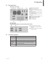
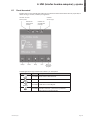
6. HMI and settings ............................................................................ 23
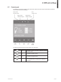
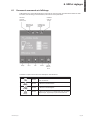
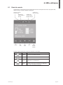
6.1 Control panel ................................................................................................................23
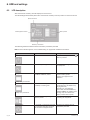
6.2 LCD description ...........................................................................................................24
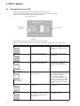
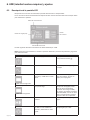
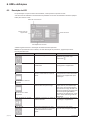
6.3 Display functions .........................................................................................................25
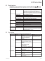
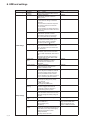
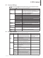
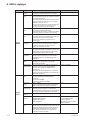
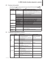
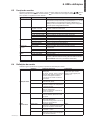
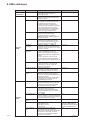
6.4 User settings ...............................................................................................................25
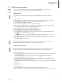
7. Operation ......................................................................................... 27
7.1 UPS startup and shutdown ..........................................................................................27
7.2 Operating modes .........................................................................................................28
7.3 Transferring the UPS between modes ......................................................................... 29
7.4 Conguring Bypass settings ........................................................................................29
7.5 Conguring battery settings ........................................................................................29
7.6 Retrieving the Event log ...............................................................................................30
7.7 Retrieving the Fault log ................................................................................................30
8. Communication .............................................................................. 31
8.1 Communication ports ..................................................................................................31
8.2 Eaton Intelligent Power Software suite .......................................................................34
9. UPS maintenance ........................................................................... 35
9.1 Equipment care ............................................................................................................35
9.2 Storing the equipment .................................................................................................35
9.3 When to replace batteries ...........................................................................................35
9.4 Replacing batteries ......................................................................................................36
9.5 Replacing the UPS equipped with a Maintenance Bypass (BPE20MBB1A) ................ 39
9.6 Recycling the used equipment ....................................................................................39
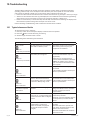
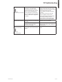
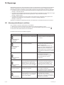
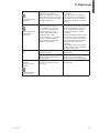
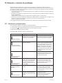
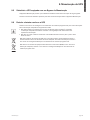
10. Troubleshooting ............................................................................. 40
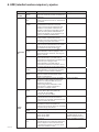
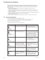
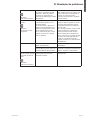
10.1 Typical alarms and faults ..............................................................................................40
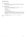
10.2 Silencing the alarm ......................................................................................................42
10.3 Service and support .....................................................................................................42
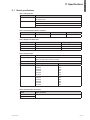
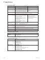
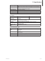
11. Specications ................................................................................ 43
11.1 Model specications .................................................................................................... 43
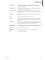
12. Glossary ......................................................................................... 47

Page 6
614-00205-01_EN
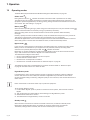
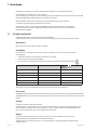
1. Introduction
Thank you for selecting an EATON product to protect your electrical equipment.
The 9PX range has been designed with the utmost care.
We recommend that you take the time to read this manual to take full advantage of the many features
of your UPS (Uninterruptible Power System).
Before installing your 9PX, please read the booklet presenting the safety instructions.
Then follow the indications in this manual.
To discover the entire range of EATON products and the options available for the 9PX range,
we invite you to visit our web site at powerquality.eaton.com or contact your EATON representative.
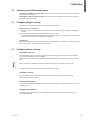
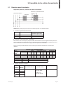
1.1 Environmental protection
EATON has implemented an environmental-protection policy.
Products are developed according to an eco-design approach.
Substances
This product does not contain CFCs, HCFCs or asbestos.
Packing
To improve waste treatment and facilitate recycling, separate the various packing components.
• The cardboard we use comprises over 50% of recycled cardboard.
• Sacks and bags are made of polyethylene.
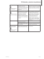
• Packingmaterialsarerecyclableandbeartheappropriateidenticationsymbol
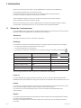
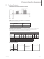
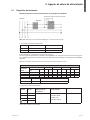
Materials Abbreviations
Number in
the symbols
Polyethylene terephthalat PET 01
High-density polyethylene HDPE 02
Polyvinyl chloride PVC 03
Low-density polyethylene LDPE 04
Polypropylene PP 05
Polystyrene PS 06
Follow all local regulations for the disposal of packing materials.
End of life
EATON will process products at the end of their service life in compliance with local regulations.
EATON works with companies in charge of collecting and eliminating our products at the end of
their service life.
Product
The product is made up of recyclable materials.
Dismantling and destruction must take place in compliance with all local regulations concerning waste.
At the end of its service life, the product must be transported to a processing center for electrical and
electronic waste.
Battery
The product contains lead-acid batteries that must be processed according to applicable local regulations
concerning batteries.
The battery may be removed to comply with regulations and in view of correct disposal.

Page 7
614-00205-01_EN
ENGLISH
1. Introduction
The Eaton® 9PX uninterruptible power system (UPS) protects your sensitive electronic equipment from
the most common power problems, including power failures, power sags, power surges, brownouts, line
noise, high voltage spikes, frequency variations, switching transients, and harmonic distortion.
Power outages can occur when you least expect it and power quality can be erratic. These power problems
have the potential to corrupt critical data, destroy unsaved work sessions, and damage hardware - causing
hours of lost productivity and expensive repairs.
With the Eaton 9PX, you can safely eliminate the effects of power disturbances and guard the integrity
of your equipment. Providing outstanding performance and reliability, the Eaton 9PX’s unique benefits
include:
• True online double-conversion technology with high power density, utility frequency independence,
and generator compatibility.
• ABM® technology that uses advanced battery management to increase battery service life,
optimize recharge time, and provide a warning before the end of useful battery life.
• Selectable High Efficiency mode of operation.
• Standard communication options: Network-MS card (Web/SNMP), one RS-232 communication
port, one USB communication port, and relay output contacts.
• Optional connectivity cards with enhanced communication capabilities (Modbus-MS, Relay-MS).
• Extended runtime with up to four Extended Battery Modules (EBMs) per UPS.
• Firmware that is easily upgradable without a service call.
• Remote On/Off control through Remote On/Off (ROO) and Remote Power Off (RPO) ports.
• Backed by worldwide agency approvals.

Page 8
614-00205-01_EN
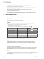
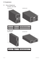
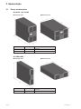
2. Presentation
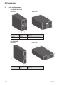
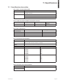
2.1 Weights and dimensions
9PX 8K SP / 9PX 10K SP
Tower installation Rack installation
Description Weights
(lb/kg)
Dimensions H x W x D
(inch/mm)
9PX8KSP 225 / 102 10.3 x 17.4 x 29.4 / 262 x 440 x 745
9PX10KSP 225 / 102 10.3 x 17.4 x 29.4 / 262 x 440 x 745
9PX EBM 360SP
Tower installation Rack installation
Description Weights
(lb/kg)
Dimensions H x W x D
(inch/mm)
9PXEBM360SP 163.2 / 74 5.2 x 17.4 x 25.4 / 130 x 440 x 645

Page 9
614-00205-01_EN
ENGLISH
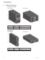
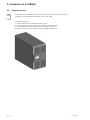
2. Presentation
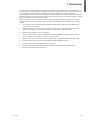
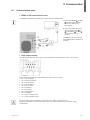
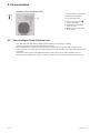
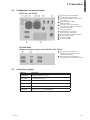
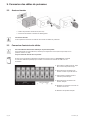
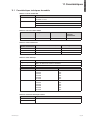
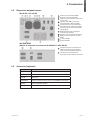
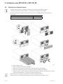
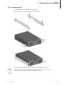
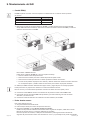
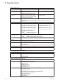
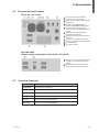
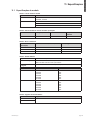
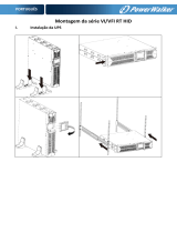
2.2 Rear panel layout
9PX 8K SP / 9PX 10K SP
1
RS232 communication port
2
USB communication port
3
Dry (relay) contacts communication
port
4
Connector for MBP and ROO (Remote
On/Off) control
5
Connectors for automatic recognition
of battery module
6
Connector for RPO (Remote Power Off)
control
7
Slot for optional communication card
8
Connector for battery module
9
Input/Output terminal blocks
10
(1) L6-30R outlet
11
(2) L14-30R outlets
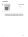
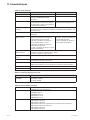
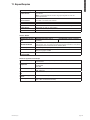
9PX EBM 360SP
(Extended Battery Module of the 9PX 8K SP and 9PX 10K SP)
12
Connectors for battery modules
(to the UPS or to the other battery
modules)
13
Connectors for automatic recognition
of battery modules
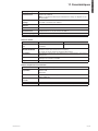
2.3 Accessories (optional)
Part number Description
9PXEBM360SP Extended Battery Module
Modbus-MS Modbus and network card
Relay-MS Relay card
BPE20MBB1A External maintenance Bypass for 9PX8KSP and 9PX10KSP
BINTSYS Battery Integration System
EBMCBL360 6 feet cable for 9PXEBM360SP

Page 10
614-00205-01_EN
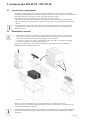
3. Installation for 9PX 8K SP and 9PX 10K SP
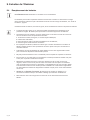
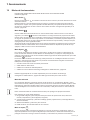
3.1 Inspecting the equipment
If any equipment has been damaged during shipment, keep the shipping cartons and packing materials
forthecarrierorplaceofpurchaseandleaclaimforshippingdamage.Ifyoudiscoverdamageafter
acceptance,leaclaimforconcealeddamage.
Toleaclaimforshippingdamageorconcealeddamage:
1. File with the carrier within 15 days of receipt of the equipment;
2. Send a copy of the damage claim within 15 days to your service representative.
Check the battery recharge date on the shipping carton label. If the date has passed and the
batteries were never recharged, do not use the UPS. Contact your service representative.
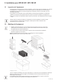
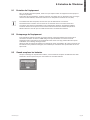
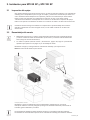
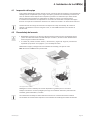
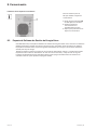
3.2 Unpacking the cabinet
• Unpacking the cabinet in a low-temperature environment may cause condensation to occur in and
on the cabinet. Do not install the cabinet until the inside and outside of the cabinet are absolutely
dry (hazard of electric shock).
• The cabinet is heavy (see "Weights and dimensions" on page 43). Follow Special precautions
provided on page 4 and on the carton.
Unpack the equipment and remove all the packing materials and shipping carton.
Note: Do not lift the UPS from the front panel.
Unpacking UPS.
Discard or recycle the packaging in a responsible manner, or store it for future use.
Placethecabinetinaprotectedareathathasadequateairowandisfreeofhumidity,ammablegas,and
corrosion.
Packing materials must be disposed of in compliance with all local regulations concerning waste.
Recycling symbols are printed on the packing materials to facilitate sorting.

Page 11
614-00205-01_EN
ENGLISH
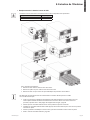
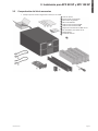
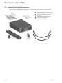
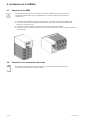
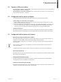
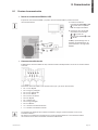
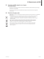
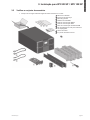
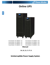
3.3 Checking the accessory kit (9PX 8K SP/9PX 10K SP)
• Verify that the following additional items are included with the UPS:
1
User manual
2
Safety instructions
3
Warranty sheet
4
Software CD-ROM
5
RS232 communication cable
6
USB communication cable
7
Network-MS communication card
8
Rack kit for 19-inch enclosures
9
Screwdriver
10
2 x internal battery pack
3. Installation for 9PX 8K SP and 9PX 10K SP

Page 12
614-00205-01_EN
3. Installation for 9PX 8K SP and 9PX 10K SP
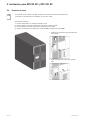
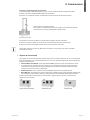
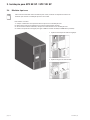
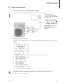
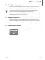
3.4 Tower installation
If you ordered other UPS accessories, refer to specific user manuals to check the tower installation
with the UPS.
To install the cabinet:
1. Place the UPS on a flat, stable surface in its final location.
2. Always keep 150 mm of free space behind the UPS rear panel.
3. If installing additional cabinets, place them next to the UPS in their final location.
4. Install mounting brackets to attach the EBM to UPS module (if EBM is present).
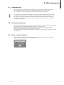
• Adjustment of the orientation of the LCD
panel and of the logo.
• Adjustment of the angle of vision of the LCD
panel.

Page 13
614-00205-01_EN
ENGLISH
3. Installation for 9PX 8K SP and 9PX 10K SP
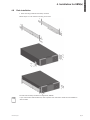
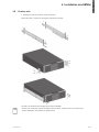
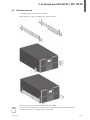
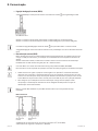
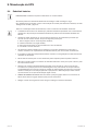
3.5 Rack installation
• Rack mounting of UPS and accessory modules.
Follow steps 1 to 4 for module mounting on the rails.
The rails and necessary hardware are supplied by EATON.
If you ordered other UPS accessories, refer to specific user manuals to check the rack installation
with the UPS.

Page 14
614-00205-01_EN
3. Installation for 9PX 8K SP and 9PX 10K SP
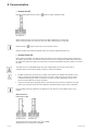
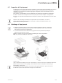
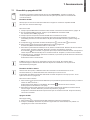
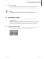
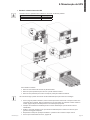
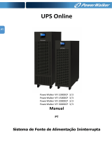
3.6 Connecting the internal battery
Do not make unauthorized changes to the UPS; otherwise, damage may occur to your equipment
and void your warranty. Do not connect the UPS to utility until installation is completed.
This step requires two service personnel, the UPS and internal battery are heavy.
Description Weights (lb/kg)
9PX 8K SP/9PX 10K SP without internal battery 91 / 41
9PX 8K SP/9PX 10K SP internal battery 67.3 / 30.5
• Mount the UPS on rack.
• Remove the center cover of the front panel.
• Remove the four screws to open the front panel.
• Remove the three screws to pull out the metal protection cover of the battery.
• Put the battery pack, screw back the metal protection cover, connect the battery and put back the
front panel, then clip the center cover.
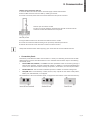
Battery connectors may be coupled
to either battery pack.
A small amount of arcing may occur when connecting the internal batteries. This is normal and will
not harm personnel. Connect the cables quickly and firmly.

Page 15
614-00205-01_EN
ENGLISH
4. Installation for EBM(s)
4.1 Inspecting the equipment
If any equipment has been damaged during shipment, keep the shipping cartons and packing materials
forthecarrierorplaceofpurchaseandleaclaimforshippingdamage.Ifyoudiscoverdamageafter
acceptance,leaclaimforconcealeddamage.
Toleaclaimforshippingdamageorconcealeddamage:
1. File with the carrier within 15 days of receipt of the equipment;
2. Send a copy of the damage claim within 15 days to your service representative.
Check the battery recharge date on the shipping carton label. If the date has passed and the
batteries were never recharged, do not use the EBM. Contact your service representative.
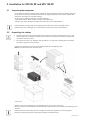
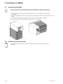
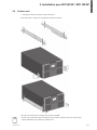
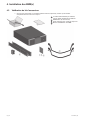
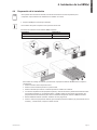
4.2 Unpacking the cabinet
• Unpacking the cabinet in a low-temperature environment may cause condensation to occur in and
on the cabinet. Do not install the cabinet until the inside and outside of the cabinet are absolutely
dry (hazard of electric shock).
• The cabinet is heavy (see "Weights and dimensions" on page 43). Follow Special precautions
provided on page 4 and on the carton.
Unpack the equipment and remove all the packing materials and shipping carton.
Note: Do not lift the EBM from the front panel.
Unpacking Extended Battery Module.
Discard or recycle the packaging in a responsible manner, or store it for future use.
Placethecabinetinaprotectedareathathasadequateairowandisfreeofhumidity,ammablegas,and
corrosion.
Packing materials must be disposed of in compliance with all local regulations concerning waste.
Recycling symbols are printed on the packing materials to facilitate sorting.

Page 16
614-00205-01_EN
4. Installation for EBM(s)
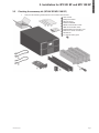
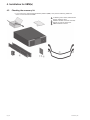
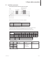
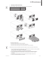
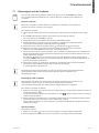
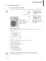
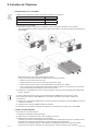
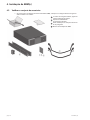
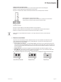
4.3 Checking the accessory kit
• If you ordered an optional Extended Battery Module (EBM), verify that the following additional
items are included with the EBM:
1
2 x Battery power cable, attached with
battery detection cable
2
Stabilizer bracket (4 screws included)
3
Rack kit for 19-inch enclosures
4
EBM Installation manual.

Page 17
614-00205-01_EN
ENGLISH
4. Installation for EBM(s)
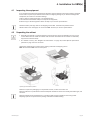
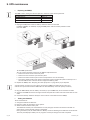
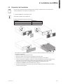
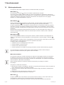
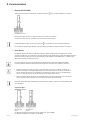
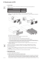
4.4 Prepare installation
If you ordered other UPS accessories, refer to specific user manuals to check the rack
installation with the UPS.
• Prepare EBM for rack mounting.
This step requires two service personnel.
The Extended Battery Module is very heavy.
Description Weights (lb/kg)
9PX EBM 360SP without internal battery 28.7 / 13
9PX EBM 360SP internal battery 67.3 / 30.5
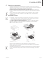
To ease its rack mounting, you can remove the battery pack from the EBM as explained below.
• Remove the center cover of the front panel.
• Remove the four screws to open the front panel.
• Remove the three screws to pull out the metal protection cover of the battery.
• Pull out the plastic handle of the left and right battery packs, and slide the packs out slowly on to a
atandstablesurface.Usetwohandstosupportthebatterypacks.Setthemasideforreinstalling
after that the EBM is rack mounted.
• Mount the EBM on rack (see "Rack installation" on page 13 ).
• Put back the battery packs, screw back the metal protection cover and the front panel, then clip the
center cover.

Page 18
614-00205-01_EN
4. Installation for EBM(s)
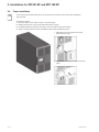
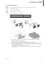
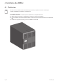
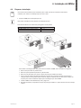
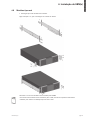
4.5 Tower installation
If you ordered other UPS accessories, refer to specific user manuals to check the tower installation
with the UPS.
To install the cabinet:
1. Place the UPS on a flat, stable surface in its final location.
2. Always keep 150 mm of free space behind the UPS rear panel.
3. If installing additional cabinets, place them next to the UPS in their final location.
4. Install mounting brackets to attach the EBM to UPS module.

Page 19
614-00205-01_EN
ENGLISH
4. Installation for EBM(s)
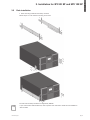
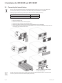
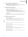
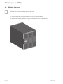
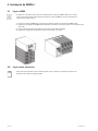
4.6 Rack installation
• Rack mounting of UPS and accessory modules.
Follow steps 1 to 4 for module mounting on the rails.
The rails and necessary hardware are supplied by EATON.
If you ordered other UPS accessories, refer to specific user manuals to check the rack installation
with the UPS.

Page 20
614-00205-01_EN
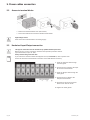
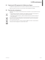
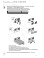
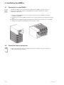
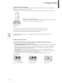
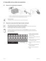
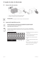
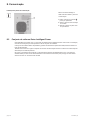
4. Installation for EBM(s)
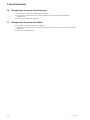
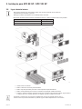
4.7 Connecting the EBM(s)
A small amount of arcing may occur when connecting an EBM to the UPS. This is normal and
will not harm personnel. Insert the EBM cable into the UPS battery connector quickly and firmly.
1. Plug the EBM power cable(s) into the battery connector(s). Up to 4 EBMs may be connected
to the UPS.
2. Verify that the EBM connections are tight and that adequate bend radius and strain relief exist for each
cable.
3. Connect the battery detection cable(s) to the connector of the UPS and of the EBM(s).
4. Check that the battery circuit breaker is switched to the “I” position (On).
4.8 Connecting other accessories
If you ordered other UPS accessories, refer to specific user manuals to check the connection
to the UPS.
A página está carregando...
A página está carregando...
A página está carregando...
A página está carregando...
A página está carregando...
A página está carregando...
A página está carregando...
A página está carregando...
A página está carregando...
A página está carregando...
A página está carregando...
A página está carregando...
A página está carregando...
A página está carregando...
A página está carregando...
A página está carregando...
A página está carregando...
A página está carregando...
A página está carregando...
A página está carregando...
A página está carregando...
A página está carregando...
A página está carregando...
A página está carregando...
A página está carregando...
A página está carregando...
A página está carregando...
A página está carregando...
A página está carregando...
A página está carregando...
A página está carregando...
A página está carregando...
A página está carregando...
A página está carregando...
A página está carregando...
A página está carregando...
A página está carregando...
A página está carregando...
A página está carregando...
A página está carregando...
A página está carregando...
A página está carregando...
A página está carregando...
A página está carregando...
A página está carregando...
A página está carregando...
A página está carregando...
A página está carregando...
A página está carregando...
A página está carregando...
A página está carregando...
A página está carregando...
A página está carregando...
A página está carregando...
A página está carregando...
A página está carregando...
A página está carregando...
A página está carregando...
A página está carregando...
A página está carregando...
A página está carregando...
A página está carregando...
A página está carregando...
A página está carregando...
A página está carregando...
A página está carregando...
A página está carregando...
A página está carregando...
A página está carregando...
A página está carregando...
A página está carregando...
A página está carregando...
A página está carregando...
A página está carregando...
A página está carregando...
A página está carregando...
A página está carregando...
A página está carregando...
A página está carregando...
A página está carregando...
A página está carregando...
A página está carregando...
A página está carregando...
A página está carregando...
A página está carregando...
A página está carregando...
A página está carregando...
A página está carregando...
A página está carregando...
A página está carregando...
A página está carregando...
A página está carregando...
A página está carregando...
A página está carregando...
A página está carregando...
A página está carregando...
A página está carregando...
A página está carregando...
A página está carregando...
A página está carregando...
A página está carregando...
A página está carregando...
A página está carregando...
A página está carregando...
A página está carregando...
A página está carregando...
A página está carregando...
A página está carregando...
A página está carregando...
A página está carregando...
A página está carregando...
A página está carregando...
A página está carregando...
A página está carregando...
A página está carregando...
A página está carregando...
A página está carregando...
A página está carregando...
A página está carregando...
A página está carregando...
A página está carregando...
A página está carregando...
A página está carregando...
A página está carregando...
A página está carregando...
A página está carregando...
A página está carregando...
A página está carregando...
A página está carregando...
A página está carregando...
A página está carregando...
A página está carregando...
A página está carregando...
A página está carregando...
A página está carregando...
A página está carregando...
A página está carregando...
A página está carregando...
A página está carregando...
A página está carregando...
A página está carregando...
A página está carregando...
A página está carregando...
A página está carregando...
A página está carregando...
A página está carregando...
A página está carregando...
A página está carregando...
A página está carregando...
A página está carregando...
A página está carregando...
A página está carregando...
A página está carregando...
A página está carregando...
A página está carregando...
A página está carregando...
A página está carregando...
A página está carregando...
A página está carregando...
A página está carregando...
A página está carregando...
A página está carregando...
A página está carregando...
A página está carregando...
A página está carregando...
A página está carregando...
A página está carregando...
A página está carregando...
A página está carregando...
A página está carregando...
A página está carregando...
A página está carregando...
-
 1
1
-
 2
2
-
 3
3
-
 4
4
-
 5
5
-
 6
6
-
 7
7
-
 8
8
-
 9
9
-
 10
10
-
 11
11
-
 12
12
-
 13
13
-
 14
14
-
 15
15
-
 16
16
-
 17
17
-
 18
18
-
 19
19
-
 20
20
-
 21
21
-
 22
22
-
 23
23
-
 24
24
-
 25
25
-
 26
26
-
 27
27
-
 28
28
-
 29
29
-
 30
30
-
 31
31
-
 32
32
-
 33
33
-
 34
34
-
 35
35
-
 36
36
-
 37
37
-
 38
38
-
 39
39
-
 40
40
-
 41
41
-
 42
42
-
 43
43
-
 44
44
-
 45
45
-
 46
46
-
 47
47
-
 48
48
-
 49
49
-
 50
50
-
 51
51
-
 52
52
-
 53
53
-
 54
54
-
 55
55
-
 56
56
-
 57
57
-
 58
58
-
 59
59
-
 60
60
-
 61
61
-
 62
62
-
 63
63
-
 64
64
-
 65
65
-
 66
66
-
 67
67
-
 68
68
-
 69
69
-
 70
70
-
 71
71
-
 72
72
-
 73
73
-
 74
74
-
 75
75
-
 76
76
-
 77
77
-
 78
78
-
 79
79
-
 80
80
-
 81
81
-
 82
82
-
 83
83
-
 84
84
-
 85
85
-
 86
86
-
 87
87
-
 88
88
-
 89
89
-
 90
90
-
 91
91
-
 92
92
-
 93
93
-
 94
94
-
 95
95
-
 96
96
-
 97
97
-
 98
98
-
 99
99
-
 100
100
-
 101
101
-
 102
102
-
 103
103
-
 104
104
-
 105
105
-
 106
106
-
 107
107
-
 108
108
-
 109
109
-
 110
110
-
 111
111
-
 112
112
-
 113
113
-
 114
114
-
 115
115
-
 116
116
-
 117
117
-
 118
118
-
 119
119
-
 120
120
-
 121
121
-
 122
122
-
 123
123
-
 124
124
-
 125
125
-
 126
126
-
 127
127
-
 128
128
-
 129
129
-
 130
130
-
 131
131
-
 132
132
-
 133
133
-
 134
134
-
 135
135
-
 136
136
-
 137
137
-
 138
138
-
 139
139
-
 140
140
-
 141
141
-
 142
142
-
 143
143
-
 144
144
-
 145
145
-
 146
146
-
 147
147
-
 148
148
-
 149
149
-
 150
150
-
 151
151
-
 152
152
-
 153
153
-
 154
154
-
 155
155
-
 156
156
-
 157
157
-
 158
158
-
 159
159
-
 160
160
-
 161
161
-
 162
162
-
 163
163
-
 164
164
-
 165
165
-
 166
166
-
 167
167
-
 168
168
-
 169
169
-
 170
170
-
 171
171
-
 172
172
-
 173
173
-
 174
174
-
 175
175
-
 176
176
-
 177
177
-
 178
178
-
 179
179
-
 180
180
-
 181
181
-
 182
182
-
 183
183
-
 184
184
-
 185
185
-
 186
186
-
 187
187
-
 188
188
-
 189
189
-
 190
190
-
 191
191
-
 192
192


Eaton 9PX10KSP Installation and User Manual
- Tipo
- Installation and User Manual
- Este manual também é adequado para
em outras línguas
- español: Eaton 9PX10KSP
- français: Eaton 9PX10KSP
- English: Eaton 9PX10KSP
Artigos relacionados
-
Eaton Pulsar M 3000 RT 2U, Bundle Manual do usuário
-
-
-
-
-
-
-
-
-
Outros documentos
-
 PowerWalker VI 1500 RT HID Manual do proprietário
-
PowerWalker Basic VI 850 SB UK Manual do proprietário
-
 Power Walker VFI 15000CP 3/3 Manual do usuário
-
 PowerWalker VFI 20000 CP 3/3 BI Manual do proprietário
-
Approx APPUPS9 Especificação
-
Jackery JE-300B Manual do usuário
-
Samsung DW60A8060FS Guia de usuario
-
Bay Networks BayStack UPS45 Manual do usuário
-
Chloride Desk POWER 650 Ficha de dados
-
MGE UPS Systems 2200 RT 2U Manual do usuário


