
Effective September 2013
En vigueur en septembre 2013
Vigente a partir de septiembre de 2013
Instructional Leaet IL003002EN
Notice d’instructions IL003002EN
Folleto de instrucción IL003002EN
Mechanical interlock kit BRMIKCSR installation instructions
Instructions d’installation du kit de verrouillage mécanique BRMIKCSR
Instrucciones de instalación del juego de enclavamiento mecánico BRMIKCSR
Read all instructions before beginning
installation of this product.
Materials needed
(not included)
•
Drill
•
3/16-inch drill bit
•
5/32-inch drill bit
•
5/16-inch nut driver
•
File or de-burring tool
•
Medium Phillips screwdriver
•
Two-pole BR breaker—sized accordingly
to generator
Parts list
(A) Mechanical interlock assembly with slider
plate (quantity 1)
(B) 10–32 x 1/4-inch screws (quantity 4)
(C) 10–32 x 3/16-inch screws (quantity 4)
(D) Mechanically interlocked breaker label
(E) Operating instructions for generator power
label (yellow)
(F) Generator hold-down retainer (quantity 1)
(G) #5–20 x 2 7/8-inch breaker hold-down
screw (quantity 1)
DANGER
HAZARDOUS VOLTAGE. CAN CAUSE SEVERE
INJURY OR DEATH. TURN OFF OR DISCONNECT
THE POWER SUPPLYING THE LOADCENTER
WHERE THE MECHANICAL INTERLOCK KIT
WILL BE INSTALLED. THIS MAY REQUIRE THAT
YOU CONTACT YOUR LOCAL ELECTRIC UTILITY
TO DISCONNECT POWER TO AN EXISTING
LOADCENTER. THE LINE SIDE OF THE MAIN
BREAKER IS ENERGIZED UNLESS POWER IS
DISCONNECTED UPSTREAM.
Lire toutes les instructions avant de procéder
à l’installation de ce produit.
Matériel nécessaire
(non fourni)
•
Perceuse
•
Foret de 3/16 po
•
Foret de 5/32 po
•
Tourne-écrou de 5/16 po
•
Lime ou outil d’ébavurage
•
Tournevis Phillips moyen
•
Disjoncteur BR bipolaire — de calibre
adapté au groupe électrogène
Liste des pièces
(A) Verrou mécanique à plaque coulissante
(quantité 1)
(B) Vis de 10–32 x 1/4 pouce (quantité 4)
(C) Vis de 10–32 x 3/16 pouce (quantité 4)
(D) Étiquette disjoncteur à verrouillage
mécanique
(E) Étiquette d’instructions pour alimentation
par groupe électrogène (jaune)
(F) Attache de retenue pour disjoncteur de
groupe électrogène (quantité 1)
(G) Vis de retenue de disjoncteur
n° 5-20 x 2-7/8 pouces (quantité 1)
DANGER
TENSION DANGEREUSE. PEUT PROVOQUER DES
BLESSURES GRAVES OU LA MORT. COUPER OU
DÉBRANCHER L’ALIMENTATION ÉLECTRIQUE DU
PANNEAU DE DISTRIBUTION OÙ LE SYSTÈME
DE VERROUILLAGE MECANIQUE DOIT ÊTRE
INSTALLÉ. IL PEUT ÊTRE NÉCESSAIRE DE
DEMANDER À LA COMPAGNIE D’ÉLECTRICITÉ
LOCALE DE COUPER L’ALIMENTATION D’UN
PANNEAU DE DISTRIBUTION EXISTANT. LE CÔTÉ
SECTEUR DU DISJONCTEUR EST SOUS TENSION
TANT QUE L’ALIMENTATION N’A PAS ÉTÉ COUPÉE
EN AMONT.
Lea todas las instrucciones antes de
comenzar con la instalación de este producto.
Materiales necesarios
(no incluidos)
•
Taladro
•
Broca de 4.8 mm (3/16 pulg.)
•
Broca de 4 mm (5/32 pulg.)
•
Llave para tuercas de 8 mm (5/16 pulg.)
•
Lija o herramienta para quitar rebabas
•
Destornillador Phillips mediano
•
Interruptor bipolar tipo BR de tamaño
acorde con el generador
Lista de piezas
(A) Conjunto de enclavamiento mecánico con
placa deslizante (cant. 1)
(B) Tornillos N.° 10–32 x 1/4 pulg. (cant. 4)
(C) Tornillos N.° 10–32 x 3/16 (cant. 4)
(D) Etiqueta del interruptor de enclavamiento
mecánico
(E) Instrucciones de funcionamiento
de la etiqueta del generador de energía
eléctrica (amarillo)
(F) Enganche de sujeción del generador
(cant. 1)
(G) Tornillo de sujeción del interruptor
N.º 5–20 x 2 7/8 pulg. (cant. 1)
PELIGRO
VOLTAJE PELIGROSO. PUEDE CAUSAR LESIONES
GRAVES O LA MUERTE. APAGUE O DESCONECTE
EL SUMINISTRO DE ENERGÍA ELÉCTRICA AL
CENTRO DE CARGA DONDE SE INSTALARÁ EL
JUEGO DE ENCLAVAMIENTO MECÁNICO. ES
POSIBLE QUE DEBA COMUNICARSE CON SU
EMPRESA DE SERVICIO ELÉCTRICO LOCAL PARA
DESCONECTAR LA ENERGÍA DE UN CENTRO DE
CARGA. EL LADO DE LA LÍNEA DEL INTERRUPTOR
PRINCIPAL ESTÁ ENERGIZADO, A MENOS QUE LA
ENERGÍA ELÉCTRICA SE DESCONECTE DE ARRIBA.

Instructional Leaet IL003002EN
Effective September 2013
Mechanical interlock kit BRMIKCSR
installation instructions
EATON www.eaton.com
IMPORTANT
THIS PRODUCT MUST BE INSTALLED IN ACCORDANCE
WITH THE NATIONAL ELECTRICAL CODET (NECT) AND
ANY APPLICABLE LOCAL CODE. BEFORE INSTALLING
EQUIPMENT, CHECK WITH YOUR LOCAL ELECTRICAL
INSPECTOR FOR REQUIREMENTS AND INFORMATION.
IF YOU HAVE ANY QUESTIONS OR NEED ASSISTANCE,
CONTACT A QUALIFIED ELECTRICAL PROFESSIONAL.
EATON STRONGLY RECOMMENDS THAT THIS
PRODUCT BE INSTALLED BY A QUALIFIED ELECTRICAL
PROFESSIONAL.
Installation instructions
Step 1
Verify power at the loadcenter is off before
beginning installation.
DANGER
TURN OFF OR DISCONNECT THE POWER SUPPLYING
THE PANEL WHERE THE MECHANICAL INTERLOCK
KIT WILL BE INSTALLED. THIS MAY REQUIRE THAT
YOU CONTACT YOUR LOCAL ELECTRIC UTILITY TO
DISCONNECT POWER TO AN EXISTING LOADCENTER.
THE LINE SIDE OF THE MAIN BREAKER IS ENERGIZED
UNLESS POWER IS DISCONNECTED UPSTREAM.
Step 2
Remove the trim/door from the enclosure by
removing all screws attaching the trim/door
to the enclosure. Keep screws to re-attach
trim/door after installation.
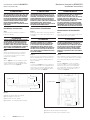
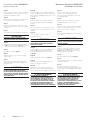
Step 3
Refer to Figure 1 and locate hold-down retainer
over rectangular hole in interior backpan and
outside of main bus. (Locate at upper-most bus
stab location as shown in Figure 2.)
d
Rectangular Hole
b
Push Here
c
Retainer
a
Main Bus
Figure 1.
a
Main Bus / Bus principal / Barra colectora principal
b
Push Here / Appuyer ici / Presione aquí
c
Retainer / Attache de retenue / Enganche
d
Rectangular Hole / Trou rectangulaire / Orificio rectangular
Hold-Down Retainer
b
Main Breaker
a
Figure 2.
a
Main Breaker / Disjoncteur principal / Interruptor principal
b
Hold-Down Retainer / Attache de retenue / Enganche de sujeción
IMPORTANT
CE PRODUIT DOIT ÊTRE INSTALLÉ CONFORMÉMENT AU
CODE NATIONAL DE L’ÉLECTRICITÉ (CCE, NECT) ET À
TOUT CODE LOCAL EN VIGUEUR. AVANT D’INSTALLER
LE MATÉRIEL, SE RENSEIGNER SUR LES EXIGENCES ET
AUTRES INFORMATIONS AUPRÈS DE L’INSPECTEUR
EN ÉLECTRICITÉ LOCAL. POUR TOUTE QUESTION OU
BESOIN D’ASSISTANCE, S’ADRESSER À UN ÉLECTRICIEN
PROFESSIONNEL QUALIFIÉ. EATON CONSEILLE
FORTEMENT DE FAIRE INSTALLER CE PRODUIT PAR UN
ÉLECTRICIEN PROFESSIONNEL QUALIFIÉ.
Instructions d’installation
Étape 1
Vérifier que l’alimentation électrique du panneau
de distribution est coupée avant de procéder à
l’installation.
DANGER
COUPER OU DÉBRANCHER L’ALIMENTATION
ÉLECTRIQUE DU PANNEAU OÙ LE SYSTÈME DE
VERROUILLAGE MECANIQUE DOIT ÊTRE INSTALLÉ.
IL PEUT ÊTRE NÉCESSAIRE DE DEMANDER À LA
COMPAGNIE D’ÉLECTRICITÉ LOCALE DE COUPER
L’ALIMENTATION D’UN PANNEAU DE DISTRIBUTION
EXISTANT. LE CÔTÉ SECTEUR DU DISJONCTEUR EST
SOUS TENSION TANT QUE L’ALIMENTATION N’A PAS
ÉTÉ COUPÉE EN AMONT.
Étape 2
Retirer toutes les vis de fixation pour déposer le
panneau d’habillage/la porte. Conserver les vis
pour remonter le panneau d’habillage/la porte
après l’installation.
Étape 3
Se reporter à la Figure 1 et trouver l’attache de
retenue au-dessus du trou rectangulaire dans le
fond intérieur et à l’extérieur du bus principal
(situé à l’emplacement du stabilisateur de bus
le plus haut, comme à la Figure 2).
IMPORTANTE
ESTE PRODUCTO DEBE INSTALARSE DE ACUERDO CON
EL CÓDIGO ELÉCTRICO NACIONAL ESTADOUNIDENSE
(NATIONAL ELECTRICAL CODET, NECT) Y LOS
CÓDIGOS LOCALES APLICABLES. ANTES DE INSTALAR
EL EQUIPO, CONSULTE LOS REQUISITOS Y LA
INFORMACIÓN CON SU INSPECTOR DE ELECTRICIDAD
LOCAL. SI TIENE PREGUNTAS O NECESITA
ASISTENCIA, COMUNÍQUESE CON UN PROFESIONAL
DE ELECTRICIDAD CALIFICADO. EATON RECOMIENDA
AMPLIAMENTE QUE ESTE PRODUCTO SEA INSTALADO
POR UN PROFESIONAL DE ELECTRICIDAD CALIFICADO.
Instrucciones de instalación
Paso 1
Antes de comenzar con la instalación, desconecte
la alimentación del centro de carga.
PELIGRO
APAGUE O DESCONECTE EL SUMINISTRO DE ENERGÍA
ELÉCTRICA AL PANEL DONDE SE INSTALARÁ EL JUEGO
DE ENCLAVAMIENTO MECÁNICO. ES POSIBLE QUE
DEBA COMUNICARSE CON SU EMPRESA DE SERVICIO
ELÉCTRICO LOCAL PARA DESCONECTAR LA ENERGÍA
DE UN CENTRO DE CARGA. EL LADO DE LA LÍNEA
DEL INTERRUPTOR PRINCIPAL ESTÁ ENERGIZADO, A
MENOS QUE LA ENERGÍA ELÉCTRICA SE DESCONECTE
DE ARRIBA.
Paso 2
Retire la tapa del receptáculo quitando todos los
tornillos que la ajustan. Guarde los tornillos para
volver a ajustar la tapa luego de la instalación.
Paso 3
Consulte la Figura 1 y coloque el enganche
de sujeción sobre el orificio rectangular de la
placa de montaje interior y fuera de la barra
colectora principal. (Colóquelo tan arriba de la
barra colectora como sea posible, como se
muestra en la Figura 2).
2

Instructional Leaet IL003002EN
Effective September 2013
Mechanical interlock kit BRMIKCSR
installation instructions
EATON www.eaton.com
Step 4
Snap in end of generator hold-down retainer at
interior backpan by pushing downward. It will
automatically locate in pan.
Step 5
Install generator breaker onto bus.
WARNING
DO NOT SCRATCH, NICK, BEND, OR OTHERWISE
DAMAGE BUS OR BACKPAN. BENT BUS OR BACKPAN
CAN CAUSE IMPROPER CONNECTION OF BREAKERS,
WHICH CAN LEAD TO PRODUCT FAILURE, PROPERTY
DAMAGE, OR PERSONAL INJURY. CLEAR AWAY ANY
LOOSE METAL SHAVINGS. METAL SHAVINGS LEFT IN
THE PANEL FROM DRILLING, DE-BURRING, ETC. CAN
CAUSE PRODUCT FAILURE, PROPERTY DAMAGE, OR
PERSONAL INJURY.
Step 6
Insert provided (G) screw into hole in generator
breaker. Thread into hold-down retainer and
tighten.
ote:N Torque screw to 13 in-lbs. Do not
overtighten.
Trim/doors with pre-installed drill points only
ote:N If you panel does not have pre-installed drill
points, please skip to Step 13.
Step 7
Place the trim/door on a firm surface with the
front of the trim/door facing down.
ote:N Verify there is enough open space below
the drill point locations to allow for the drill bit to
completely go through the trim/door. Make sure
the door is in the open position.
Step 8
With the trim/door held securely on the surface,
locate the four drill points. Use a 3/16-inch drill
bit to drill out the mounting holes at the drill
point locations.
CAUTION
BURRS MAY BE SHARP. USE PROPER PERSONAL
PROTECTION EQUIPMENT WHILE REMOVING BURRS.
Étape 4
Appuyer sur l’extrémité de l’attache de retenue
de disjoncteur de groupe pour l’encliqueter sur le
fond intérieur. Elle se positionne automatiquement
dans la plaque de fond.
Étape 5
Installer le disjoncteur de groupe électrogène sur
le bus.
AVERTISSEMENT
NE PAS RAYER, ENTAILLER, DÉFORMER NI AUTREMENT
ENDOMMAGER LE BUS OU LA PLAQUE DE FOND. LA
DÉFORMATION DU BUS OU DU FOND PEUT PROVOQUER
DE MAUVAIS CONTACTS DES DISJONCTEURS,
POUVANT ENTRAÎNER UNE DÉFAILLANCE DE PRODUIT,
DES DÉGÂTS MATÉRIELS OU DES BLESSURES
CORPORELLES. ÉLIMINER TOUS LES COPEAUX
MÉTALLIQUES. LES COPEAUX MÉTALLIQUES ISSUS
DU PERÇAGE, DE L’ÉBAVURAGE, ETC. ET LAISSÉS
DANS LE PANNEAU PEUVENT PROVOQUER UNE
DÉFAILLANCE DE PRODUIT, DES DÉGÂTS MATÉRIELS
OU DES BLESSURES CORPORELLES.
Étape 6
Insérer la vis (G) fournie dans le trou du
disjoncteur de groupe électrogène. Visser dans
l’attache de retenue et serrer.
emarque :R Serrer la vis à un couple de 1,5 Nm
(13 po-lb). Ne pas forcer.
Panneaux d’habillage/de porte à points de
perçage préexistants seulement
emarque :R Si le panneau ne comporte pas
de points de perçage préexistants, passer
directement à l’étape 13.
Étape 7
Placer le panneau d’habillage/la porte sur une
surface ferme, face avant vers le bas.
emarque :R Vérifier qu’il y a suffisamment
d’espace libre sous les points de perçage pour
permettre au foret de traverser complètement
le panneau d’habillage/la porte. S’assurer que la
porte est en position ouverte.
Étape 8
Le panneau d’habillage/de porte étant solidement
maintenu sur la surface, localiser les quatre points
de perçage. À l’aide d’un foret de 3/16 pouce,
percer les trous de fixation aux points de perçage.
ATTENTION
LES BAVURES PEUVENT ÊTRE COUPANTES. UTILISER
UN ÉQUIPEMENT DE PROTECTION INDIVIDUELLE
ADAPTÉ POUR ÉBAVURER.
Paso 4
Encaje el borde del enganche de sujeción
del generador en la placa de montaje
interior presionando hacia abajo. Se ubicará
automáticamente en la placa.
Paso 5
Instale el interruptor del generador en la
barra colectora.
ADVERTENCIA
NO RAYE, CORTE, DOBLE O DAÑE LA BARRA
COLECTORA O LA PLACA DE MONTAJE. SI LA BARRA
COLECTORA O LA PLACA DE MONTAJE ESTÁN
DOBLADAS, PUEDEN PRODUCIR UNA CONEXIÓN
INADECUADA DE LOS INTERRUPTORES, LO QUE
PUEDE OCASIONAR FALLAS EN EL PRODUCTO,
DAÑOS A LA PROPIEDAD O LESIONES PERSONALES.
ELIMINE LAS VIRUTAS METÁLICAS SUELTAS. LAS
VIRUTAS METÁLICAS SUELTAS EN EL PANEL, DEBIDO
A LA ACCIÓN DEL TALADRO O LA HERRAMIENTA
PARA QUITAR REBABAS, ETC., PUEDEN OCASIONAR
FALLAS EN EL PRODUCTO, DAÑOS A LA PROPIEDAD O
LESIONES PERSONALES.
Paso 6
Inserte el tornillo (G) provisto en el orificio
del interruptor del generador. Colóquelo en el
enganche de sujeción y apriete.
ota:N Apriete los tornillos a 1.46 Nm (13 lb.-pulg.).
No apriete los tornillos en exceso.
Únicamente para tapas con puntos de
perforación instalados previamente
ota:N Si su panel no tiene puntos de perforación
instalados previamente, diríjase al Paso 13.
Paso 7
Coloque la tapa sobre una superficie firme con la
parte frontal de la placa hacia abajo.
ota:N Verifique que quede la apertura suficiente
debajo de los puntos de perforación para
que la broca pueda atravesar por completo
la tapa. Asegúrese de que la tapa esté en la
posición abierta.
Paso 8
Con la tapa colocada en forma segura sobre
la superficie, ubique los cuatro puntos de
perforación. Utilice una broca de 4.8 mm
(3/16 pulg.) para perforar los orificios de montaje
en los puntos de perforación.
PRECAUCIÓN
LAS REBABAS PUEDEN SER FILOSAS. UTILICE EL
EQUIPO DE PROTECCIÓN PERSONAL ADECUADO PARA
QUITAR LAS REBABAS.
3

Instructional Leaet IL003002EN
Effective September 2013
Mechanical interlock kit BRMIKCSR
installation instructions
EATON www.eaton.com
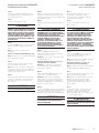
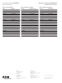
Step 9
Install the mechanical interlock assembly with
four (B) screws according to Figure 3 by installing
screws from the back side of the trim/door.
ote:N Interlock assembly will not attach correctly
if screws are not installed from the back side of
the trim/door.
Step 10
Place labels according to Figure 5.
Step 11
Re-attach trim/door to the enclosure using the
original screws.
Step 12
Confirm interlock prevents main breaker and
generator breaker from being in the ON position
at the same time.
WARNING
BEFORE ENERGIZING LOADCENTER, RE-CHECK ALL
ELECTRICAL CONNECTIONS AFTER ALL WIRING
HAS BEEN COMPLETED AND BREAKERS HAVE BEEN
INSTALLED IN THE LOADCENTER. INCORRECT WIRING
CAN CAUSE PRODUCT FAILURE, PROPERTY DAMAGE,
OR PERSONAL INJURY.
Trim/doors without pre-installed drill points only
Step 13
Place inner trim/door on a firm surface with the
front of the trim/door facing down.
Step 14
Mount the interlock assembly to the trim/door
according to Figure 4 with four (B) screws by
installing screws from the back side of the trim/
door through the main breaker opening.
Figure 3. With Pre-Installed Drill Points Only /
Points de perçage préexistants seulement /
Únicamente para tapas con puntos de
perforación instalados previamente
Figure 4. Without Pre-Installed Drill Points
Only / Pas de points de perçage préexistants
seulement / Únicamente para tapas sin puntos
de perforación instalados previamente
Figure 5.
Étape 9
Installer le système de verrou mécanique avec
quatre vis (B) posées depuis la face arrière
du panneau d’habillage/de porte comme sur
la Figure 3.
emarque :R Le système de verrouillage ne
s’attache pas correctement si les vis ne
sont pas posées depuis l’arrière du panneau
d’habillage/de porte.
Étape 10
Apposer les étiquettes comme sur la Figure 5.
Étape 11
Remonter le panneau d’habillage/la porte sur
l’armoire à l’aide des vis d’origine.
Étape 12
Vérifier que le verrou empêche le disjoncteur
principal et le disjoncteur de groupe électrogène
d’être en position de marche (ON) en même
temps.
AVERTISSEMENT
AVANT DE REMETTRE LE PANNEAU DE
DISTRIBUTION SOUS TENSION, REVÉRIFIER TOUS
LES RACCORDEMENTS ÉLECTRIQUES UNE FOIS QUE
TOUS LES CÂBLAGES SONT TERMINÉS ET QUE LES
DISJONCTEURS SONT INSTALLÉS DANS LE PANNEAU
DE DISTRIBUTION. UN CÂBLAGE INCORRECT PEUT
PROVOQUER UNE DÉFAILLANCE DE PRODUIT,
DES DÉGÂTS MATÉRIELS OU DES BLESSURES
CORPORELLES.
Panneaux d’habillage/de porte sans points
de perçage préexistants seulement
Étape 13
Placer l’habillage intérieur/la porte sur une surface
ferme, face avant vers le bas.
Étape 14
Monter le système de verrou mécanique sur
le panneau d’habillage/de porte comme sur la
Figure 4 avec quatre vis (B) posées depuis
la face arrière du panneau à travers l’ouverture
de disjoncteur principal.
Paso 9
Instale el juego de enclavamiento mecánico
con cuatro tornillos (B) según se indica en la
Figura 3 a través de la instalación de tornillos
en la parte posterior de la tapa.
ota:N El conjunto de enclavamiento no se ajustará
correctamente si los tornillos no son instalados en
la parte posterior de la tapa.
Paso 10
Coloque las etiquetas según la Figura 5.
Paso 11
Vuelva a ajustar la tapa en el receptáculo utilizando
los tornillos originales.
Paso 12
Confirmar que el enclavamiento evitará que el
interruptor principal y el interruptor del generador
estén en la posición ON (ENCENDIDO) al mismo
tiempo.
ADVERTENCIA
ANTES DE SUMINISTRAR ENERGÍA ELÉCTRICA AL
CENTRO DE CARGA, VUELVA A VERIFICAR TODAS
LAS CONEXIONES ELÉCTRICAS LUEGO DE QUE
SE HA REALIZADO TODO EL CABLEADO Y LOS
INTERRUPTORES SE HAN INSTALADO EN EL CENTRO
DE CARGA. EL CABLEADO INCORRECTO PUEDE
PRODUCIR FALLAS EN EL PRODUCTO, DAÑOS A LA
PROPIEDAD O LESIONES PERSONALES.
Únicamente para tapas sin puntos de
perforación instalados previamente
Paso 13
Coloque la tapa interna sobre una superficie firme
con la parte frontal de la placa hacia abajo.
Paso 14
Instale el conjunto de enclavamiento mecánico en
la tapa como se muestra en la Figura 4 con cuatro
tornillos (B), colocando los tornillos en la parte
posterior de la tapa a través de la apertura del
interruptor principal.
4

Instructional Leaet IL003002EN
Effective September 2013
Mechanical interlock kit BRMIKCSR
installation instructions
EATON www.eaton.com
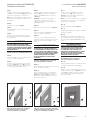
Step 15
Use the four hole locations on the mounting plate
as a drill bit guide to drill four pilot holes in the
trim/door with a 5/32-inch drill bit.
Step 16
Remove the mechanical interlock assembly from
the trim/door by removing all four screws.
Step 17
Drill the four mounting hole locations by using
a 3/16-inch drill bit on the four pilot holes created
in Step 15.
Step 18
File or de-burr the newly created mounting holes.
CAUTION
BURRS MAY BE SHARP. USE PROPER PERSONAL
PROTECTION EQUIPMENT WHILE REMOVING BURRS.
Step 19
Install the mechanical interlock assembly with
four (B) screws according to Figure 3 by installing
screws from the back side of the trim/door.
Step 20
Place label according to Figure 5.
Step 21
Re-attach trim/door to the enclosure using the
original screws.
Step 22
Confirm interlock prevents main breaker and
generator breaker from being in the ON position
at the same time.
WARNING
BEFORE ENERGIZING LOADCENTER, RE-CHECK ALL
ELECTRICAL CONNECTIONS AFTER ALL WIRING
HAS BEEN COMPLETED AND BREAKERS HAVE BEEN
INSTALLED IN THE LOADCENTER. INCORRECT WIRING
CAN CAUSE PRODUCT FAILURE, PROPERTY DAMAGE,
OR PERSONAL INJURY.
Étape 15
Utiliser les quatre trous de la plaque de fixation
en guise de gabarit pour percer quatre avant-trous
dans le panneau d’habillage/de porte avec un foret
de 5/32 pouce.
Étape 16
Retirer les quatre vis pour déposer le système
de verrou mécanique du panneau d’habillage/
de porte.
Étape 17
Percer les quatre trous de fixation avec un foret
de 3/16 pouce sur les quatre avant-trous créés à
l’étape 15
Étape 18
Limer ou ébavurer les trous de fixation
nouvellement percés.
ATTENTION
LES BAVURES PEUVENT ÊTRE COUPANTES. UTILISER
UN ÉQUIPEMENT DE PROTECTION INDIVIDUELLE
ADAPTÉ POUR ÉBAVURER.
Étape 19
Installer le système de verrou mécanique avec
quatre vis (B) posées depuis la face arrière
du panneau d’habillage/de porte comme sur
la Figure 3.
Étape 20
Apposer l’étiquette comme sur la Figure 5.
Étape 21
Remonter le panneau d’habillage/la porte sur
l’armoire à l’aide des vis d’origine.
Étape 22
Vérifier que le verrou empêche le disjoncteur
principal et le disjoncteur de groupe électrogène
d’être en position de marche (ON) en même temps.
AVERTISSEMENT
AVANT DE REMETTRE LE PANNEAU DE
DISTRIBUTION SOUS TENSION, REVÉRIFIER TOUS
LES RACCORDEMENTS ÉLECTRIQUES UNE FOIS QUE
TOUS LES CÂBLAGES SONT TERMINÉS ET QUE LES
DISJONCTEURS SONT INSTALLÉS DANS LE PANNEAU
DE DISTRIBUTION. UN CÂBLAGE INCORRECT PEUT
PROVOQUER UNE DÉFAILLANCE DE PRODUIT, DES
DÉGÂTS MATÉRIELS OU DES BLESSURES CORPORELLES.
Paso 15
Utilice los cuatro orificios en la placa de
montaje como una guía para perforar los
cuatro orificios piloto de la tapa con una broca
de 4 mm (5/32 pulg.).
Paso 16
Retire el conjunto de enclavamiento mecánico
de la tapa, quitando los cuatro tornillos.
Paso 17
Perfore los cuatro orificios de montaje utilizando
una broca de 4.8 mm (3/16 pulg.) en los cuatro
orificios piloto creados en el Paso 15.
Paso 18
Lije o extraiga las rebabas de los nuevos orificios
de montaje.
PRECAUCIÓN
LAS REBABAS PUEDEN SER FILOSAS. UTILICE EL
EQUIPO DE PROTECCIÓN PERSONAL ADECUADO PARA
QUITAR LAS REBABAS.
Paso 19
Instale el conjunto de enclavamiento mecánico
con cuatro tornillos (B) según se indica en la
Figura 3 a través de la instalación de tornillos
en la parte posterior de la tapa.
Paso 20
Coloque la etiqueta siguiendo la Figura 5.
Paso 21
Vuelva a ajustar la tapa en el receptáculo utilizando
los tornillos originales.
Paso 22
Confirmar el enclavamiento evitará que el
interruptor principal y el interruptor del generador
estén en la posición ON (ENCENDIDO) al mismo
tiempo.
ADVERTENCIA
ANTES DE SUMINISTRAR ENERGÍA ELÉCTRICA AL
CENTRO DE CARGA, VUELVA A VERIFICAR TODAS
LAS CONEXIONES ELÉCTRICAS LUEGO DE QUE
SE HA REALIZADO TODO EL CABLEADO Y LOS
INTERRUPTORES SE HAN INSTALADO EN EL CENTRO
DE CARGA. EL CABLEADO INCORRECTO PUEDE
PRODUCIR FALLAS EN EL PRODUCTO, DAÑOS A LA
PROPIEDAD O LESIONES PERSONALES.
5

Eaton
1000 Eaton Boulevard
Cleveland, OH 44122
United States
Eaton.com
© 2013 Eaton
All Rights Reserved
Printed in USA
Publication No. IL003002EN / Z14277
September 2013
Eaton is a registered trademark.
All other trademarks are property
of their respective owners.
Instructional Leaet IL003002EN
Effective September 2013
Mechanical interlock kit BRMIKCSR
installation instructions
© 2013 Eaton
Tous droits réservés
Imprimé aux É.-U.
Publication n° IL003002EN / Z14277
Septembre 2013
© 2013 Eaton
Todos los derechos reservados
Impreso en EE. UU.
Publicación N.º IL003002EN / Z14277
Septiembre de 2013
Table 1. Catalog Numbers
Indoor Raintight
BR1630B150 BR816B150RF
BR1224N200 BR816B200RF
BR1632B200 BR816N200RF
BR2030B150 BR1224N200RF
BR2030H150 BR2030B150R
BR2040B150 BR2040B150R
BR2040B200 BR2040B200R
BR2040BC200 BR2040B225R
BR2040H200 BR2040N200R
BR2040N200 BR3030B150R
BR2040NC200 BR3040B200R
BR2430B150 BR3040N200R
BR2430BC150 BR4040B200R
BR3030B150 BR4040N200R
BR3030H150 BR4242B225R
BR3040B150
BR4040B200
BR4040BC200
BR4040H200
BR4040N200, NC200
BR4242B225
Table 1. Références catalogue
Intérieur Étanche à la pluie
BR1630B150 BR816B150RF
BR1224N200 BR816B200RF
BR1632B200 BR816N200RF
BR2030B150 BR1224N200RF
BR2030H150 BR2030B150R
BR2040B150 BR2040B150R
BR2040B200 BR2040B200R
BR2040BC200 BR2040B225R
BR2040H200 BR2040N200R
BR2040N200 BR3030B150R
BR2040NC200 BR3040B200R
BR2430B150 BR3040N200R
BR2430BC150 BR4040B200R
BR3030B150 BR4040N200R
BR3030H150 BR4242B225R
BR3040B150
BR4040B200
BR4040BC200
BR4040H200
BR4040N200, NC200
BR4242B225
Tabla 1. Números del catálogo
Interiores Impermeables
BR1630B150 BR816B150RF
BR1224N200 BR816B200RF
BR1632B200 BR816N200RF
BR2030B150 BR1224N200RF
BR2030H150 BR2030B150R
BR2040B150 BR2040B150R
BR2040B200 BR2040B200R
BR2040BC200 BR2040B225R
BR2040H200 BR2040N200R
BR2040N200 BR3030B150R
BR2040NC200 BR3040B200R
BR2430B150 BR3040N200R
BR2430BC150 BR4040B200R
BR3030B150 BR4040N200R
BR3030H150 BR4242B225R
BR3040B150
BR4040B200
BR4040BC200
BR4040H200
BR4040N200, NC200
BR4242B225
-
 1
1
-
 2
2
-
 3
3
-
 4
4
-
 5
5
-
 6
6


em outras línguas
- español: Eaton BRMIKCSR Guía de instalación
- français: Eaton BRMIKCSR Guide d'installation
- English: Eaton BRMIKCSR Installation guide