

2

3
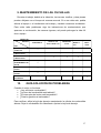
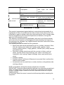
MOTOCULTIVADOR/TILLER
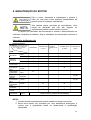
Dimensions / Dimensão / Dimensión
(mm) 1480×650×980
Net weight / Peso Líquido / Peso neto
(Kg) 100
Gross weight / Peso Bruto / Peso
bruto (kg) 115
Transmission system / Sistema de
Transmissão / Sistema de
transmisión
Gear / Engrenagem / engranaje
Cutting Width / Largura de corte /
Longitude del corte (mm) 240-650 mm
Tilling depth / Profundidade /
Profundidad (mm) 100-240
Speed control / Marcha / Marcha Forward, Neutral, Reverse / Ré, Neutro, Frente
/ reversa, neutro, frente
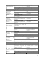
ENGINE / MOTOR / MOTOR
Model/modelo / Modelo TE70O
Type /Tipo / Tipo Single cylinder / Monocilíndrico, 4T, OHV 25,
air cooled / refrigerado a ar
Displacement / Cilindradas /
Cilindrada (cc)
212
Power max /Pot. Máxima /
Pot.máxima (HP/rpm)
(7.0) / 3600
Torque Máx / Torque máx. (n.m/rpm) 12 / 2,500
Starting system/ Sistema de
partida/Sistema de arranque
Recoil start / Partida retrátil / Arranque retráctil
Filtro de ar/Filtro de aire Oil Bath filter / Banhado a Óleo / Bañado en
aceite
Gasoline Tank capacity / Capacidade
tanque combustível / Capacidad
tanque de combustible (L)
3.6
Combustible consuption / Consumo
combustível/ Consumo combustible
(g/kW.h)
395
Engine oil capacity / Capacidade óleo
motor / Capacidad aceite en el motor
(L)
0.6

4
PREFACE
Thank you for purchasing TOYAMA Tilling.
This manual covers the operation and maintenance of a Tilling. The information and
specifications included in this publication were in effect at the time of approval for
printing. No part of this publication may be reproduced without written permission.
This manual should be considered a permanent part of the Tilling and should remain
with the Tilling if it is resold. The illustration may vary according to the type.
Keep this owner’s manual handy, so you can refer to it at any time. This owner’s
manual is considered a permanent part of the Tilling and should remain with the Tilling
if resold.
If a problem should arise, or if you have any questions about the Tilling, consult you
authorized dealer.
PREFACIO
Obrigado por comprar um Motocultivador TOYAMA.
Este manual contém informações para operação e manutenção do Motocultivador. As
informações e especificações incluídas nesta publicação estavam em vigor no momento
da aprovação para impressão. Nenhuma parte desta publicação pode ser reproduzida
sem permissão por escrito. A ilustração pode variar de acordo com cada modelo de
equipamento.
Mantenha este manual do proprietário perto, para que possa consultá-lo a qualquer
momento. Este manual é considerado uma parte permanente do Motocultivador e deve
permanecer com o Motocultivador se revendido.
Se surgir um problema, ou se você tem dúvidas sobre o Motocultivador, consulte o seu
revendedor autorizado TOYAMA.
PROLOGO
Gracias por comprar este Motocultivador TOYAMA.
Este manual cubre la operación y el mantenimiento del Motocultivador.La información
y las especificaciones incluidas en esta publicación son efectivas para la fecha de
aprobación de impresión.
Ninguna parte de esta publicación puede ser reproducida sin autorización.Este manual
debe ser considerado parte permanente del Motocultivador y debe mantenerse con el
producto en caso de ser revendido.Algunos detalles podrán cambiar dependiendo del
modelo.
Conserve este manual a la mano para que usted se pueda referir a él em cualquier
momento.
En caso de presentarse algún problema, o si usted tienen alguna pregunta sobre el
Motocultivador, contacte a su distribuidor TOYAMA.

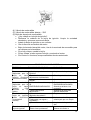
5
INDICE
1. INTRODUCTION ........................................................................................................ 6
2. SECURITY INSTRUCTIONS ..................................................................................... 6
3. GENERAL CHART ..................................................................................................... 8
4. ASSEMBLY ................................................................................................................. 9
5. OPERATION ............................................................................................................. 12
6. ROTARY TILLER STATE ADJUSTMENT ............................................................ 14
7. ENGINE OPERATION .............................................................................................. 16
8. MAINTENANCE OF GASOLINE ENGINE ............................................................ 19
9. MAINTENANCE METHOD OF ROTARY TILLER .............................................. 21
10. COMMON FAULTS AND REMOVING WAYS ................................................... 22
1. INTRODUÇÃO .......................................................................................................... 24
2. INSTRUÇÕES DE SEGURANÇA ............................................................................ 24
3. COMPONENTES ....................................................................................................... 26
4. MONTAGEM ............................................................................................................. 28
5. OPERAÇÃO ............................................................................................................... 30
6. AJUSTES ................................................................................................................... 31
7. OPERAÇÃO DO MOTOR ........................................................................................ 33
8. MANUTENÇÃO DO MOTOR ................................................................................. 36
9. MANUTENÇÃO DAS FACAS ................................................................................. 38
10. GUIA SOLUÇÃO DE PROBLEMAS ..................................................................... 39
1. INTRODUCCIÓN .................................................................................................. 42
2. INSTRUCCIÓN DE SEGURIDAD........................................................................ 42
3. COMPONENTES ....................................................................................................... 44
4. MONTAJE ................................................................................................................. 45
5. OPERACIÓN .......................................................................................................... 47
6. AJUSTES ................................................................................................................ 49
7. OPERACIÓN DEL MOTOR .................................................................................. 50
8. MANTENIMIENTO DEL MOTOR ....................................................................... 54
9. MANTENIMIENTO DE LAS CUCHILLAS......................................................... 57
10. GUÍA SOLUCIÓN DE PROBLEMAS ............................................................... 57

6
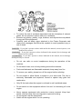
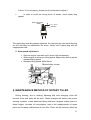
1. INTRODUCTION
The preparation of land for agricultural, forestry or leisure activities implies
the use of different equipment, which is chosen according to the type of existing
material.
The Motorcultivator is a powerful single-axle combustion engine tool for
agricultural work, which can be driven by a driver on foot or even on a semi-
trailer.
This equipment is indicated for the cultivation of the earth in small properties
and its main function is to elevate and to reverse the ground to improve the
aeration and the infiltration of water. Among the highlighted function can also be
used in cleaning chicken bed, carriage, spray and small irrigations.
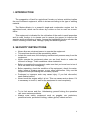
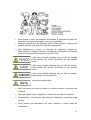
2. SECURITY INSTRUCTIONS
Never allow an untrained person to operate the equipment.
This machine should only be operated by adults.
Isolate the work area, thus keeping unauthorized persons away from the
equipment.
Never operate the equipment when you are tired, drunk or under the
influence of drugs. These conditions cause inattention.
Before connecting the equipment, make sure that you know how to turn it
off in the event of an emergency.
Before operating, check the condition of the equipment, check for cracks,
leaks, loose or missing screws, or any other malfunction. Only use the
equipment after performing the necessary repairs.
Prolonged or improper work may cause injury. If you feel discomfort,
seek medical advice.
Never touch the engine while it is hot. This can cause serious burns. If it
is necessary to touch it, wait for the equipment to cool completely.
Try to feel secure and firm. Unbalancing yourself during the operation
can cause serious accidents.
Always wear safety equipment such as goggles, ear protectors,
protective boots, protective clothing, rubber gloves, helmet and etc..

To reduce the risk of accidents associated with the inhalation of exhaust
gases, do not operate in places with poor ventilation.
Remove any jewelry, jewelry, rings, watches, and objects that may attach
to any part of the equipment.
Carefully read all safety signs attached to the Power Generator and
observe all messages that follow the symbols to avoid possible injury or
risk of death.
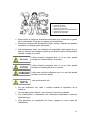
DANGER:If you don’t operate as those indicated in the manual, serious injuries, even
death will be caused.
WARNING:If you don’t operate as those indicated in the manual, device damage and
injures will be caused.
ATTENTION:If you don’t operate as those indicated in the manual, device damage
and injures may be caused.
Do not use radio or music headphones during the operation of the
machine.
Do not wear loose, torn or bulky clothing around the machine.
Fuels and lubricants are flammable materials, keep away from fire.
To ensure your safety, please turn off the engine before refueling.
Do not smoke or allow flames or sparks in your work area. The fuel is
extremely flammable and explosive, flames or sparks may ignite fuel
combustion.
Only fill the tank when the engine is cold and in well ventilated areas.
Do not switch on the equipment without fuel and / or lubricating oil in the
engine.
Never operate equipment with protective covers removed. Keep feet,
hands, and hair away from moving parts to prevent bruising.
Do not smoke near the equipment.
Switch off the engine when it is not operating.

8
Do not change or disable any safety device.
Never leave appliance unattended.
Keep the control elements of the appliance always dry, clean, free of oil
and grease. Control elements such as, for example, on / off switches,
accelerators, etc., must not be improperly locked, manipulated or altered.
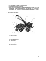
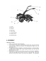
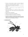
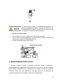
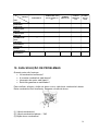
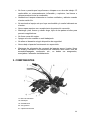
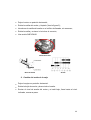
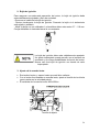
3. GENERAL CHART
1. Hand control assy
2. Trailer
3. Mud fender
4. Rotary tilling equipment
5. Tilling box assy
6. Gear box assy
7. Gasoline engine
8. Belt transmission

9
9. Bumper
10. Belt cover
11. Front tire
12. Rear wheel
13. Clutch handle
14. Throttle handlebar
15. Steering column
16. Shut down switch
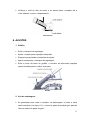
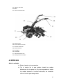
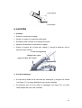
4. ASSEMBLY
Unpacking assembly
Take out rotary tiller and accessories.
Fix the body of rotary tiller, install walking wheels, then use pin 8×40 and
clip to fix them. Install rear wheels in the appropriate height, then use
lock bolt to fix it.
Tilling/ditching blades installation: install tilling blades or ditching blades
on both sides of output shaft, edge towards forward, and then use pin
M8×40 and clip to fix it.
Mud fender (or narrow mud fender) and side mud fender installation:
Install left and right mud fenders on the tiller, fixing with bolt M6×12 (8
pcs) and locknut M6 (8 pcs), and screw up by spanner. The adjustable

10
part of mud fender place is as the picture. Then install side mud fender
on both sides and screw up small handles.
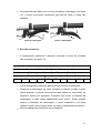
Handle bar installation: assemble handle bar components on tiller. The
handle bar frame position is symmetrical accordingly for the tiller, then
use the locked pin to fix the frame.
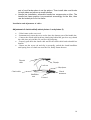
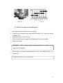
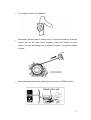
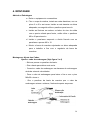
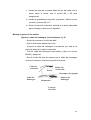
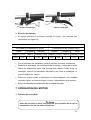
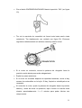
Installation and adjustment of cables
Adjustment of clutch cable(Look at picture 1 and picture 2)
- Unlock nuts on the screw rod.
- Instantaneously rotate the screw rod to show the shortest part of the handle bar.
- Connect the clutch cable head into clutch plug behind the gear box assy, thread
the cable into axis pin M6×20, and fix with jump ring.
- Properly pull down the clutch cable and fix the clutch cable head to handle bar
bottom.
- Rotate out the screw rod and clip it repeatedly, unlock the clutch handlebar
until spring force of clutch can reset the bar, finally fasten the nuts.
Picture 1
Throttle
cable
Throttle
switch
Lock nut
Shut down
switch
Clutch
handlebar
Handlebar
lock
Clutch cable

11
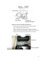
Picture 2
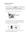
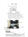
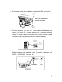
Adjustment of oil throttle cable. (Look at picture 3)
Screw oil throttle switch to the minimum scale.
Thread the steel wire-rope into the oil throttle, the pole and plug of
regulation panel of gasoline engine.
Fasten the steel wire-rope and fix the screw.
Adjust the oil throttle switch repeatedly until the throttle bar of the
regulation panel can be in the fastest or slowest position.

12
Picture 3
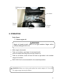
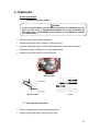
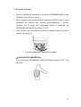
5. OPERATION
Daily Check
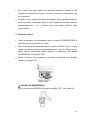
1. Check engine oil:
Make engine horizontal;
Take out oil sticker, and clean it (Look at picture4);
Insert oil sticker into filling hole, but don’t screw on;
Take out oil sticker, check oil level. Oil level is right when in the marked
range of oil sticker;
SAE 10W-30 oil is recommended for the usual temperature.
WARNING Please use clean, good quality four stroke engine oil. If use dirty
oil, engine usage time may be shorter.
WARNING
Engine oil should be 0.6L when it is in right condition. Engine will be
seriously damaged if oil is low
Binding post, lock
nut
Permanent
seat
Throttle
co
ntrol
Throttle
Cable
Air cleaner

13
Picture 4 Table 4
2. Check oil in gear box and tilling box
Set rotary tiller horizontal, screw out oil bolt
Usually the oil amount: gear box should be about 0.5L, tiller box should
be about 1.2L;
Recommended oil is No. 20 oil
Place the shift lever of gear box and tilling box in neutral position
Check air cleaner
WARNING: Don’t make engine working without air cleaner, if so,
engine will be abraded
Add oil into air cleaner: disassemble the cover, then add about 0.1L oil
number 20
WARNING: Oil level can’t over the mark

14
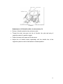
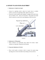
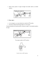
6. ROTARY TILLER STATE ADJUSTMENT
1. Adjustment of handle bar height:
Loosen the regulating handle, adjust the handle frame to suitable
position, screw into the regulating handle, tighten the wing nut.
Loosen the locked handlebar and standpipe, standpipe and handle frame
can be rotated in 330 °, which has 18 positions. Then tighten the locked
handle, operate the rotary tiller through adapting to different position.
Picture 5
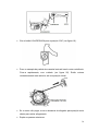
2. Adjustment of tilling depth
Adjust resistance rod downwards, tilling depth will increase. Adjust
resistance rod upwards, tilling depth will decrease.
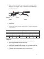
3. Usage and adjustment of clutch:
When clutch handle is clenched, clutch is opened, the engine stops
inputting power to tiller, tiller blades stop rotating (Look at picture 6).

15
When we clench the handle lock, clutch handle is opened, clutch is
connected. In the condition, power is transmitted to tiller, blades begin to
work. (Look at picture 7).
Picture 6 Picture 7
4. Gear Choice:
Gear box has 5 gears, including neutral position. The gears are optional
(Look at Table 5)
Gear box Tilling box(Using with chain box together)
Transmission speed(km/h) Blades rotary speed (rpm)
Forward Stop Back Fast Stop Slow
slow Fast Neutral
fast slow fast slow Neutral
fast slow
4.83 2.55 X 3.45 1.82 553 299 X 311 168
Table 5
Change gear
Counterclockwise turn the throttle switch to the right position (mini).
Clench clutch handlebar, and make clutch open.
Change shift lever to the gear you need.
Loosen clutch handlebar, make machine into the changed gear, then
open the throttle to increase the speed into the work.
If necessary, we may start engine to check if clutch can work.
Handlebar
lock
Clutch
handlebar

16
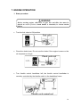
7. ENGINE OPERATION
1. Start procedure
Turn the fuel valve to ON position.
Close the choke lever. Do not use the choke if the engine is warm or the
air temperature is high.
Turn throttle control handlebar left, the throttle control handlebar is
remotely controlled by the throttle switch in the handlebar frame.
WARNING
Before starting engine, shift lever of gear box and tiller box must be
placed on neutral position, clutch handle is clenched (i.e. loosen tension
pulley
)

17
Turn engine switch to ON position.
Repeatedly pull the rope of starter until you feel the resistance, and then
quickly pull out the rope. Don’t suddenly loosen the handle of recoil
starter, or it may be sprang back to strike the engine. You should release
it slowly
After preheating the engine, gradually move choke to OPEN position.

18
Adjust rotary speed of engine through the throttle switch (or throttle
handle)
2. Stop engine
In an emergency, you may directly turn switch to OFF position.
Generally, adopt the following steps to turn off engine.
Counterclockwise turn throttle switch to minimum scale or turn throttle handle to
the right
Turn engine switch to OFF position.
Put fuel valve to OFF position

19
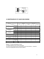
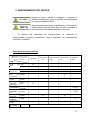
8. MAINTENANCE OF GASOLINE ENGINE
Remark: “0” shows maintenance content.
(1) Please maintain more in dust environment.
(2) Some of the projects may be maintained by authorized dealers,unless the
user has the appropriate tools and repair capacity.
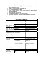
M a i n t e n a n c e
P e r i o d
I t e m
Every
day
The first
month or 20
hours
Third months or
50hours
Every half
year or 100
hours
Every year or
300 hours
Engine lubricant
Check
amount 0
Replace 0 0
Reduction gear
lubricant(applicable to
some type)
Check
amount 0
Replace
0 0
Air cleaner
Check
0
Clean 0(1)
Dust cover Clean
0
Spark plug Check and
clean 0
Spark eliminator
(optional) Clean 0
Tank and filter Clean
0(2) 0(2)
Valve Check and
readjust
Fuel circuit Check Every two years (2) (Change it if possible)

20
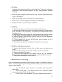
1. Air filtre:
A dirty air filter blocks the airflow to the carburetor. To prevent carburetor
malfunction, clean the filter regularly. On dry, dusty grounds, redouble
cleaning.
Never operate equipment without an air filter, serious malfunctions may
occur in the engine.
Open the air filter cover and remove the air filter element.
Clean the air filter thoroughly with hot water and detergent.
Replace the filter cover and secure it with the.
2. Oil Filter
1. Remove the wing nut, and remove the cap and air filter cap.
2. Remove the air filter from the lid, rinse the lid and filter in soapy water,
rinse, and allow to dry completely. Or clean with non-flammable solvent
and allow to dry.
3. Dip the filter into clean engine oil, and squeeze to remove any excess
oil. The engine will release smoke if too much oil is left in the foam.
4. Remove used oil from the tank, remove any dirt with non-flammable
solvent and dry the tank.
5. Fill the reservoir to the OIL LEVEL mark with the same oil as is
recommended for the engine.
6. Reassemble the air filter, and tighten the butterfly nut securely.
3. Air Filter with double element
1. Remove the butterfly nut from the air filter cover and remove the
cover.
2. Remove the butterfly nut from the air filter, and remove the filter
3. Remove the paper filter foam.
4. Check the filter elements, and replace them if they are damaged.
Always replace the paper element in the time indicated by this manual.
5. Clean filter elements that can be reused.
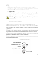
4. Maintenance of spark plug
Don’t use the spark plug without correct caloricity scale. The machine version is
F7TC. To keep engine in good working condition, spark plug must be clean and
without carbon deposit.
Use the specific sleeve spanner to assemble and disassemble
spark plug.
Check spark plug, if it is distinctly worn out or dehisced, please
change a new one. If it is still well, clean it.
Check spark plug clearance, the right clearance should be 0.7-
A página está carregando ...
A página está carregando ...
A página está carregando ...
A página está carregando ...
A página está carregando ...
A página está carregando ...
A página está carregando ...
A página está carregando ...
A página está carregando ...
A página está carregando ...
A página está carregando ...
A página está carregando ...
A página está carregando ...
A página está carregando ...
A página está carregando ...
A página está carregando ...
A página está carregando ...
A página está carregando ...
A página está carregando ...
A página está carregando ...
A página está carregando ...
A página está carregando ...
A página está carregando ...
A página está carregando ...
A página está carregando ...
A página está carregando ...
A página está carregando ...
A página está carregando ...
A página está carregando ...
A página está carregando ...
A página está carregando ...
A página está carregando ...
A página está carregando ...
A página está carregando ...
A página está carregando ...
A página está carregando ...
A página está carregando ...
A página está carregando ...
A página está carregando ...
A página está carregando ...
A página está carregando ...
A página está carregando ...
A página está carregando ...
A página está carregando ...
-
 1
1
-
 2
2
-
 3
3
-
 4
4
-
 5
5
-
 6
6
-
 7
7
-
 8
8
-
 9
9
-
 10
10
-
 11
11
-
 12
12
-
 13
13
-
 14
14
-
 15
15
-
 16
16
-
 17
17
-
 18
18
-
 19
19
-
 20
20
-
 21
21
-
 22
22
-
 23
23
-
 24
24
-
 25
25
-
 26
26
-
 27
27
-
 28
28
-
 29
29
-
 30
30
-
 31
31
-
 32
32
-
 33
33
-
 34
34
-
 35
35
-
 36
36
-
 37
37
-
 38
38
-
 39
39
-
 40
40
-
 41
41
-
 42
42
-
 43
43
-
 44
44
-
 45
45
-
 46
46
-
 47
47
-
 48
48
-
 49
49
-
 50
50
-
 51
51
-
 52
52
-
 53
53
-
 54
54
-
 55
55
-
 56
56
-
 57
57
-
 58
58
-
 59
59
-
 60
60
-
 61
61
-
 62
62
-
 63
63
-
 64
64


em outros idiomas
- español: TOYAMA TT65A El manual del propietario
- English: TOYAMA TT65A Owner's manual


