BERG fuego cx series Manual do usuário
- Categoria
- Acessórios para bicicletas
- Tipo
- Manual do usuário
Este manual também é adequado para


INDEX
5
6
6
6
6
7
7
7
8
8
9
9
11
12
13
13
14
14
14
14
16
16
16
16
16
18
18
18
19
20
20
21
USER’s MANUAL
WARNING / IMPORTANT
Please note this symbol throughout the manual and pay special attention to statements preceded.
RANGE OF MODELS AND STANDARDS
TYPES OF BICYCLES AND RECOMMENDATIONS FOR USE
BEFORE USING THE BIKE
GENERAL WARNING
USING A BABY CHAIR/CARRYING LUGGAGE/HARNESS
USING ACCESSORIES NOT ORIGINALLY MOUNTED ON THE BICYCLE
GENERAL DIRECTIONS FOR USE
COMPOSITE MATERIALS – USE AND NECESSARY CAUTION
SAFETY AND MAINTENANCE PLAN
SAFETY AND PROTECTION
SADDLE HEIGHT AND HANDLEBAR ADJUSTMENT
CHECK AND ADJUST BRAKES
USING CLIPLESS PEDALS
CHECK AND ADJUST TYRE PRESSURE
CHECK AND ADJUST THE QUICK RELEASE LEVER
SUSPENSION ADJUSTMENT
MAINTENANCE ADVICE
CLEANING AND LUBRICATION
TRANSMISSION MAINTENANCE AND ADJUSTMENT
DERAILLEUR
BRAKE MAINTENANCE
BMX
RECOMMENDATIONS FOR SAFE USE
ROTOR ADJUSTMENT
PEG ASSEMBLY INSTRUCTIONS
CHILDREN
SPECIAL NOTE FOR PARENTS
ASSEMBLING AND MOUNTING TRAINING WHEELS
SIZE GUIDE
TORQUE SPECIFICATIONS TABLE
CERTIFIED WARRANTY REGISTER
LIFETIME WARRANTY

5
ENGLISH
RANGE OF MODELS AND STANDARDS
This manual encompasses all bicycle ranges and models produced by Berg Cycles. Berg Cycles models meet the requirements
established in the European Directive, CEN (European Committee for Standardization) and ISO (International Organisation for
Standardisation).
The following table includes descriptions of bicycle model ranges belonging to BERG CYCLES and the corresponding standards
associated to each one:
Note: The figures for the maximum load allowed correspond to the type of bicycle and cyclist’s weight along with any loads being
carried on the bicycle.
To measure the maximum saddle height, place it at the minimum insertion level (1) and measure the height from the floor to the
top of the saddle (2) as shown in the following image.
Key:
H maximum saddle height
1 minimum insertion level
2 floor
MODEL CLASSIFICATION
MOUNTAIN BICYCLES
ROAD BICYCLES
CITY/TREKKING BICYCLES
CITY/TREKKING BICYCLES
BMX CATEGORY 1
BMX CATEGORY 2
JUNIOR BICYCLE
CHILDREN’S BICYCLE
TRAINING BICYCLE
NAME OF GROUP
VERTEX SERIES
TRAILROCK SERIES
SIERRA MTB SERIES
TRAIL SERIES
STUKA SERIES
FUEGO SERIES
FUEGO CX SERIES
CROSSTOWN TREKKING SERIES
CROSSTOWN CLASSIC SERIES
SIERRA CITY SERIES
URBAN SERIES
PARK SERIES
SPORTY SERIES
SPORTCROSS SERIES
EASY FOLDING SERIES
TRIBE 360 SERIES
TRIBE PRO SERIES
BLAST/CHARM 24” SERIES
BLAST/CHARM 20” SERIES
BLAST/CHARM 16” SERIES
BLAST/CHARM 14” SERIES
BLAST/CHARM 12” SERIES
BLAST/CHARM
BALANCE BIKE SERIES
STANDARD MET
ISO 4210 - 2
ISO 4210 - 2
ISO 4210 - 2
ISO 4210 - 2
ISO 4210 - 2
ISO 4210 - 2
ISO 4210 - 2
ISO 4210 - 2
ISO 4210 - 2
ISO 4210 - 2
ISO 4210 - 2
ISO 4210 - 2
ISO 4210 - 2
ISO 4210 - 2
ISO 4210 - 2
EN 16054
EN 16054
ISO 4210 - 2
ISO 4210 - 2
ISO 8098
ISO 8098
ISO 8098
EN 71
MAXIMUM ALLOWED
WEIGHT (CYCLIST + ACCES-
SORIES +LUGGAGE)
100 Kg
100 Kg
100 Kg
100 Kg
100 Kg
100 Kg
100 Kg
100 Kg
100 Kg
100 Kg
100 Kg
100 Kg
100 Kg
100 Kg
80 Kg
45 Kg
80 Kg
40 Kg
40 Kg
30 Kg
25 Kg
25 Kg
25 KG
MAXIMUM SADDLE
HEIGHT
635mm OR ABOVE
635mm OR ABOVE
635mm OR ABOVE
635mm or above
435mm or above
435mm or above
635mm OR ABOVE
AND LESS THAN 750mm
BETWEEN 435mm AND 635mm
LESS THAN 435mm
H
2
1

6 7
ENGLISH
ENGLISH
TYPES OF BICYCLES AND RECOMMENDATIONS FOR USE
BEFORE USING THE BIKE
Berg Cycles oers dierent types of bicycles, designed for specific use, as shown in the following table. Using these bicycles in
situations contradictory to these recommendations may result in accidents and harm to oneself and property.
GENERAL WARNING
Cycling can be a hazardous activity even under the best of circumstances. Proper maintenance of your bicycle is your responsibility
as it helps reduce the risk of injury. This manual contains many “Warnings” and “Cautions” concerning the consequences of failure
to maintain or inspect your bicycle. Many of the warnings and cautions refer to the risk of falls or accidents. As any fall can result in
serious injuries, including death, we do not repeat the warning of possible injury or death whenever the risk of falling is mentioned.
USING A BABY CHAIR/CARRYING LUGGAGE/HARNESS:
Carriers, child safety seats and trailers may be used on city and trekking bicycles (compatibility will depend on the chosen transport
accessory).
Mountain bicycles may also be compatible with these transport accessories, although it will depend on each accessory.
Do not use any transport accessory (carriers, child safety seats and trailers) on bicycles built out of composite materials.
Always contact retailer to check your bicycles compatibility with the various transport accessories available on the market.
Using any transport accessory such as carriers, child safety seats and trailers can aect your bicycle’s stability and ride.
You should check with your retailer how to mount these accessories; accessories mounted incorrectly could result in risk of personal
injury or property damage.
Before using your bicycle equipped with a transport accessory, check that it is functioning properly. Check the tightness of fasten-
ing bolts and ensure there are no gaps.
The weight limit indicated by manufacturers of these accessories should not be exceeded under any circumstances.
Note: City or trekking bicycles should cover all spring mechanisms (if applicable) when using a child safety seat to avoid physical injury
to the child.
USING ACCESSORIES NOT ORIGINALLY MOUNTED ON THE BICYCLE
USING AERODYNAMIC EXTENSIONS ON ROAD BICYCLES
Using aerodynamic extensions on road bicycles could aect the steering by interfering with drive and braking behaviour.
You should test your mounted bicycle with aerodynamic extensions in a quiet area to familiarise yourself to steering. Always brake
in good time and avoid sudden movements when cycling.
MOUNTING ACCESSORIES NOT PROVIDED WITH THE BICYCLE
If you suspect your bicycle has been provided with a dismounted accessory, please contact your retailer. Visibility accessories
(lights, reflectors and bell) might not be mounted to your bicycle when delivered. Please contact your retailer to ensure these
accessories are correctly mounted. You should also request from your retailer replacement pieces (e.g. batteries or bulbs) in case
you may need them.
When mounting the pedals, please pay attention to the inscription indicating the correct mounting side (located on the pedals
thread). Inscription “L” refers to the left pedal, while inscription “R” refers to the right pedal.
Note: Correct mounting of pedals is essential to ensure your safety. Please ask your retailer to mount the pedals. Always check the
pedals are screwed on tightly before each use.
GENERAL DIRECTIONS FOR USE
When riding a bicycle, comply with the same rules of transport for other vehicles, including giving way to pedestrians and stopping
at red lights and stop signs.
For more information, contact your country’s road transit authority.
Ride your bicycle in a foreseeable manner and in a straight line. Never ride your bicycle on the wrong side of the road. Use correct
hand signals to indicate changes of directions or stops.
Ride cautiously whilst making yourself visible to others on the road as they may have diculty seeing you.
Concentrate on the route ahead of you. Avoid potholes, gravel, wet areas along the route, oil slicks, edges of pavements, road
humps, sewer grates and other obstacles.
Pass railway tracks at a 90-degree angle or on foot and carry your bicycle on your arm.
Be prepared for the unexpected; car doors opening suddenly or cars reversing out of access paths not in your line of sight.
Be extra careful at intersections and when preparing to overtake other vehicles.
Familiarise yourself with all of the bicycle’s features. Practise changing gears, braking and use of clipless pedals, if mounted.
If you wear long trousers, use hooks or elastic buckles around your legs to avoid them getting caught on the chain.
Wear appropriate clothing for cycling and avoid shoes that expose your toes.
Your bicycle has several mechanical components that might get caught on your clothing while riding (or during any type of use,
including maintenance work). Pay special attention when using your bicycle to prevent your clothes from getting caught on any of
these mechanical components.
Do not carry loads or passengers that will aect your visibility or control of the bicycle. Do not use objects that may restrict your
hearing.
Do not block the brakes. When braking, always use the rear brake first and then the front brake. The front brake is stronger and if
not used correctly may cause you to lose control and fall.
Keep a safe distance from other riders, vehicles and objects when braking. Distances and forces related to safe braking depend on
weather conditions.
COMPOSITE MATERIALS – USE AND NECESSARY CAUTION
Composite materials are increasingly used in the manufacturing of bicycles, as they possess very interesting mechanical properties.
However, these materials have some flaws and should be subject to frequent periodic inspections. Composite materials are sensi-
tive to high temperatures and may undergo structural changes if they are exposed to these high temperatures for extended periods
of time (e.g. temperatures resulting from sudden sharp braking on a composite wheel).
You should check the manufactured composite components regularly and look for signs of cracks or surface changes (scratches,
blisters and discolouration).
In regards to wheels made of composite materials, you should pay attention to any damage caused by impact and high temper-
atures.
Damaged wheels may be invisible when performing a visual check. You should always make the most of breaks to check and im-
mediately contact your retailer if you notice any change to the normal functioning of the wheels.
Note: Never attempt to repair a component made of composite material. This may lead to the component’s malfunction and result in
physical injury and property damage.
If your bicycle has been supplied with tubular tyres, please contact your retailer for proper mounting.
Consult your retailer if you have questions on the use/maintenance of composite materials.
These bicycles have been designed for o the road use on trails and on the road and bicycle paths.
They are equipped with a strengthened frame and other components, like wider tyres, with a
unique trail pattern and a wide gear range.
Maximum saddle height should be higher than 635mm.
These bicycles have been designed for amateur use on high-speed roads, fitted with a handlebar
that adapts to various positions (for an aerodynamic posture), with a wide gear range, maximum
tyre length of 28mm and maximum weight of 12kg (when fully mounted).
Maximum saddle height should be higher than 635mm.
These bicycles are not built for trails and paths o the road.
These bicycles have mainly been designed for leisure and commuting on the road. Maximum sad-
dle height should be higher than 635mm. These bicycles are not built for trails and paths o the
road.
These bicycles have been designed for road use and bicycle paths.
They are also suitable for acrobatics (on the ground and in the air).
They are divided into two categories:
Category 1 – For cyclists weighing less than 45 kg.
Category 2 – For cyclists weighing more than 45 kg.
Maximum saddle height should be higher than 435mm.
These bicycles have been designed for road use by young adults weighing less than 40kg and a
saddle height between 635mm and 750mm.
These bicycles are not built for trails and paths o the road.
These bicycles have been designed for on the road and bicycle paths.
These bicycles are not built for trails and paths o the road.
Saddle height should be between 435mm and 635mm.
They are considered to be toys. They should not be used on roads or trails. They should always be
used under parental supervision. Maximum saddle height should be less than 435mm.
MOUNTAIN BICYCLES
ROAD BICYCLES
CITY/TREKKING BICYCLES
BMX BICYCLES
JUNIOR ADULT BICYCLES
JUNIOR CHILDREN BICYCLES
TRAINING BICYCLES

8 9
ENGLISH
ENGLISH
SAFETY AND MAINTENANCE PLAN
Your local retailer provides the first comprehensive check on the bicycle. This check should be carried out after the first five hours
of use and up to a limit of two months after the purchase date.
The check may not be carried out immediately; it will depend on the retailer’s workflow.
The safety and maintenance plan checks should be carried out according to the following schedule:
SCHEDULE 1:
SCHEDULE 2
SCHEDULE 3
Note: Whenever a fault is found, you should ensure it is repaired. All bicycles should be subject to periodic checks. Good bicycle mainte-
nance will help retain its original use and safety qualities. Do not forget to store your bicycle in a dry, sheltered area away from saline en-
vironments. Do not forget to frequently clean the spokes and bolt heads on your bicycle. Manufacturers usually use steel in their man-
ufacturing to ensure adequately strong components. Exposing steel to saline and humid environments can enhance surface oxidation.
SAFETY AND PROTECTION
Cyclists are recommended to wear appropriately sized safety helmets, approved by the EN1078 (adult and child) when riding a
bicycle. In addition, if carrying a passenger in the child safety seat, then they must also wear a helmet.
A proper helmet should fit comfortably, be light (have good ventilation) and be appropriately sized (covering the forehead).
Many countries require specific safety features. It is your responsibility to familiarise yourself with the laws of the country where
you cycle and to comply with all applicable laws, including properly equipping yourself and your bicycle in accordance with legal
requirements. Reflectors are important safety features, designed to be an integral part of the bicycle. Reflectors are designed to
capture and reflect street and car lights in order to help you be seen and recognised as a moving cyclist. Inspect the reflector and
FREQUENCY
BEFORE EVERY
USE
FREQUENCY
WEEKLY
MONTHLY
EVERY 6 MONTHS
ANNUALLY
COMPONENT
BRAKE
TYRES/INNER TUBE
WHEELS
STEERING
CHAINSET AND
PEDALS
GEARS
FRAME AND FORK
COMPONENT
CHAIN/DERAILLEUR
BRAKE LEVERS
GEAR LEVERS
BRAKE AND GEARS CABLES
HUBS AND SPROCKETS
CHAIN SET/PEDALS
WHEEL BEARINGS
HEADSET
SEAT POST
CHECK
BRAKES AND
DAMAGED CABLES
PRESSURE
RIM AND SPOKES
WHEEL TIGHTENING
HANDLEBAR AND HEADSET
CHAINSET AND
PEDAL TIGHTENING
GEARS AND
DAMAGED CABLES
CRACKS OR KINKS
LUBRICANT
Lubricant or Light oil for chain
Lithium-based grease
Lubricant or Light oil for chain
Lithium-based grease
PROCEDURE
Ensure the front and back brakes work perfectly.
Ensure brake cables are lubricated and do not immediately appear worn.
Ensure tyres are inflated to recommended pressure as indicated on the side
of the tyre and do not appear excessively worn.
Double check wheel rims turn properly and show no obvious signs of torsion.
Ensure they have the correct amount tension and are in the closed position.
Double check they are properly fixed and tightened.
Ensure pedals are securely fixed to chainset.
Double check the cranksets are secured to the crankset adapter.
Check front and back gears function properly.
Check frame and fork are not kinked or broken.
PROCEDURE
Clean and then dab or
sprinkle 3 drops of oil
Dismount and Lubricate
Lubricate
Dismount and Lubricate
FREQUENCY
AFTER EVERY USE
AFTER 25 HOURS
AFTER 25 HOURS
AFTER 50 HOURS
AFTER 100 HOURS
AFTER 100 HOURS
AREA
Brace/oil seals
Bolt tightening
Oil seals
Suspension function
Travel adjust
Suspension function
PROCEDURE
Clean/Lubricate
Tighten
Lubricate w/ Teflon oil
General clean and lubrication by retailer
Change oil and lubrication w/
Teflon oil by retailer
Full inspection and replacement (seals/oil)
by retailer
COMPONENT
SUSPENSION
FRONT SHOCK
their mounting brackets regularly to ensure they are clean, straight, in perfect condition and securely mounted. Ask your retailer to
replace damaged reflectors and straighten or tighten the ones that are bent or loose.
USE IN HUMID WEATHER
Pay extra attention when cycling in the rain.
You should pay extra attention when cycling in the rain.
Brake in good time as you will need a greater distance to stop.
Lower your speed, avoid sudden braking and be more cautious around bends.
Opt for a more visible position on the road.
Use reflective clothing and safety lights.
Potholes and slippery surfaces such as oil slicks and railway tracks can become even more dangerous when wet.
CYCLING AT NIGHT
Pay extra attention when cycling at night.
Double check the bicycle is equipped with a full set of clean reflectors and placed correctly.
Use a combination of properly functioning lighting features, comprising of a front white light and a rear red light. If you use battery
lights, make sure the batteries are charged. Some available taillights have a flashing mechanism that increases visibility. Use
reflective and light-coloured clothing. Lower your speed and use familiar routes with street lighting if possible.
SADDLE HEIGHT AND HANDLEBAR ADJUSTMENT
Measure and adjust saddle height according to user’s height.
(See size guide on page 19)
After adjusting saddle height, check if the “minimum permitted height”, located on
the seat post, is not above the seat tube.
The use of the seat post above the minimum allowed height is dangerous and can
result in physical injury and property damage.
ADJUST THE HANDLEBAR STEM:
Adjusting the height of the handlebar stem (when possible) by inserting the headset
and ensuring the minimum insertion height mark is not visible.
Using the headset above the minimum insertion height is dangerous and can result in
physical injury and property damage.
Note: The headset does not adjust the height of the stem.
Note: Failure to properly tighten the stem’s mounting bolt, the handlebar-clamping bolt
and the grips’ fastening bolts can impair cycling, leading to loss of control and falling.
Place the bicycle’s front wheel between your legs and attempt to twist the handlebar/
stem using only reasonable force to do so.
If you can twist the stem towards the front wheels, turn the handlebar towards the stem,
or turn the grips towards the handlebar, then you must tighten the respective bolts prop-
erly.
CHECK AND ADJUST BRAKES
Check what kind of brakes your bicycle is equipped with and refer to the appropriate mounting instructions.
On all bicycles, brakes are activated by levers mounted on the handlebars except for the brake freehub, as explained in this guide.
The following image explains how the brand’s bicycle’s front and rear brakes operate.
Before each use, check the brakes.
Brakes are a key safety mechanism for the cyclists, and should be checked and adjusted regularly and before each use.
REAR BRAKE
MAXIMUM HEIGHT MINIMUM INSERTION MARK
(SHOULD NOT BE VISIBLE)
STEM TIGHTENING SCREW
MAXIMUM
HEIGHT/ MINIMUM
INSERTION MARK
HANDLEBAR
FIXING BOLT
2 ½ (64mm)
SURPLUS
FRONT BRAKE

10 11
ENGLISH
ENGLISH
ADJUST V-BRAKE BRAKES
1. Check pads are aligned with rim surface;
2. Brake pads must be adjusted so as to be between 1 and 2 mm away from the fitted rim;
3. The brake pads should be centred on the rim and inclined forward so that the back of each brake pad is approximately 0.5 to
1.0mm away from the rim than the front pad part;
4. Check that the brake shoes are symmetrical to the rim.
If they are not, tune the return spring tension with the adjustment screws, as shown in the following figure;
5. Adjust the brake cable tension as the pads begin to wear (increase tension as they begin to wear).
ADJUST DRUM BRAKES AND COASTER BRAKES
These braking features are located inside the wheel hub. They can be triggered by a crank (drum brake) or through back-pedalling
(coaster brake).
To tune drum brakes, please consult your retailer.
With back-pedalling brakes (coaster brakes), braking is activated by the rotation of the pedals in the opposite direction to cycling.
To apply braking force, braking must have initiated before the crank has rotated 60° (1/6 turn) back.
With coaster brakes, braking is transmitted through the chain. You must check the chain tension to ensure proper brake function-
ing and prevent the chain from popping out.
USING CLIPLESS PEDALS
When using clipless pedals, some practise is required and a period of practise is recommended to prevent falls and accidents.
It is recommended you understand the engaging/disengaging mechanism of the pedals before experimenting on the bicycle. To do
this, engage and disengage your shoes manually on the pedals.
Try your bicycle initially with clipless pedals in a quiet location, with no trac and no pedestrians, to avoid accidents and falls.
Before using the bicycle, adjust the spring tension of the pedals to your liking. If the spring tension of the pedals is low, the cleats
may come o accidentally and you may loose your balance and suer a fall. If the spring tension of the pedals is high, it will be
harder to disengage from the pedals.
When cycling at a low speed or when you may need to brake (for example, when reversing the direction of travel, near an intersec-
tion, pedalling up hill or navigating a blind bend), undock your shoes from the pedals beforehand so that you can quickly place your
feet on the ground at any time.
Use a lower spring tension to fix the pedal’s cleats when cycling in adverse conditions.
Keep the cleats and fastenings free of dirt and debris to ensure attachment and detachment.
Remember to periodically check the cleats in terms of wear. Always check the spring tension after replacing the cleats and before
using the bicycle.
Note: Use only appropriate shoes with this product. Other types of shoes may not detach from the pedals or may release suddenly.
SPD PEDAL FUNCTION
We recommend reading the information provided by the manufacturer of your pedals before use.
The following points work merely as an example of general use. Dierent pedals may operate dierently. Please see the manufac-
turer’s information on the pedals for more information.
Please contact your retailer for more information about maintenance and use.
Mounting example
ADJUST SIDE BRAKES
1. Check brake shoes are aligned with the rim (unscrew the shoe fixing nuts and align
if necessary).
2. Rotate the wheel and check the brake shoes do not touch the rim and are the same
distance from each side of the rim.
1. To engage the cleat with the pedal, perform a downward forward motion;
2. To disengage the cleat from the pedal, rotate the heel anti-clockwise;
3. To adjust the spring tension, tighten/loosen the adjustment screw and test the fit
before cycling to prevent falls and accidents.
ADJUST DISC BRAKES
The drive of the disc brakes can be accomplished using a mechanical or hydraulic system.
To align the disc brake, check the following points:
1. With the actuating lever in stand-by, check whether there is contact between the pads and the disc;
2. If there is contact, loosen the clamping bolts, fully tighten the driver lever and tighten the clamping bolts.
The hydraulically operated disc brakes represent a more sensitive and complex mechanism. These brakes should be tuned when
purchasing your bicycle. If you notice poor tuning of the braking system, request prior adjustment from your retailer.
Note: If you notice your brakes malfunction (poor braking power and noise) after use, please consult your retailer.
NOODLE
BRAKE LEVER
CABLE
TERMINAL
BRAKE
CABLE
CABLE ADJUSTMENT
BARREL
HANDLEBARGRIP
FIXATION BOLT
ADJUSTMENT BOLT
PIVOT BOLT
BRAKE CABLE
BRAKE PAD SPRING TENSION ADJUSTMENT SCREW
1
mm 1
mm
BRAKE
ARM
BOOT
1/2mm
0,5/1mm
DISC MOUNTING BOLTS
QUICK RELEASE LEVER
DISC
FORK TIPS
CABLE FIXING BOLT
CENTRING PIN
(INTERIOR)
CABLE BOOT WITH
SPRING INSIDE
CALIBRATOR
BODY
ROTATION
BAR
CENTRING PIN
BRAKE CABLE
COVER
CALIBRATOR MOUNTING BOLT
WITH SPACERS TRIGGER ARM
HUB
FORK LEG
FIXING BOLT
REAR
CABLE
ADJUSTMENT
BARREL CENTRE BOLT
CABLE FIXING
BOLT
BRAKE
SHOE
BRAKE
ARM
ADJUSTMENT
SCREW
1. 2.
FIXING POINT
ADJUSTMENT
SCREW
TUNING PLATE +
INCREASE
-
DECREASE
ALLEN
KEY
TORQUE AREA
3.
BRAKE PAD ALIGNED TO THE SURFACE OF THE RIM THE PAD AND THE RIM SHOULD BE PARALLEL RIM ROTATION DIRECTION

12 13
ENGLISH
ENGLISH
USING SPD-SL PEDALS:
We recommend reading the information provided by the manufacturer of your pedals before use.
The following points work merely as an example of general use. Dierent pedals may operate dierently. Please see the manufac-
turer’s information on the pedals for more information.
Please contact your retailer for more information about maintenance and use.
Mounting example:
FIXING POINT
ADJUSTMENT
SCREW
TUNING PLATE
+
INCREASE
-
DECREASE
ALLEN KEY
ADJUSTMENT
SCREW
TORQUE AREA
1. 2.
3. 1. To engage the cleat with the pedal, perform a downward forward motion
2. To disengage the cleat from the pedal, rotate the heel anti-clockwise;
3. To adjust the spring tension, tighten/loosen the adjustment screw and test the fit
before cycling to prevent falls and accidents.
Note: Dierent bicycle types have minimum tolerance measurements between the foot
and front pedal. Please pay attention to the measurements indicated in the following
table and make sure they do not exceed when a component is replaced.
Note: A foot restraint system can consist of a pedal fitting or a clip system.
TYPE OF BICYCLE
NO FOOT RESTRAINT
FOOT RESTRAINT
CITY AND TREKKING
BICYCLES
100mm
89mm
MOUNTAIN
BICYCLES
100mm
89mm
ROAD
BICYCLES
100mm
89mm
JUNIOR ADULT
BICYCLES
89mm
89mm
CLEARANCE
α
Legenda:
1 Longitudinal axis
2 Front tyre
3 Mud guard
4 Clearance α
5 Pedal
1
5
2
3
4
CHECK AND ADJUST TYRE PRESSURE
Do not exceed pressure limits set out by the manufacturer and listed on the sides of the tyres.
It is essential to use the correct tyre pressure to maximise the wear resistance of the tyres.
Using a pressure below or above the limits set out by the manufacturer may result in property damage and personal injury.
Use the following table only as a general pressure guide (pressures indicated on the sides of tyres should match the pressures
shown in the table).
MOUNTAIN BICYCLE - 40-65 psi / 2.6-4.5 Bar
ROAD BICYCLE - 110-125 psi / 7.6-8.5 Bar
CITY/TREKKING BICYCLE - 70-90 psi / 4.8-6.2 Bar
HYBRID/CYCLOCROSS BICYCLE - 60-100 psi / 4.1-6.9 Bar
BMX - 35-50 psi / 2-3.45 Bar
CHECK AND ADJUST THE QUICK RELEASE LEVER
The quick release mechanisms hold the wheel in the correct position by pressing them onto the frame or fork.
They are also used on the seat clamp, using the same operating principle.
If in doubt, please contact your retailer.
Follow these steps to adjust the mechanism.
1. Turn the lever to the open position so that the curved part is in the opposite direction to the bike.
2. While holding the lever with one hand, tighten the fixing nut until it stops.
3. Turn the lever to the closed position. When the lever is halfway to the closed position, you should feel some resistance to move
forward from that point. If the resistance is not significant, open the lever and tighten the fixing nut clockwise.
4. Continue to turn the lever to the closed position so that the curved part of the lever faces the bicycle.
5. The wheel is safe when the fixing parts of the quick release lever begin to reach the surface of the bicycle’s frame/fork.
6. Bear in mind that the quick release mechanism is the same when readjusting the seat post.
7. Place the bicycle in an upright position using the footrest for support. If you manage to fully close the quick release lever without
using your fingers in the fork blades to rotate it, and if the lever does not leave a clear imprint in the palm of your hand, then there
is insucient tension. Open the lever, turn the adjustment and try again. The secondary restraint features do not make up for the
correct tightening of the quick release lever. If the quick release mechanism is not tightened correctly, the wheel may become slack
or loosen up, which would cause you to lose control and fall, causing serious injury or even death. With regards to the rear wheel,
the procedure is similar, although you must ensure the chain is put at the gear at which it was when the wheel was dismounted
(check the speed dial display).
SUSPENSION ADJUSTMENT
There are several types of suspension systems that cannot be dealt with individually in this manual.
If you have any questions on adjusting your suspension please consult your retailer.
Note: A suspension system should only be installed or checked by a specialist. Consult your retailer if you wish to schedule a revision
on your suspension system.
ADJUST FRONT SUSPENSION (FORK):
Before adjusting your suspension, you should test the brakes, steering and wheel fastening systems.
These should be fully functional for a proper suspension fit.
Look for gaps, noise or vibration. To adjust your suspension fork, you should proceed to adjust the SAG.
SAG is the compression travel produced by the suspension along with your weight on the bicycle.
You should adjust the SAG measuring the travel performed by the fork when supporting your weight on the bicycle. The ratio of
compression travelled against the total travel of the fork should be around 15% and 25%.
To adjust the fork compression, you should tighten/loosen the preloaded spring mechanism. This mechanism should be set on top
of one of the fork arms and should be clearly identifiable.
Tighten the adjustment to increase the preload and thus decrease the value of SAG.
Perform the reverse procedure if you wish to increase the amount.
ADJUST THE REAR SUSPENSION:
SAG adjustment on the rear suspension is performed similarly to the front fork.
Place your weight on the bicycle and measure the compression of the spring/damper. The ratio of compression travelled against
the total spring/damper travel should be around 15% to 25%.
To adjust the preloaded spring, you should tighten/loosen the adjustment plate.
If your bicycle is equipped with an air operated damper you should regulate the air pressure inside the piston using a special sus-
pension pump.
If you increase the pressure, it will decrease the amount of SAG and vice versa.
Note: The adjustable air operated shock absorbers are very sensitive and should only be adjusted by a qualified technician.
Please contact your retailer if you wish to adjust your air operated suspension.
CLOSED POSITION OPEN POSITION

14 15
ENGLISH
ENGLISH
MAINTENANCE ADVICE
Your bicycle requires periodic maintenance to ensure proper functioning and a useful, prolonged life for the components.
Check the components regularly and look for signs of wear and damage. Frequently check the tyres and brakes and look for cuts
and signs of wear.
A qualified mechanic should perform maintenance checks. Please contact your retailer to book periodic maintenance checks.
CLEANING AND LUBRICATION
GENERAL INFORMATION
It is important to clean and lubricate your bicycle often.
Cleaning and lubricating the bicycle components need to be adapted to the use and frequency of use.
There is a direct link between component quality of life and how often they are cleaned and lubricated. Dirty and poorly lubricated
components will have a shorter quality of life.
Your bicycle should be cleaned with running water and a mild detergent. Transmission should be cleaned with a suitable degreaser
and finished o with running water and a mild detergent.
Great care must be taken with the brakes. The braking surfaces must be cleaned thoroughly. Any grease present on the braking
surfaces could severely aect the brake function, leading to falls and accidents.
All components should be carefully dry before being lubricated. Any trace of water can lead to oxidation and premature wear of
its components.
Specific lubricants should be used on the transmission. Excess lubricant should be wiped o to prevent dirt accumulation.
Cables and spiral cables should be lubricated as well. Cable and spiral cable lubrication is essential for proper brake functioning and
transmission. Seat post and headset should be lubricated with a specific lubricant.
Note: It is essential to store your bicycle in a dry place and protected from weather. Exposing your bicycle to weather can reduce com-
ponent quality of life (premature oxidation).
We recommend a qualified mechanic clean and lubricate your bicycle. Contact your retailer to book periodic checks.
The above information is only general cleaning and lubrication advice, it does not invalidate periodic checks carried out by a qualified
mechanic.
For questions relating to bicycle cleaning and lubrication, contact your retailer.
TRANSMISSION MAINTENANCE AND ADJUSTMENT
CHAIN
The chain must be kept clean and free of rust. It should be lubricated frequently to prolong its quality of life for as long as possible.
It should be replaced if it stretches, breaks or causes ineective gear shifting. Make sure there are no sti links, they should all
move freely.
FRONT
CHAINRING
REAR SPROCKET
LEVELLING
RULER
RAISE
10mm
DERAILLEUR
FUNCTION:
Never ride a bicycle whose gears are not working properly. If the appropriate adjustments are not made, there may be irreparable
damage to the bicycle and/or personal injury. Never change gears when pedalling backwards, nor pedal backwards after having
changed gears. This could jam the chain and cause serious damage to the bicycle and cyclist.
Transmission tuning is a very technical procedure and should be performed by a qualified technician.
Please contact your retailer if you have any doubts.
The derailleur system includes a front and rear derailleur, shift levers and derailleur control cables, which must function properly to
trigger smooth gear changes. The derailleur system must be checked at least every month. The rear derailleur should be checked
first, then the front derailleur. The rear derailleur should shift the chain steadily, from one sprocket to the next without hesitation.
After shifting, the rear derailleur should not exert friction on the chain. The derailleur should never cause the chain to come loose
from the inner or outer sprockets on the free wheel.
ADJUSTING REAR DERAILLEUR:
Firstly, place the rear derailleur on the highest number indicated, disconnect the cable fixing bolt of the rear derailleur and place
the chain on the smallest sprocket.
Tighten the upper limit screw so that the pulley guide and smallest sprocket are aligned vertically. Reconnect the cable, remove
any tension and retighten the fixing bolt. Change speed, making sure that each switch is done smoothly and without hesitation.
If necessary, use the tourney to tune each gear change, turning it in the direction you want the chain to go in. For example, if you
turn clockwise, the cable voltage will be released and the chain will move away from the wheel, while spinning anti-clockwise
tightens the cable tension and the chain moves towards to the wheel. Place the rear shifter in to first gear and put the chain on the
larger sprocket. Set the lower limit screw in a quarter turning increments until the guide pulley and the larger sprocket are aligned
vertically. Once more, shift through the gears several times, checking that each gear is achieved smoothly. It may need to be done
several times until the rear derailleur and cable are properly adjusted.
ADJUSTING FRONT DERAILLEUR:
Place both gears on the lowest number and put the chain on the sprocket and corresponding ring. Disconnect the cable from the
front derailleur the mounting bolt cable. Check the position of the front derailleur, which should be parallel to the external ring, and
clear the larger ring by 1 to 3mm when fully engaged. With the chain on the smaller ring at the front and the sprocket at the back,
adjust the lower limit screw so that the chain is centred on the front derailleur tab. Connect the cable once more, remove all the
tension and tighten the fixing bolt securely. Place the front derailleur on the larger ring. If the chain does not remain on the larger
ring, turn the upper limit screw in clockwise ¼ turn increments until the chain has stopped falling. Shift through each gear using
the tourney to tune each switch. The front derailleur tourney is located on the handle of the front gears, where the cable comes
out of the gear handlebar. Turning clockwise will loosen the cable tension and direct the chain closer to the frame, while turning
counter-clockwise will tighten the cable tension and move the chain away from the frame.
The front derailleur should also shift the chain steadily and without hesitation between each chainring. When the chain is placed
on a new chainring, it should not exert friction on the front derailleur. The chain should not come o the chainring at any point in
time.
The derailleur control cables are a key component, which require proper maintenance for the gears to work accurately. Check them
if you notice signs of rust, if they are coiled and worn, if they have broken strands or if you notice some damage to the cable spiral.
Note: For gears to function you must pedal forward. You cannot change gears with the derailleurs if you are stopped or pedalling
backwards.
Before changing speed, reduce the pressure on the pedals. To achieve a smooth change of speed when approaching a mountain, change
to a lower gear before the speed of pedalling decreases too. When coming to a stop, first change to a lower gear so that it is easier to
begin pedalling again. If, after selecting a new position, you hear a slight sound of friction from the front or rear gears, gently adjust to
the appropriate gear using the tourney until the noise disappears.
To achieve optimum performance and a longer chain lifespan, we recommend avoiding the use of extreme gear change combinations
over prolonged periods of time.
3
HIGH HIGH
2 2 1
MEDIUM
1
LOW LOWTHESE COMBINATIONS ARE NOT RECOMMENDED
FOR ACHIEVING OPTIMUM PERFORMANCE THESE COMBINATIONS ARE NOT RECOMMENDED
FOR ACHIEVING OPTIMUM PERFORMANCE
FREEWHEEL
GUIDE PULLEY
TENSION PULLEY SIS CABLE
REGULATOR
ADJUSTMENT BOLTS
PULLEY ADJUSTMENT BOLT
OUTER UPPER
SPROCKET UPPER SPROCKET ADJUST-
MENT BOLT
DERAILLEUR SIDE VIEW
CHAIN GUIDE
1-3mm FREE SPACE
UPPER
ADJUSTMENT BOLT
CABLE ANCHOR
GUIDE
LOWER
ADJUSTMENT BOLT
EXTERNAL CHAIN
GUIDE
INTERNAL
CHAIN
PROTECTION
ADJUSTMENT BOLT
UNDER SPROCKET
TOURNEY

16 17
ENGLISH
ENGLISH
BRAKE MAINTENANCE
Proper fitting and operation of bicycle brakes is extremely important for safe cycling.
Brakes should be checked to ensure they are working eectively before each outing. Frequent fitting checks are necessary as cables
stretch and the brake pads become worn with use.
Never ride a bicycle whose brakes do not work properly.
Brake levers should be checked at least every three months. They must be placed in a comfortable position, easily accessible for the
cyclist’s hands and should be mounted firmly to the handlebar.
Some brake levers use a reach adjustment screw, which can be modified to meet the distance between the handlebar grips and the
handlebar lever as needed. Brake pads should be checked to make sure they are well positioned and tightened before each outing
on bicycle, as well as bolts and nuts, at least every three months. Press the brake levers to make sure they do not lock and the brake
pads press the rims with sucient force to stop the bicycle. The brake pads should adjust to leave a space of approximately 1 or
2mm from the rim when the brakes are not in use. The brake pads should be properly centred to provide the maximum amount of
contact with the rim. Brake pads should be replaced if worn to the point grooves and patterns cannot be seen. Brake cable wires
should be checked to see if they are rolled, rusty or if other damage exists. If the cables are damaged, they must be replaced. Some
brakes have a quick release mechanism that allows the wheel to be easily removed. Each time the brakes are adjusted, make sure
the quick release lever is in the closed position.
Never use a bicycle unless the quick release lever is securely locked in the closed position.
Note: When you replace components and parts, be sure to use only original components to ensure good performance and eciency.
Contact your retailer to ensure correct replacement of parts and components.
Inspect wheels regularly to ensure that they are functioning properly (check for warping, excessive wear and cracks).
A bicycle, like any mechanical component, is subject to tension deriving from use and, consequently, fatigue.
Depending on the use, dierent components may have dierent wear rates (dierent fatigue limits). Check your bicycle and its com-
ponents regularly and look for signs of fatigue (fissures, surface discolouration and cracks). Inform your retailer if any of these signs
appear.
A qualified mechanic should perform the check, cleaning, lubrication and maintenance of your bicycle. Contact your retailer to schedule
regular periodic maintenance checks.
4. Screw the barrel adjusters onto the top plate. Do not tighten the nuts at this point.
LOWER CABLE
1. Slide the cable spiral through the noodle on the frame.
2. Connect the lower cable to the bottom plate over the lower cable cap nuts through the bottom plate holes connecting them to
the bearing.
3. Screw the barrel adjuster onto the bottom plate. Do not tighten the nuts at the point.
4. Connect the lower cable to the rear brake. Do not tighten the rear brake at this time.
Make sure the edges of the cable spiral tube containing the upper and lower cables are properly fixed and that the spring tension
on the rear brake is pushing the bearing down.
ADJUSTMENTS
1. Screw the cable adjuster to the rear brake lever and the upper cable splitter altogether.
2. Screw the barrel adjusters into the top plate (or out) to adjust the bearing and obtain maximum displacement. The bearing
should be as low as possible without resting on the bottom plate or on the barrel adjuster screwed to the bottom plate.
3. Use the barrel adjuster screwed on to the upper plate to put the bearing parallel to the upper plate. Use a 10mm screwdriver to
tighten the locknut on the upper left barrel adjuster.
Note: You should never allow the bearing to rest on the bottom plate or on the lower cable barrel adjusters.
a) Screw the lower cable barrel adjusters out (or in) from the lower plate to eliminate any noise caused by the bearing.
b) Tighten the right barrel adjuster locknut on the lower cable.
c) Turn the handlebar 180 degrees and check once more for the bearing noise. If the bearing continues to make noise, use the “loose”
barrel adjusters on the upper and lower cables to eliminate the noise.
d) Repeat steps (6a) and (6c) until the handlebar rotates 360 degrees without the bearing producing noise.
e) Finish tightening the rear brakes.
PEG ASSEMBLY INSTRUCTIONS
UPPER CABLE
1. Connect the end of the upper cable barrel to the rear brake lever.
Make sure the long cable is above the short cable otherwise they will become intertwined.
2. Pass the upper cable through the handlebar (under the bar) with the short cable on the same side as the rear brake lever.
3. Connect the upper cable to the top plate over the upper cable cap nuts through the top plate holes connecting them to the bearing.
ANTI-ROLL
Remove the axle nut. You will find a washer or a progressive retention washer. Place the washer between the peg and the bicycle
frame.
Slide the peg onto the shaft, followed by a flat washer and finally the axle nut. Tighten the shaft in a clockwise motion until the
peg is fully tightened against the frame or fork. Repeat for any remaining pegs.
ROLL
This type of peg can be screwed on top of the axle nut. Make sure the axle nut is tightened with a 15mm wrench. Insert a screwdriver
through the mounting holes of the pegs and tighten the shaft in a clockwise motion. Press against the frame or fork for a perfect
fit. Repeat for any remaining pegs.
Note: Not all axles are compatible with pegs.
Some BMX bicycles come with two or four pegs. Contact your retailer to check if pegs are compatible with your bicycle.
Warning: BMX pedals are designed to boost adherence capacity on the pedal surface in comparison to normal bicycle pedals. This can
lead to a very irregular pedal surface with sharp grooves. Users should therefore wear appropriate protective gear.
RECOMMENDATIONS FOR SAFE USE
BMX bicycles are designed for performing acrobatics (on the floor and in the air).
Berg Cycles is not responsible for any personal injuries or property damage resulting from incorrect acrobatic stunts by the users.
BMX bicycles may be fitted with a rotor system in the headset.
The rotor is a mechanism that allows the handlebar to turn 360 degrees without locking the brake cables.
BMX bicycles may come with pegs. These accessories are used for acrobatic stunts.
Contact your retailer to request the tuning of the rotor system and pegs that could be fitted on your BMX bicycle.
ROTOR ADJUSTMENT
BMX
CABLE REGULATOR
CABLE DIVISOR
BARREL EXTREMITY
INDIVIDUAL CABLE COATING
UPPER CABLE
(LONG COATING)
UPPER PLATE
BEARING
CAP NUTS
LOWER PLATE BARREL ADJUSTER
LOCKNUT
1mm (1/32.) MINIMUM
WASHER WITH BRACE
MAXIMUM DISPLACEMENT ADJUSTMENT
LOCKNUT
BARREL ADJUSTER
UPPER CABLE
(SHORT COATING)
BOTTOM CABLE
ANTI-ROLL
FRONT/REAR RETENTION
TIPS FRONT/REAR RETENTION
TIPS
FRONT/REAR HUB FRONT/REAR HUB
PROGRESSIVE
WASHER
PROGRESSIVE
WASHER
WASHER
AXLE NUT
AXLE NUT
RETENTION
WASHER RETENTION
WASHER
ROLL

18 19
ENGLISH
ENGLISH
SPECIAL NOTE FOR PARENTS
It is a tragic fact that most bicycle accidents involve children. As a parent or guardian, you bear the responsibility for child’s activ-
ities and safety.
We recommend special attention be paid with regards to your child’s activities, always ensuring safe bicycle use.
In addition to this responsibility you must make sure that the bicycle is suitable for your child; that it is in a good and safe condition
for use; that you and your child have learnt, understood and complied not only with the applicable local motor vehicle, bicycle and
trac laws, but also the common sense rules of safe and responsible cycling.
As a parent, you should read this manual before allowing your child to ride the bicycle.
Make sure your child always wears an approved bicycle helmet.
Make sure your child fully understands how bicycles work, mainly the brake system. Be extra careful if your child’s bicycle is fitted
with a back pedal brake (make sure your child understands how this brake system works).
ASSEMBLING AND MOUNTING TRAINING WHEELS
ASSEMBLING TRAINING WHEELS
There are two options for mounting training wheels to the wheel support. Determine which option can be used on your bicycle and
follow the corresponding instructions in the following image:
MOUNTING TRAINING WHEEL SUPPORT
There are two dierent types of support to mount training wheels on a bicycle: the C-shaped support and flat support. Determine
which support your bicycle has and follow the corresponding instructions shown in the following image.
Note: Not all bicycles are compatible with training wheels.
If your bicycle did not come equipped with training wheels, contact your distributor to check if they can be mounted.
It is very important to check the training wheel connection on the bicycle.
Failure to properly tighten may cause the training wheel to dislodge.
Contact your distributor if you have any doubts regarding mounting training wheels.
CHILDREN SIZE GUIDE
OPTION 1 OPTION 2
WHEEL SUPPORT WHEEL SUPPORT
TRAINING WHEEL TRAINING WHEEL
WASHER WASHER
WASHER
REBOUND BOLT REBOUND BOLT
HEXAGONAL NUT HEXAGONAL NUT
C-SHAPE OPTION FLAT OPTION
INTERNAL AXLE
NTERNAL AXLE NUT
DO NOT REMOVE
INTERNAL AXLE
NTERNAL AXLE NUT
DO NOT REMOVE
SUPPORT STABILIZER WASHER FLAT WHEEL SUPPORT
C-SHAPED WHEEL SUPPORT
SUPPORT STABILIZER WASHER
AXLE NUT AXLE NUT
TRAINING WHEEL TRAINING WHEEL
L (20”)
MOUNTAIN BICYCLES
RACING BICYCLES
ELECTRIC BICYCLES
CITY / TREKKING
BICYCLES
BMX BICYCLES
COUNTRY SERIES
SIERRA MTB SERIES
DUNE SERIES
STOCHI SERIES
STUKA SERIES
TRAIL SERIES
TRAILROCK SERIES
VERTEX SERIES
VIPER SERIES
FUEGO SERIES
E-BIKE SERIES
SPORTY SERIES
CROSSTOWN CLASSIC SERIES
COUNTRY SERIES
SIERRA CITY SERIES
FITNESS SERIES
PARK SERIES
FUEGO CX SERIES
SPORTCROSS SERIES
CROSSTOWN TREKKING SERIES
EASY SERIES
URBAN SERIES
TRIBE SERIES
360 SERIES
FRISK SERIES
S (15”)
S (15”)
S (15”)
S (15”)
S (15”)
S (15”)
S (44-47cm)
S (15”)
S (16”)
S (15”)
S (15”)
S (16”)
S (15”)
S (16”)
M (17”)
M (17”)
M (17”)
M (17”)
S (14”-15,5”)
M (16,5”-17”)
M (17”)
M (16,5”-17”)
M (17”)
M (47-50cm)
M (17”)
M (18”)
M (17”)
M (17”)
M (17”)
M (18”)
M (44cm)
M (17”)
M (18”)
M (18”)
ONE SIZE
ONE SIZE
ONE SIZE
ONE SIZE
ONE SIZE
L (19”)
L (19”)
L (19”)
L (18”-19”)
L (19”)
L (18,5”-19”)
L (50-53cm)
L (19”)
L (20”)
L (19”)
L (19”)
L (19”)
L (20”)
L (48cm)
L (19”)
L (20”)
XL (21”)
XL (21”)
XL (21”)
L (19”)
XL (19,5”-21”)
XL (21”)
XL (21”)
L (19”)
XL (53-56cm)
XL (21”)
XL (21”)
XL (21”)
XL (21”)
XL (53cm)
XL (21”)
USE RIDER HEIGHT (cm)
<165 175-185165-175 185-195
YOUNG ADULT
BICYCLES
BLAST/CHARM SERIES
RACE SERIES
VORTEX SERIES
PRETTY SERIES
24” WHEEL (ONE SIZE)
24” WHEEL (ONE SIZE)
20” WHEEL (ONE SIZE)
20” WHEEL (ONE SIZE)
20” WHEEL (ONE SIZE)
20” WHEEL (ONE SIZE)
USE RIDER (Years)
FROM 9 YEARS FROM 7 YEARS
16” WHEEL
(ONE SIZE)
14” WHEEL
(ONE SIZE)
12” WHEEL
(ONE SIZE)
RIDER (Years)
FROM 4-6 YEARS
YOUNG CHILDREN
BICYCLES
BLAST/CHARM
SERIES
USE
FROM 5-7 YEARS FROM 3-5 YEARS

20 21
ENGLISH
ENGLISH
TORQUE SPECIFICATIONS TABLE
CERTIFIED WARRANTY REGISTER
BLAST/CHARM 12’’ SERIES
BLAST/CHARM 14’’-16” SERIES
BLAST/CHARM
20’’-24” SERIES
TRIBE SERIES
TREKKING SERIES
PARK SERIES
URBAN SERIES
SPOTCROSS SERIES
KX SPORTY SERIES
SPORTY SERIES
TRAILROCK SERIES
STUKA SERIES
SIERRA MTB SERIES
VERTEX SERIES
TRAIL SERIES
FUEGO CX SERIES
FUEGO SERIES
EASY FOLDING SERIES
CLASSIC SERIES
14
14
1 SCREW 18
2 SCREWS 12
10
4 SCREWS 7
13/16
13/16
7
7
7
6
6
6
5
5
6
5/6
9
/
20
20
1 SCREWS 21
2 SCREWS 12
10
2 SCREWS 12
18/22
18/22
7
7
7
6
6
6
7
7
6
6/7
12
18
22
22
22
NOT APPLICABLE
18
17/24
17/24
17/24
17/24
17/24
17/24
17/24
17/24
8
8
15
15
24
24
10/12
10/12
QUICK RELEASE OR
12/14
8/10
QUICK RELEASE
QUICK RELEASE OR 8/10
QUICK RELEASE OR 8/10
QUICK RELEASE OR 8/10
QUICK RELEASE OR 8/10
QUICK RELEASE OR 8/10
QUICK RELEASE OR 8/10
QUICK RELEASE OR 8/10
QUICK RELEASE OR 8/10
QUICK RELEASE OR 8/10
5/7 CARBON
QUICK RELEASE OR 8/10
6/8
6/8 ALUMINIUM
5/7 CARBON
QUICK RELEASE
13
14
22/30
QUICK RELEASE OR
22/30
35/40
QUICK RELEASE
QUICK RELEASE OR 22/30
QUICK RELEASE OR 22/30
QUICK RELEASE OR 22/30
QUICK RELEASE OR 22/30
QUICK RELEASE OR 22/30
QUICK RELEASE
QUICK RELEASE
QUICK RELEASE
QUICK RELEASE
QUICK RELEASE
QUICK RELEASE
QUICK RELEASE
34
35
8
22/30
QUICK RELEASE OR
22/30
35/40
QUICK RELEASE OR 22/30
QUICK RELEASE OR 22/30
QUICK RELEASE OR 22/30
QUICK RELEASE OR 22/30
QUICK RELEASE OR 22/30
QUICK RELEASE OR 22/30
QUICK RELEASE
QUICK RELEASE
QUICK RELEASE
QUICK RELEASE
QUICK RELEASE
QUICK RELEASE
QUICK RELEASE
34
35
TYPE OF BIKE STEM
HANDLEBAR
STEM
FORK
SEAT
SEATPOST
SEATPOST
FRAME
FRONT WHEEL
FRAME
REAR WHEEL
FRAME
The following torque specification table indicates the indicative torque amounts for dierent bicycle components.
Contact your retailer for any type of repair or component mounting on your bicycle.
Owner
Model of bicycle Color
Fork Shock
Frame serial number
Purchase Date
Berg Cycles warranty covers the frame of Berg Cycles new bicycles against defects in workmanship and materials for a period of
two years. Berg Cycles warranty also covers all the original parts for a period of two years. Components mounted on bicycles should
be covered by the respective manufacturers’ warranties. The paint and decals have a one-year warranty. This warranty is expressly
limited to repair and replacement of defective frames, fork, or defective parts.
Claims for this guarantee must be made through an authorised Berg Cycles dealer, where the proprietary has duly completed the
purchase invoice with the serial number and model of the framework and the data itself.
Alert to the fact that, in the absence of the original invoice duly legible and respectful of the aforementioned points, the warranty
is immediately invalid.
The warranty does not cover normal wear parts (cables, coils, brake shoes, brake pads, pedal plates, chain, shifters, discs, chain,
rims, gears/cassette, tyres, inner tunes).
The warranty does not cover the use or improper maintenance, or installation of bearings or accessories not built in or compatible
with the bicycle.
The warranty does not apply to damage or damage caused by accidents, misuse, abuse, inadequate transportation, neglect, or
when the bicycle frame, or any of the components have not been used according to their more of employment. The modification of
the frame or bicycle components will void the warranty.
Berg Cycles does not take responsibility for damage or accidental damage and consequents.
The costs of manual labour due to the exchange of parts are not covered by the warranty.
The warranty shall not be applied in cases of inappropriate storage or prolonged outdoor exposure (more than 12h) or to lack of
maintenance cases.
In cases of total replacement of the claimed product, Berg Cycles guarantees replacement for an item of equal or greater range to
the original, with its colour and/or model are subject to availability and will be made in accordance with the existing stock. The
shock absorbers and suspensions have a warranty against manufacturing defects for two years from the date of original purchase.
This warranty is void if there are no records of proper maintenance and servicing carried out by retailers as stated in the mainte-
nance plan. The warranty does not cover wear materials such as spacers, oil seals, o-rings, flanged bushings or oil.
Do not forget: All bicycles must have periodic revisions. Good bicycle maintenance preserves its original qualities of use and safety.
Before using this bicycle, berg cycles recommends: Perform a thorough check on the bicycle before using it, to ensure it is in perfect
condition for use.
LIFETIME WARRANTY
This warranty is valid from the date of original purchase of the bicycle and applies only to Berg Cycles bicycle(s) acquired from April
2015. Berg Cycles bicycles are developed, tested and produced with the purpose of providing full satisfaction to its users regarding
quality and safety. Berg Cycles respects and works in accordance with the latest European safety norms in a constant search to
improve the quality of its products.
Thus, Berg Cycles provides its customers with a lifetime warranty against defective materials applicable to the following parts:
steel, aluminium or carbon frames, rigid steel or aluminium forks, handlebars and steel and aluminium handlebar stems that make
up Berg Cycles bicycles.
In order for the lifetime warranty to be valid, the buyer must:
Ask for an invoice of the purchase at the authorized retailer and keep it in a safe place.
- Register the bicycle at www.bergcycles.com within one month of the purchase date. This warranty will only be valid upon compli-
ance with the aforementioned mechanisms. The buyer must provide the following information: name, family name, email address,
date of purchase, and the bicycle’s serial number.
- Be the original owner, as this warranty shall not be the transferable for the warranty will expire the moment the bicycle is sold to
another individual.
The scope of this (voluntary) lifetime warranty must be assessed by our technicians and implies the buyer hands over the bicycle
assembled for verification of the manufacturing defect / or not.
For each component identified with manufacturing defect covered by this warranty, Berg Cycles is obliged to repair the frame, rigid
fork, handlebar, handlebar stem in a short period of time or, in case Berg Cycles deems it fit, to replace a frame, rigid fork, handlebar
or handlebar stem for an equivalent model of the current range, subject to the existing colour, within 30 days upon presentation
of the component at stake at an authorized Berg Cycles dealer. You may consult the list of authorized dealers per country at www.
bergcycles.com
However, this (voluntary) lifetime warranty does not apply if:
The bicycle does not undergo regular maintenance at an authorized dealer or in case of improper maintenance (please refer to the
Berg Cycles maintenance user guide). Also in case of abusive use, misuse outside the scope of the instructions manual for the
corresponding bicycle model, including competition (professional use) and rental or any other commercial activity.
In case the frame, rigid fork and components are painted over. In case of negligence, damage caused by transportation, contact
with aggressive surfaces or accident. Also, in the case of assembly of components that are not compatible with the use of the bicy-
cle and may hinder the behaviour of the Berg Cycles components that are subject to warranty (original frame, rigid fork, handlebar,
handlebar stems) as detailed in the Instructions User Guide of the product.
This warranty applies without prejudice to the European two-year warranty set by the current law in force (in accordance with the
European Standard applicable to consumers’ warranties).
In order to be able to obtain service under this warranty, the owner must simply go to a Berg Cycles authorized dealer with the
bicycle, invoice and copy of the online registration at www.bergcycles.com.
This (voluntary) lifetime warranty does not cover any personal injuries that may direct or indirectly result from failure of the bicycle
during its use.
Berg Cycles reserves the right to verify all the conditions necessary to the application of the lifetime warranty and to use all the
appropriate and necessary means to proceed to such verification.
THE TORQUE VALUES ARE PRESENTED IN Nm (NEWTON-METERS)

23
PORTUGUÊS
MANUAL DO UTILIZADOR
ADVERTÊNCIA / IMPORTANTE
Tenha em conta este símbolo em todo o manual e preste especial atenção às instruções marcadas e precedidas pelo mesmo.
ÍNDICE
25
26
26
26
26
27
27
27
28
28
29
29
31
32
33
33
34
34
34
34
36
36
36
36
37
38
38
38
39
40
40
41
SÉRIE DOS MODELOS E NORMAS
TIPOLOGIA DAS BICICLETAS E CONSELHOS DE UTILIZAÇÃO
ANTES DE USAR A BICICLETA
ADVERTÊNCIA GERAL
UTILIZAÇÃO DE CADEIRA DE BEBÉ/TRANSPORTE DE BAGAGEM/ATRELADO
UTILIZAÇÃO DE ACESSÓRIOS NÃO MONTADOS DE ORIGEM NA BICICLETA
CONSELHOS GERAIS DE UTILIZAÇÃO
MATERIAIS COMPÓSITOS – UTILIZAÇÃO E CUIDADOS NECESSÁRIOS
PLANO DE VERIFICAÇÕES DE SEGURANÇA E MANUTENÇÃO
SEGURANÇA E PROTEÇÃO
AJUSTES DA ALTURA DO SELIM E DO AVANÇO DO GUIADOR
VERIFICAR E AJUSTAR OS TRAVÕES
USAR PEDAIS DE ENCAIXE
VERIFICAR E AJUSTAR A PRESSÃO DOS PNEUS
VERIFICAR E AJUSTAR AS ALAVANCAS DE ABERTURA RÁPIDA
AJUSTE DA SUSPENSÃO
CONSELHOS DE MANUTENÇÃO
LIMPEZA E LUBRIFICAÇÃO
MANUTENÇÃO E AFINAÇÃO DA TRANSMISSÃO
DESVIADORES
MANUTENÇÃO DOS TRAVÕES
BMX
RECOMENDAÇÕES PARA UMA UTILIZAÇÃO SEGURA
AJUSTE DO ROTOR
INSTRUÇÕES PARA A MONTAGEM DOS POUSA-PÉS
CRIANÇA
NOTA ESPECIAL PARA OS PAIS
MONTAR E AJUSTAR RODAS AUXILIARES PARA APRENDIZAGEM
GUIA DE TAMANHOS
TABELA DE APERTOS
REGISTO DE GARANTIA
GARANTIA VITALÍCIA

25
PORTUGUÊS
SÉRIE DOS MODELOS E NORMAS
Este manual abrange toda a gama e modelos de bicicletas produzidos pela Berg Cycles. Os modelos da Berg Cycles cumprem os
requisitos estabelecidos nas Diretivas Europeias, CEN (Comité Europeu de Normalização) e ISO (International Organization for
Standardization).
Na tabela seguinte encontram-se descritas as séries dos modelos de bicicletas pertencentes à BERG CYCLES e as respetivas nor-
mas associadas a cada um deles:
Nota: Os valores para a carga máxima permitida têm em consideração a classe da bicicleta e são referentes à soma do peso do ciclista
com o peso da carga transportada pela bicicleta.
Para medir a altura máxima do selim, coloque-o na marca de inserção mínima (1) e meça a altura a partir do plano do chão (2) como
demonstra a figura seguinte:
Legenda:
H altura máxima do selim
1 marca de inserção mínima
2 plano do chão
CLASSIFICAÇÃO
DO MODELO
BICICLETAS
DE MONTANHA
BICICLETAS DE CORRIDA
BICICLETAS DE
CIDADE / TREKKING
BICICLETAS DE
CIDADE / TREKKING
BMX CATEGORIA 1
BMX CATEGORIA 2
BICICLETAS DE
JUNIOR
BICICLETAS DE CRIANÇA
BICICLETAS DE
APRENDIZAGEM
NOME DAS SÉRIES
VERTEX SERIES
TRAILROCK SERIES
SIERRA MTB SERIES
TRAIL SERIES
STUKA SERIES
FUEGO SERIES
FUEGO CX SERIES
CROSSTOWN TREKKING SERIES
CROSSTOWN CLASSIC SERIES
SIERRA CITY SERIES
URBAN SERIES
PARK SERIES
SPORTY SERIES
SPORTCROSS SERIES
EASY FOLDING SERIES
TRIBE 360 SERIES
TRIBE PRO SERIES
BLAST/CHARM 24” SERIES
BLAST/CHARM 20” SERIES
BLAST/CHARM 16” SERIES
BLAST/CHARM 14” SERIES
BLAST/CHARM 12” SERIES
BLAST/CHARM
BALANCE BIKE SERIES
NORMA CUMPRIDA
ISO 4210 - 2
ISO 4210 - 2
ISO 4210 - 2
ISO 4210 - 2
ISO 4210 - 2
ISO 4210 - 2
ISO 4210 - 2
ISO 4210 - 2
ISO 4210 - 2
ISO 4210 - 2
ISO 4210 - 2
ISO 4210 - 2
ISO 4210 - 2
ISO 4210 - 2
ISO 4210 - 2
EN 16054
EN 16054
ISO 4210 - 2
ISO 4210 - 2
ISO 8098
ISO 8098
ISO 8098
EN 71
PESO MÁXIMO
PERMITIDO (CICLISTA
+ACESSÓRIOS+BAGAGEM)
100 Kg
100 Kg
100 Kg
100 Kg
100 Kg
100 Kg
100 Kg
100 Kg
100 Kg
100 Kg
100 Kg
100 Kg
100 Kg
100 Kg
80 Kg
45 Kg
80 Kg
40 Kg
40 Kg
30 Kg
25 Kg
25 Kg
25 Kg
ALTURA MÁXIMA DO SELIM
IGUAL OU SUPERIOR A 635mm
IGUAL OU SUPERIOR A 635mm
IGUAL OU SUPERIOR A 635mm
IGUAL OU SUPERIOR A 635mm
IGUAL OU SUPERIOR A 435mm
IGUAL OU SUPERIOR A 435mm
IGUAL OU SUPERIOR A 635mm
E INFERIOR A 750mm
ENTRE 435mm E 635mm
INFERIOR A 435mm
H
2
1

26 27
PORTUGUÊS
PORTUGUÊS
TIPOLOGIA DAS BICICLETAS E CONSELHOS DE UTILIZAÇÃO
ANTES DE USAR A BICICLETA
A Berg Cycles disponibiliza diferentes classes de bicicletas, desenhadas para utilizações específicas, apresentadas na tabela se-
guinte. O uso da sua bicicleta em situações contrárias às recomendadas pode resultar em acidentes e danos pessoais e materiais.
ADVERTÊNCIA GERAL
Andar de bicicleta pode ser uma atividade perigosa mesmo que o faça em ambiente controlado. A manutenção apropriada da
bicicleta é da sua responsabilidade e contribui para a redução do risco de acidentes. Este manual contém “advertências” e “pre-
cauções” relacionadas com as consequências da falta de manutenção e inspeção da sua bicicleta. Muitas dessas advertências e
precauções referem risco de quedas e acidentes. Qualquer queda pode resultar em ferimentos graves, incluindo a morte.
Não repetiremos a advertência de uma possível lesão ou morte, a cada vez que se mencionar o risco de queda ou acidente.
UTILIZAÇÃO DE CADEIRA DE BEBÉ/TRANSPORTE DE BAGAGEM/ATRELADO:
Poderá utilizar um sistema de transporte de bagagem/cadeira de bebé/atrelado nas bicicletas citadinas e de trekking (a compati-
bilidade dependerá de qual sistema de transporte escolhido). A compatibilidade com as bicicletas de montanha também poderá
ser possível, dependendo do tipo de sistema de transporte. Não utilize qualquer dispositivo de transporte (transporte de bagagem/
cadeira de bebé/atrelado) em bicicletas construídas em materiais compósitos. Contacte sempre o seu distribuidor para saber a
compatibilidade da sua bicicleta com os vários sistemas de transporte disponíveis no mercado.
Qualquer utilização de sistemas de transporte de bagagem/cadeira de bebé/ atrelado interfere com a estabilidade e a condução
da sua bicicleta.
Deverá solicitar a montagem destes sistemas ao seu distribuidor, uma vez que uma montagem deficiente poderá resultar em risco
de acidentes e lesões (físicas e materiais).
Antes de utilizar a sua bicicleta equipada com qualquer sistema de transporte deverá verificar o bom funcionamento do mesmo.
Verifique os apertos dos parafusos de fixação e a não existência de folgas.
O peso limite indicado pelos fabricantes destes sistemas de transporte não deverá ser ultrapassado em qualquer circunstância.
Nota: Em bicicletas de cidade ou trekking deverá cobrir qualquer mecanismo de mola (caso aplicado) se utilizar uma cadeira de bebé
para evitar danos físicos à criança.
UTILIZAÇÃO DE ACESSÓRIOS NÃO MONTADOS DE ORIGEM NA BICICLETA
UTILIZAÇÃO DE EXTENSORES AERODINÂMICOS EM BICICLETAS DE CORRIDA
O uso de extensores aerodinâmicos na sua bicicleta de corrida poderá condicionar a condução da mesma, interferindo com o com-
portamento da direção e da travagem. Deverá testar a sua bicicleta montada com extensores aerodinâmicos num local calmo para
se ambientar à sua condução. Trave sempre com mais antecedência e evite movimentos bruscos na direção.
MONTAGEM DE ACESSÓRIOS NÃO FORNECIDOS COM A BICICLETA
Caso detete que a sua bicicleta tenha sido fornecida com algum acessório não montado contacte o seu distribuidor. Os acessórios
de visibilidade (luzes, refletores e campainha) poderão não estar montados quando a sua bicicleta é fornecida. Por favor contacte o
seu distribuidor para assegurar uma montagem correta destes acessórios. Deverá solicitar junto do seu distribuidor peças de subs-
tituição (p.e. pilhas ou lâmpadas) caso necessite. Para montar os pedais, por favor tenha em atenção a inscrição do lado correto
de montagem (presente na rosca dos mesmos). A inscrição “L” refere-se ao pedal esquerdo, enquanto a inscrição “R” é referente
ao pedal direito.
Nota: A montagem correta dos pedais é essencial para a sua segurança. Por favor solicite a montagem dos mesmos junto do seu
distribuidor. Confirme sempre o aperto dos mesmos antes de cada utilização.
CONSELHOS GERAIS DE UTILIZAÇÃO
Quando andar de bicicleta, obedeça às mesmas regras de trânsito que todos os outros veículos, incluindo ceder passagem a peões
e parar no sinal vermelho e sinais de Stop. Para obter mais informação, contacte as autoridades de trânsito rodoviário do seu país.
Guie de maneira previsível e em linha reta. Nunca guie em direção oposta ao trânsito. Utilize os sinais de mão corretos para indicar
mudanças de direção ou paragens.
Guie de forma defensiva. Os demais utilizadores das estradas podem ter dificuldade em vê-lo.
Concentre-se no caminho que tem à sua frente. Evite buracos, gravilha, zonas molhadas do caminho, manchas de óleo, beiras dos
passeios, lombas, grelhas de escoamento e outros obstáculos.
Passe os carris ferroviários formando um ângulo de 90 graus ou a pé, com a bicicleta pelo braço.
Esteja preparado para imprevistos, portas de automóveis que se abram repentinamente ou automóveis que saiam de marcha atrás
de caminhos de acesso não visíveis.
Seja extremamente cuidadoso nos cruzamentos e quando se preparar para ultrapassar outros veículos.
Familiarize-se com todas as características da bicicleta. Pratique mudanças de velocidade, travagens e o uso dos pedais de encaixe,
se os tiver montados.
Se usar calças largas, utilize ganchos para as pernas ou fivelas elásticas para evitar que se prendam na corrente. Use indumentária
apropriada para andar de bicicleta e evite calçado que deixe os dedos a descoberto.
A sua bicicleta tem diversos componentes mecânicos que poderão prender a sua roupa em andamento (ou em qualquer tipo de
utilização, incluindo a manutenção). Tenha especial atenção na utilização da sua bicicleta para evitar que a sua roupa fique presa
em algum dos componentes mecânicos.
Não leve cargas ou passageiros que interfiram com a sua visibilidade ou com o controlo da bicicleta. Não utilize elementos que
possam restringir a sua audição.
Não bloqueie os travões. Ao travar, utilize sempre o travão traseiro primeiro, e depois o dianteiro. O travão dianteiro é mais forte e
se não for aplicado corretamente, é possível que perca o controlo e caia.
Mantenha uma distância cómoda dos demais ciclistas, veículos e objetos quando travar. As distâncias e forças relacionadas com
uma travagem segura dependem das condições climatéricas.
MATERIAIS COMPÓSITOS – UTILIZAÇÃO E CUIDADOS NECESSÁRIOS
Os materiais compósitos são cada vez mais utilizados na construção de bicicletas uma vez que possuem propriedades mecânicas
muito interessantes.
Contudo, estes materiais apresentam algumas fragilidades e devem ser sujeitos a inspeções periódicas frequentes.
Os materiais compósitos são sensíveis a temperaturas elevadas e poderão sofrer alterações estruturais caso sejam sujeitos a tem-
peraturas elevadas durante longos períodos de tempo (p.e. temperaturas resultantes de um grande esforço de travagem, numa
roda construída num material compósito).
Deverá verificar os componentes fabricados em materiais compósitos regularmente e procurar sinais de fissuras ou alterações
superficiais (riscos, bolhas e alteração da coloração).
No caso de rodas construídas em materiais compósitos, deverá ter atenção aos danos causados por impactos e temperaturas
elevadas.
Os danos causados nas rodas poderão ser invisíveis numa análise visual. Deverá respeitar sempre os intervalos para revisões e
consultar imediatamente o seu distribuidor caso detete alguma alteração no normal funcionamento das suas rodas.
Nota: Nunca tente reparar um componente fabricado num material compósito. Tal pode levar à sua falha e resultar em danos físicos
e materiais. Se a sua bicicleta for fornecida com pneus tubulares, por favor contate o seu distribuidor para uma correta montagem dos
mesmos. Consulte o seu distribuidor caso tenha dúvidas na utilização/manutenção de materiais compósitos.
Bicicletas desenhadas para uso fora de estrada em trilhos e uso em estrada e ciclovias.
São equipadas com um quadro e outros componentes reforçados, como pneus de seção larga, com
um padrão de rasto específico e uma vasta relação de transmissão.
A altura máxima do selim deverá ser superior a 635mm.
Bicicletas desenhadas para uso amador de alta velocidade em estrada, adaptadas com um guiador
que permita várias posições (para uma postura aerodinâmica), com uma vasta relação de trans-
missão, pneus com largura inferior a 28 mm e um peso máximo de 12 kg (referente à montagem
completa). A altura máxima do selim deverá ser superior a 635mm. Estas bicicletas não estão
preparadas para uso em trilhos e caminhos fora de estrada.
Bicicletas desenhadas principalmente para uso de lazer e transporte em estrada.
A altura máxima de selim deverá ser superior a 635mm. Estas bicicletas não estão preparadas para
uso em trilhos e caminhos fora de estrada.
Bicicletas desenhadas para uso em estrada e ciclovias. Estas bicicletas também estão preparadas
para acrobacias (tanto no chão como no ar).
Dividem-se em duas categorias:
Categoria 1 - Para ciclistas com peso inferior a 45 kg.
Categoria 2 - Para ciclistas com peso superior a 45 kg.
A altura máxima do selim deverá ser superior a 435mm.
Bicicletas desenhadas para uso em estrada por um jovem adulto que pese menos de 40 kg e com
uma altura de selim compreendida entre 635 mm e 750 mm.
Estas bicicletas não estão preparadas para uso em trilhos e caminhos fora de estrada.
Bicicletas desenhadas para uso em estrada e ciclovias.
Estas bicicletas não estão preparadas para uso em trilhos e caminhos fora de estrada.
A altura do selim deverá estar compreendida entre 435mm e 635mm.
São consideradas como brinquedos. Não devem ser utilizadas em estrada ou trilhos. Devem ser
sempre utilizadas com supervisão parental. A altura máxima do selim deverá ser inferior a 435mm.
BICICLETAS DE
MONTANHA
BICICLETAS DE
CORRIDA
BICICLETAS DE
CIDADE / TREKKING
BICICLETAS BMX
BICICLETAS DE
JUNIOR ADULTO
BICICLETAS DE
JUNIOR CRIANÇA
BICICLETAS DE
APRENDIZAGEM

28 29
PORTUGUÊS
PORTUGUÊS
PLANO DE VERIFICAÇÕES DE SEGURANÇA E MANUTENÇÃO
O distribuidor local oferece a primeira revisão completa à bicicleta. Esta revisão deverá ser realizada após as primeiras cinco horas
de utilização e até um limite de dois meses após a data de compra.
A revisão poderá não ser realizada no momento, dependendo do fluxo de trabalho do distribuidor.
O plano de verificações de segurança e manutenção deve ser realizado segundo os seguintes cronogramas:
CRONOGRAMA 1
CRONOGRAMA 2
CRONOGRAMA 3
Nota: Sempre que verificar qualquer anomalia deverá proceder à respetiva reparação. Todas as bicicletas devem ser alvo de revisões
periódicas. A boa manutenção da bicicleta permite conservar as suas qualidades originais de utilização e segurança. Não se esqueça de
guardar a sua bicicleta num local seco, abrigado e afastado de ambientes salinos. Não se esqueça de limpar frequentemente as cabeças
dos raios e todos os parafusos da sua bicicleta. Por norma os fabricantes usam o aço no seu fabrico para garantir componentes com a
resistência adequada. A exposição do aço a ambientes salinos e húmidos pode potenciar a sua oxidação superficial.
SEGURANÇA E PROTEÇÃO
Recomenda-se o uso de um capacete de segurança para ciclista que tenha um tamanho adequado, aprovado pela norma EN1078
em cada utilização da bicicleta. Para além disso, se levar um passageiro no assento de segurança para crianças, este deverá tam-
bém usar um capacete.
O capacete correto deve ser cómodo, leve (ter uma boa ventilação) e ter o tamanho adequado (cobrir a testa).
Muitos países requerem dispositivos de segurança específicos. O ciclista é responsável por conhecer as leis do país onde utiliza a
sua bicicleta e por cumprir todas as leis aplicáveis, incluindo equipar-se devidamente e à sua bicicleta, segundo os requisitos legais.
Os refletores são dispositivos de segurança importantes, desenhados como parte integrante da bicicleta. Estes refletores são
FREQUÊNCIA
ANTES DE
QUALQUER
UTILIZAÇÃO
FREQUÊNCIA
SEMANALMENTE
MENSALMENTE
CADA 6 MESES
ANUALMENTE
COMPONENTE
TRAVÃO
PNEUS
CÂMARA-DE-AR
RODAS
DIREÇÃO
PEDALEIRAS E
PEDAIS
MUDANÇAS
QUADRO E FORQUETA
COMPONENTE
CORRENTE / DESVIADOR
MANETES TRAVÃO
MANÍPULOS DE MUDANÇA
CABOS DE TRAVÃO E MUDANÇA
CUBOS E CARRETOS
PEDALEIRAS / PEDAIS
ROLAMENTOS DA RODA
CAIXA DE DIREÇÃO
ESPIGÃO DE SELIM
VERIFICAÇÃO
TRAVAGEM E
CABOS PARTIDOS
PRESSÃO
ARO E RAIOS
APERTOS DAS RODAS
GUIADOR E AVANÇO
APERTOS DOS PEDAIS E
PEDALEIRAS
MUDANÇAS E CABOS
PARTIDOS
FISSURAS OU DOBRAS
LUBRIFICANTE
Lubrificante ou óleo ligeiro para correntes
Gordura à base de lítio
Lubrificante ou óleo ligeiro para correntes
Gordura à base de lítio
PROCEDIMENTO
Assegure-se que o travão dianteiro e traseiro funcionam na
perfeição. Assegure-se que os cabos de controlo de travões estão
lubrificados e não apresentam nenhum desgaste óbvio.
Assegure-se que os pneus estão insuflados à pressão aconselhada
como indicado na parte lateral do pneu e que não apresentam
desgaste excessivo.
Assegure-se que os aros da roda rodam normalmente e que não
apresentam nenhuma torção óbvia. Certifique-se que estão com a
tensão correta e na posição fechada.
Assegure-se que estão ajustados e apertados corretamente.
Certifique-se que os pedais estão presos, de forma segura às pedaleiras.
Assegure-se que os cranques estão bem apertados ao movimento da pedaleira.
Verifique que as mudanças da frente e de trás funcionam corretamente.
Verifique que o quadro e forqueta não estão dobrados ou partidos.
PROCEDIMENTO
Limpar e depois pincelar ou salpicar
3 gotas de óleo
Desmontar e lubrificar
Lubrificar
Desmontar e Lubrificar
FREQUÊNCIA
APÓS QUALQUER UTILIZAÇÃO
DEPOIS DE 25H
DEPOIS DE 25H
DEPOIS DE 50H
DEPOIS DE 100H
DEPOIS DE 100H
ÁREA
Pernas e zona do vedante
Aperto dos parafusos
Zona do vedante
Funcionamento suspensão
Bloqueio ou travel adjust abaixo da tampa
Funcionamento suspensão
PROCEDIMENTO
Limpar / Lubrificar
Apertar
Lubrificar c/óleo de teflon
Limpeza e lubrificação geral no fornecedor
Mudança de óleo e lubrificação c/óleo de teflon
no fornecedor
Inspeção e substituição completa
(vedantes/óleo) no fornecedor
COMPONENTE
SUSPENSÃO
AMORTECEDOR
criados de forma a captar e refletir as luzes das ruas e dos automóveis de forma a ajudá-lo a ser visto e reconhecido como um
ciclista em movimento. Inspecione os refletores e os seus suportes de montagem com regularidade para garantir que estão limpos,
direitos, em perfeitas condições e montados de forma segura. Peça ao seu distribuidor que substitua os refletores danificados e
endireite ou prenda aqueles que estiverem dobrados ou soltos.
UTILIZAÇÃO EM TEMPO HÚMIDO
Tenha especial atenção quando andar de bicicleta em tempo de chuva. Em tempo de chuva deverá ter cuidados redobrados. Trave
com mais antecedência, pois para parar necessita de uma distância maior. Diminua a velocidade, evite travagens repentinas e faça
as curvas com mais precaução. Opte por uma posição em que fique mais visível na estrada. Use roupa com refletores e utilize as
luzes de segurança. Os buracos e as superfícies escorregadias como as guias das estradas e os carris ferroviários tornam-se ainda
mais perigosas quando estão molhadas.
ANDAR DE BICICLETA À NOITE
Tenha especial atenção quando andar de bicicleta à noite. Certifique-se de que a bicicleta está equipada com um conjunto com-
pleto de refletores limpos e colocados corretamente. Utilize um conjunto de iluminação que funcione apropriadamente, composto
por uma lâmpada dianteira de cor branca e uma traseira de cor vermelha. Se utilizar luzes a bateria, assegure-se de que as baterias
estão carregadas. Algumas luzes traseiras disponíveis têm um mecanismo intermitente que aumenta a visibilidade. Use roupa
refletora e de cores claras. Diminua a velocidade e use caminhos conhecidos com iluminação, se possível.
AJUSTES DA ALTURA DO SELIM E DO AVANÇO DO GUIADOR
MEDIR E AJUSTAR A ALTURA DO SELIM DE ACORDO COM A ALTURA DO UTILIZADOR
(Veja o guia de tamanho na página 39)
Após ajustar a altura do selim, verificar se a marca de “altura mínima permitida”, visí-
vel no espigão do selim, não se encontra visível acima do tubo do selim.
A utilização do espigão do selim acima da altura mínima permitida é perigosa e pode
resultar em danos físicos e materiais.
AJUSTAR A ALTURA DO AVANÇO DO GUIADOR:
Ajustar a altura do avanço do guiador (quando possível), inserindo o avanço na caixa
de direção, assegurando que a marca de altura mínima de inserção não fica visível.
A utilização do avanço acima da altura mínima de inserção é perigosa e pode resultar
em danos físicos e materiais.
Nota: As caixas de direção Aheadset não permitem ajustar o avanço em altura.
Nota: Falhas ao apertar corretamente o parafuso de fixação do avanço, o parafuso de
fixação do guiador e os parafusos de fixação dos punhos podem comprometer a condu-
ção, levando a perder o controlo e cair. Coloque a roda da frente da bicicleta entre as suas
pernas e tente torcer o guiador/conjunto do avanço usando apenas uma força razoável
para tal. Se conseguir torcer o avanço em direção à roda da frente, girar o guiador em
direção ao avanço, ou girar os punhos em direção ao guiador, deverá apertar os respetivos
parafusos corretamente.
VERIFICAR E AJUSTAR OS TRAVÕES
Verifique com que tipo de travões a sua bicicleta está equipada e consulte as instruções de montagem apropriadas.
Em todas as bicicletas, os travões são acionados através de manetes montadas no guiador, exceto o travão de contra pedal como
se explica mais à frente neste manual.
Na imagem seguinte é explicado o acionamento dos travões frontal e traseiro nas bicicletas comercializadas pela marca.
Antes de cada utilização, verificar o funcionamento dos travões.
Os travões são um mecanismo chave de segurança para o utilizador da bicicleta, devendo ser verificados e afinados com regulari-
dade e antes de cada utilização.
TRAVÃO TRASEIRO
ALTURA MÁXIMA MARCA DE INSERÇÃO MÍNIMA
(NÃO DEVE SER VISÍVEL)
PARAFUSO DE APERTO DO AVANÇO
MARCA DE ALTURA
MÁXIMA/INSERÇÃO
MÍNIMA
PARAFUSO DE
FIXAÇÃO DO GUIADOR
EXCEDENTE
2 ½ (64mm)
TRAVÃO FRONTAL

30 31
PORTUGUÊS
PORTUGUÊS
AJUSTAR TRAVÕES V-BRAKE
1. Verificar se os calços se encontram alinhados com a superfície do aro;
2. Os calços de travão devem ser ajustados de modo a ficarem entre 1 e 2mm de distância do aro em repouso;
3. Os calços de travão devem estar centrados no aro e inclinados para a frente de modo a que a parte traseira de cada calço de travão
esteja aproximadamente 0.5 a 1.0 mm mais afastada do aro do que a parte frontal do calço;
4. Verificar se as sapatas do travão estão simétricas em relação ao aro.
Caso não se verifique uma simetria, afinar os parafusos de ajuste da tensão das molas de retorno como demonstrado na figura
seguinte;
5. Ajustar a tensão do cabo do travão conforme o desgaste dos calços (aumentar a tensão com o nível de desgaste dos mesmos).
AJUSTAR TRAVÕES DE TAMBOR E CONTRA PEDAL (COASTER BRAKES)
Estes dispositivos de travagem estão localizados dentro do cubo das rodas. Podem ser acionados por uma manivela (travão de
tambor) ou pelos travões de contra pedal (coaster brake).
Para afinação dos travões de tambor por favor consultar o seu distribuidor.
Nos travões de contra pedal (coaster brakes), a travagem é acionada com a rotação dos pedais no sentido contrário ao andamento.
A aplicação da força de travagem deve iniciar-se antes do pedaleiro ter rodado cerca de 60® (1/6 de volta) para trás.
A travagem nos travões de contra pedal (coaster brakes) é transmitida através da corrente. É necessário verificar a tensão da cor-
rente de modo a garantir um bom funcionamento do travão e impedir que a corrente salte.
USAR PEDAIS DE ENCAIXE
Usar pedais de encaixe exige alguma prática e é recomendado um período de habituação para evitar quedas e acidentes. É reco-
mendado que compreenda o mecanismo de encaixe/desencaixe dos pedais antes de experimentar a bicicleta. Para tal, encaixe e
desencaixe os seus sapatos manualmente nos pedais. Experimente inicialmente a sua bicicleta com os pedais de encaixe num local
calmo, sem trânsito e sem peões, de modo a evitar acidentes e quedas.
Antes de utilizar a bicicleta, ajuste a tensão da mola dos pedais a seu gosto. Se a tensão da mola dos pedais for baixa, as travessas
podem soltar-se acidentalmente, você pode perder o equilíbrio e sofrer uma queda da bicicleta. Se a tensão da mola dos pedais for
elevada, o desencaixe das travessas é mais difícil.
Quando circular a baixa velocidade ou quando houver a possibilidade de ser necessário fazer uma paragem (por exemplo, quando
inverter o sentido de marcha, perto de uma interseção, circular montanha acima ou contornar uma curva cega), desencaixe os seus
sapatos do pedal antecipadamente para que possa colocar rapidamente os pés no chão a qualquer momento. Use uma tensão
menor da mola para fixar as travessas dos pedais quando circular em condições adversas. Mantenha as travessas e fixações isentas
de sujidade e de detritos para garantir o encaixe e o desencaixe.
Lembre-se de verificar periodicamente as travessas em termos de desgaste. Quando as travessas estiverem desgastadas, substi-
tua-as. Verifique sempre a tensão da mola depois de substituir as travessas dos pedais e antes de utilizar a bicicleta.
Nota: Use apenas calçado apropriado com este produto. Outros tipos de calçado podem não desencaixar dos pedais ou podem liber-
tar-se de forma repentina.
FUNCIONAMENTO DOS PEDAIS DO TIPO SPD
Recomendamos a leitura da informação disponibilizada pelo fabricante dos seus pedais antes da sua utilização.
Os pontos apresentados de seguida funcionam meramente como exemplo de utilização geral. Diferentes pedais poderão apresen-
tar alterações de funcionamento. Por favor consulte a informação do fabricante dos pedais para mais informação.
Por favor contate o seu distribuidor para mais informações sobre manutenção e utilização.
Exemplo de montagem:
AJUSTAR TRAVÕES LATERAIS
1. Verificar se as sapatas do travão se encontram alinhadas com o aro (desapertar as
porcas de fixação das sapatas e alinhar caso necessário).
2. Girar a roda e verificar se as sapatas do travão não tocam no aro e se estão à mesma
distância de cada um dos lados do aro.
1. Para encaixar a travessa no pedal, realizar um movimento de avanço descendente;
2. Para desencaixar a travessa do pedal, realizar um movimento de rotação do calca-
nhar no sentido anti-horário;
3. Para ajustar a tensão da mola, apertar/desapertar o parafuso de ajuste e testar
o encaixe antes de circular com a bicicleta, de modo a prevenir quedas e acidentes.
AJUSTAR TRAVÕES DE DISCO
O acionamento dos travões de disco pode ser realizado através de um sistema mecânico ou hidráulico.
Para alinhar o travão de disco, verificar os seguintes pontos:
1. Com a alavanca de acionamento em repouso, verificar se existe contato entre as pastilhas e o disco;
2. Caso exista contato, desapertar os parafusos de fixação, apertar completamente a alavanca de acionamento e reapertar os
parafusos de fixação.
Os travões de disco de acionamento hidráulico representam um mecanismo mais sensível e complexo. Estes travões deverão estar
afinados no momento da compra da sua bicicleta. Caso detete uma afinação deficiente do sistema de travagem, solicite uma
afinação prévia ao seu distribuidor.
Nota: Caso detete um mau funcionamento dos travões (fraca potência de travagem e ruídos) após a sua utilização, por favor consulte
o seu distribuidor.
GUIA
EXTERIOR
DO CABO
MANETE DE TRAVÃO
EXTREMIDADE
DO CABO
CABO DE
TRAVÃO
TAMBOR DE AJUSTE
DO CABO
GUIADORPUNHO
CAVILHA DE
FIXAÇÃO
PARAFUSO DE
TENSÃO
CAVILHA DO PIVÔ
CABO DO TRAVÃO
SAPATA DO TRAVÃO PARAFUSO DE AJUSTE DA TENSÃO DA MOLA
1
mm 1
mm
BRAÇO DO
TRAVÃO
BOTA DO CABO
DO TRAVÃO
CALÇO DE TRAVÃO ALINHADO COM A
SUPERFÍCIE DO ARO O CALÇO E O ARO DEVEM ESTAR PARALELOS DIREÇÃO DA ROTAÇÃO DO ARO
1/2mm
0,5/1mm
PARAFUSOS DE
MONTAGEM DO
DISCO
ALAVANCA DE
ABERTURA
RÁPIDA
DISCO
PONTEIRAS DA
FORQUETA
CAVILHA DE
FIXAÇÃO DO CABO
PERNO DE CENTRAGEM
(INTERIOR)
BOTA DO CABO
COM MOLA NO INTERIOR
CORPO DO
CALIBRADOR
BARRA DE
ROTAÇÃO
PERNO DE
CENTRAGEM
COBERTURA DO
CABO DO TRAVÃO
PARAFUSOS DE MONTAGEM
DO CALIBRADOR COM
ESPESSADORES
BRAÇO ACIONADOR
CUBO
PARTE
POSTERIOR
DA PORCA
DE FIXAÇÃO
TAMBOR DE
AJUSTE DO
CABO PARAFUSO
CENTRAL
PORCA DE
FIXAÇÃO
DO CABO
SAPATA DO
TRAVÃO
BRAÇO DO
TRAVÃO
FIXAÇÃO
PARAFUSO
DE AJUSTE
PLACA DE
AFINAÇÃO +
AUMENTAR
-
DIMINUIR
CHAVE
ALLEN
PARAFUSO
DE AJUSTE
SECCÃO DE
APERTO
1. 2.
3.
PERNA DA FORQUETA

32 33
PORTUGUÊS
PORTUGUÊS
FUNCIONAMENTO DOS PEDAIS DO TIPO SPD-SL
Recomendamos a leitura da informação disponibilizada pelo fabricante dos seus pedais antes da sua utilização.
Os pontos apresentados de seguida funcionam meramente como exemplo de utilização geral. Diferentes pedais poderão apresen-
tar alterações de funcionamento. Por favor consulte a informação do fabricante dos pedais para mais informação.
Por favor contate o seu distribuidor para mais informações sobre manutenção e utilização.
Exemplo de montagem:
FIXAÇÃO
PARAFUSO
DE AJUSTE
PLACA DE
AFINAÇÃO
+
AUMENTAR
-
DIMINUIR
CHAVE ALLEN
PARAFUSO
DE AJUSTE
SECCÃO DE
APERTO
1. 2.
3. 1. Para encaixar a travessa no pedal, realizar um movimento de avanço descendente;
2. Para desencaixar a travessa do pedal, realizar um movimento de rotação do calca-
nhar no sentido anti-horário;
3. Para ajustar a tensão da mola, apertar/desapertar o parafuso de ajuste e testar
o encaixe antes de circular com a bicicleta, de modo a prevenir quedas e acidentes.
Nota: As diferentes classes de bicicleta apresentam medidas mínimas de tolerância en-
tre o pé e a roda da frente. Por favor tenha em atenção as medidas apresentadas na
tabela seguinte e certifique-se que as mesmas não são ultrapassadas em caso de troca
de algum componente.
Nota: O sistema de retenção do pé pode ser constituído por pedal de encaixe ou sistema de presilhas/clip.
TIPOLOGIA DE
BICICLETA
SEM RETENÇÃO DO PÉ
COM RETENÇÃO DO PÉ
BICICLETAS DE
CIDADE E TREKKING
100mm
89mm
BICICLETAS DE
MONTANHA
100mm
89mm
BICICLETAS
DE CORRIDA
100mm
89mm
BICICLETAS DE
JÚNIOR ADULTO
89mm
89mm
FOLGA, α
Legenda:
1 Eixo longitudinal
2 Pneu frontal
3 Guarda lamas
4 Folga α
5 Pedal
1
5
2
3
4
VERIFICAR E AJUSTAR A PRESSÃO DOS PNEUS
Não ultrapasse os limites de pressão, definidos pelo fabricante, indicados nas laterais dos pneus.
Usar a pressão correta nos pneus é essencial para maximizar a resistência ao desgaste dos pneus.
Usar uma pressão inferior ou superior aos limites determinados pelo fabricante pode resultar em acidentes e danos materiais e
pessoais.
Utilize a seguinte informação apenas como um guia geral de pressões (as pressões indicadas nas laterais dos pneus devem coinci-
dir com as pressões apresentadas abaixo).
BICICLETA DE MONTANHA - 40-65 psi / 2.6-4.5 Bar
BICICLETA DE CORRIDA - 110-125 psi / 7.6-8.5 Bar
BICICLETA DE CIDADE/TREKKING - 70-90 psi / 4.8-6.2 Bar
HÍBRIDA/BICICLETA DE CICLOCROSS - 60-100 psi / 4.1-6.9 Bar
BMX - 35-50 psi / 2-3.45 Bar
VERIFICAR E AJUSTAR AS ALAVANCAS DE ABERTURA RÁPIDA
Os mecanismos de aperto rápido seguram as rodas na posição correta, apertando-as ao quadro ou à forqueta. São igualmente
usados nos apertos dos espigões do selim, com o mesmo princípio de funcionamento. Em caso de dúvida, por favor contate o seu
distribuidor. Siga os seguintes passos para ajustar o mecanismo.
1. Rode a alavanca para a posição de aberto de maneira a que a parte curva fique em direção oposta à bicicleta.
2. Enquanto segura a alavanca com uma mão, aperte a porca de fixação até que esta pare.
3. Rode a alavanca para a posição de fechado. Quando a alavanca estiver a meio caminho para a posição de fechado, deve sentir
uma certa resistência para avançar desde esse ponto. Se a resistência não é grande, abra a alavanca e aperte a porca de fixação no
sentido dos ponteiros do relógio.
4. Continue a rodar a alavanca até à posição de fechado, de maneira a que a parte curva da alavanca fique de frente para a bicicleta.
5. A roda está bem segura quando as superfícies dentadas das partes de fixação da alavanca de abertura rápida começam a chegar
às superfícies do quadro/forqueta da bicicleta.
6. Tenha em conta que o procedimento é o mesmo que utiliza aquando da colocação do mecanismo de libertação rápida do espigão
do selim.
7. Coloque a bicicleta em posição vertical utilizando o pé de apoio para a suportar. Se conseguir fechar totalmente a alavanca de
abertura rápida sem envolver os seus dedos nas pás da forqueta para rodá-la, e se a alavanca não lhe deixa uma marca clara na
palma da sua mão, a tensão não é suficiente. Abra a alavanca, rode o ajuste e tente novamente. Continue até que a alavanca de
abertura rápida se feche corretamente. Os dispositivos de retenção secundários não substituem o aperto correto da alavanca de
abertura rápida. Se o mecanismo de abertura rápida não é apertado corretamente, a roda poderá ficar com folgas ou soltar-se, o
que poderá levá-lo a perder o controlo e cair, provocando lesões sérias ou até morte. Para a roda traseira, o procedimento é seme-
lhante, tendo apenas o cuidado de pousar a corrente na velocidade em que desmontou a roda (verifique o mostrador do seletor de
velocidades).
AJUSTE DA SUSPENSÃO
Existem diversos tipos de sistemas de suspensão que não poderão ser tratados de forma individual neste manual. Se tiver dúvidas
no ajuste da sua suspensão por favor consulte o seu distribuidor.
Nota: Qualquer sistema de suspensão só deverá ser montado ou revisto por um técnico especializado. Consulte o seu distribuidor caso
deseje efetuar uma revisão ao seu sistema de suspensão.
AJUSTE DA SUSPENSÃO FRONTAL (GARFO):
Antes de ajustar a sua suspensão, deverá testar o funcionamento dos travões, direção e sistemas de fixação das rodas. Estes deve-
rão estar perfeitamente funcionais para um ajuste correto da sua suspensão. Procure por folgas, ruídos ou vibrações. Para ajustar
o seu garfo de suspensão, deverá proceder ao ajuste do SAG.
O SAG é o curso de compressão que a suspensão realiza com o seu peso apoiado na bicicleta.
Deverá ajustar o SAG medindo o curso que o garfo realiza quando apoia o seu peso sobre a bicicleta. A relação do curso comprimido
face ao curso total do garfo deverá rondar um valor entre os 15% e 25%.
Para ajustar a compressão do garfo deverá apertar/desapertar o mecanismo de ajuste da pré-carga da mola. Este mecanismo
deverá estar situado no topo de um dos braços do garfo e deverá estar perfeitamente identificável.
Aperte o ajuste para aumentar a pré-carga e assim diminuir o valor do SAG. Realize o procedimento inverso caso deseje aumentar
o valor.
AJUSTE DA SUSPENSÃO TRASEIRA:
O ajuste do SAG da suspensão traseira é realizado de forma muito semelhante ao do garfo frontal.
Apoie o seu peso sobre a bicicleta e faça a medição da compressão da mola/amortecedor. A relação do curso comprimido face ao
curso total mola/amortecedor deverá rondar um valor entre os 15% e 25%.
Para ajustar a pré-carga da mola, deverá apertar/desapertar a placa de ajuste.
Caso a sua bicicleta esteja equipada com um amortecedor operado a ar, deverá regular a pressão do ar dentro do pistão, utilizando
uma bomba específica para suspensões. Se aumentar a pressão irá diminuir o valor do SAG e vice-versa.
Nota: O ajuste de amortecedores operados a ar é bastante sensível e só deverá ser ajustado por um técnico especializado.
Por favor contacte o seu distribuidor caso pretenda ajustar a sua suspensão operada a ar.
POSIÇÃO FECHADO POSIÇÃO ABERTO

34 35
PORTUGUÊS
PORTUGUÊS
CONSELHOS DE MANUTENÇÃO
A sua bicicleta necessita de uma manutenção periódica de modo a garantir um funcionamento correto e uma vida útil, prolongada,
dos componentes. Observe regularmente os componentes e procure por sinais de desgaste e danos. Observe frequentemente os
pneus e travões e procure indícios de cortes e desgaste. As revisões de manutenção deverão ser realizadas por um mecânico espe-
cializado. Por favor contate o seu distribuidor para a marcação das manutenções periódicas.
LIMPEZA E LUBRIFICAÇÃO
INFORMAÇÕES GERAIS
É importante limpar e lubrificar frequentemente a sua bicicleta. A limpeza e lubrificação dos componentes da bicicleta devem ser
adaptadas ao tipo e à frequência de utilização. A vida útil dos componentes é diretamente afetada pela limpeza e lubrificação
frequente dos mesmos. Componentes sujos e mal lubrificados terão uma vida útil de utilização reduzida.
Deverá limpar a sua bicicleta com água corrente e um detergente neutro. A transmissão deverá ser limpa com um desengordurante
apropriado, e finalizada com água corrente e um detergente neutro. Deverá ter o maior cuidado com os travões. As superfícies de
travagem deverão ser limpas cuidadosamente. Qualquer gordura presente nas superfícies de travagem condicionará gravemente a
eficácia dos travões, o que poderá levar a quedas e acidentes.
Deverá secar cuidadosamente todos os componentes antes da lubrificação. Qualquer depósito de água presente na bicicleta poderá
levar à oxidação e ao desgaste prematuro dos seus componentes.
Use lubrificantes específicos para a transmissão. Limpe os excessos de lubrificantes para evitar acumulação de depósitos de su-
jidade.
Lubrifique os cabos e as espirais dos cabos dos travões e da transmissão. A lubrificação dos cabos e espirais é essencial para o bom
funcionamento dos travões e transmissão. Lubrifique o espigão do selim e a caixa de direção com lubrificante específico.
Nota: É essencial armazenar a sua bicicleta num local seco e protegido das intempéries. Expor a sua bicicleta às intempéries poderá
reduzir a vida útil dos componentes (oxidação prematura). Recomendamos que a limpeza e a lubrificação da sua bicicleta sejam efe-
tuadas por um mecânico qualificado. Contate o seu distribuidor para a marcação de revisões periódicas.
As informações supracitadas são apenas conselhos gerais de limpeza e lubrificação que não invalidam revisões periódicas efetuadas
por um mecânico qualificado. Em caso de dúvidas relacionadas com a limpeza e a lubrificação da sua bicicleta contate o seu distri-
buidor.
MANUTENÇÃO E AFINAÇÃO DA TRANSMISSÃO
CORRENTE
A corrente deve manter-se limpa e sem ferrugem. Deve ser lubrificada com frequência para prolongar a sua vida útil pelo maior
período de tempo possível. Deverá ser substituída se esticar, partir, ou não contribuir para uma troca de mudanças eficaz. Certifi-
que-se de que não há elos rígidos, todos deverão mover-se livremente.
PRATO DO
PEDALEIRO
CARRETO
RÉGUA PARA
NIVELAR
LEVANTAR
10mm
DESVIADORES
FUNCIONAMENTO:
Nunca ande numa bicicleta cujas mudanças de velocidade não estejam a funcionar de maneira apropriada. Se não forem realizados
os ajustes apropriados, podem ocorrer danos irreparáveis na bicicleta e/ou lesões corporais. Nunca troque de mudança quando
pedalar para trás, nem pedale para trás depois de ter movido o manípulo de mudanças. Isto poderia travar a corrente e causar sérios
danos na bicicleta e no ciclista.A afinação da transmissão é um procedimento muito técnico e deve ser realizada por um técnico
qualificado. Por favor contate o seu distribuidor em caso de dúvidas.
O sistema com desviadores inclui desviadores dianteiros e traseiros, manípulos de mudanças e cabos de controlo dos desviadores,
que devem funcionar corretamente para acionar as mudanças de velocidade com suavidade.
O funcionamento do sistema com desviadores deve ser revisto pelo menos todos os meses. Primeiro verifique o funcionamento
do desviador traseiro, depois o dianteiro. O desviador traseiro deverá mudar a corrente de maneira constante, de um carreto para o
seguinte, sem oscilações. Uma vez feita a comutação, o desviador traseiro não deverá exercer fricção sobre a corrente. O desviador
AFINAÇÃO DO DESVIADOR TRASEIRO
Em primeiro lugar, coloque a mudança traseira no maior número indicado, desconecte o cabo do perno de fixação do cabo do des-
viador traseiro, e coloque a corrente no carreto mais pequeno. Aperte o parafuso de limite alto de modo a que a roldana guia e o
carreto mais pequeno fiquem alinhados de forma vertical. Volte a conectar o cabo, retire qualquer tensão e volte a apertar o perno
de fixação de forma segura. Troque as velocidades, certificando-se de que cada comutação é feita com suavidade e sem oscilações.
Se for necessário, utilize o tensor para afinar cada troca de velocidade, rodando-o na direção para a qual deseja que a corrente vá.
Por exemplo, se rodar no sentido dos ponteiros do relógio, libertará a tensão do cabo e a corrente sairá da roda, enquanto, que
se rodar no sentido oposto aos ponteiros do relógio, a tensão do cabo é apertada e a corrente mover-se-á para a roda. Coloque a
mudança traseira na primeira velocidade e ponha a corrente no carreto maior. Ajuste o parafuso de limite baixo com incrementos
de voltas de um quarto até que a roldana guia e o carreto maior fiquem alinhados de forma vertical. Novamente, troque cada
velocidade várias vezes, verificando que cada mudança é feita suavemente. Talvez seja necessário fazê-lo várias vezes até que o
desviador traseiro e o cabo estejam ajustados corretamente. Assegure-se de que todos os parafusos estão bem apertados e que a
corrente não cai para nenhum dos lados.
AFINAÇÃO DO DESVIADOR DIANTEIRO
Coloque ambas as mudanças no número mais pequeno e ponha a corrente no carreto e prato correspondentes. Desconecte o cabo
do desviador dianteiro do perno de fixação do cabo. Verifique a posição do desviador dianteiro, que deverá estar paralelo ao prato
externo e deixar livre o prato maior 1 a 3 mm, quando totalmente engrenado. Com a corrente no prato mais pequeno à frente e
carreto maior atrás, ajuste o parafuso de limite Baixo para que a corrente fique centrada na guia do desviador dianteiro. Conecte
novamente o cabo, tire toda a tensão e volte a apertar o perno de fixação de forma segura. Coloque a mudança dianteira no prato
maior. Se a corrente não se manter sobre o prato maior, rode o parafuso de limite Alto em incrementos de voltas de 1/4 no sentido
nunca deve levar a corrente a soltar-se dos carretos internos ou externos da roda livre.
O desviador dianteiro também deve mover a corrente de maneira constante e sem oscilações, entre cada prato. Quando a corrente
estiver colocada num novo prato, não deverá exercer fricção sobre o desviador dianteiro. A corrente não deverá soltar-se do prato
em nenhum momento.
Os cabos de controlo do desviador são um componente fundamental, que requer uma boa manutenção para que as mudanças fun-
cionem de maneira precisa. Verifique-os se detetar sinais de ferrugem, se estiverem enrolados, desgastados, se tiverem filamentos
partidos ou se vir qualquer dano na espiral do cabo.
Nota: Deve pedalar para a frente para que as mudanças funcionem. Não pode mudar as mudanças com os desviadores se estiver
parado ou a pedalar para trás. Antes de mudar de velocidade, reduza a pressão ao pedalar. Para conseguir uma mudança de velocidade
mais suave ao aproximar-se de uma montanha, passe para uma mudança de velocidade mais baixa, antes que a ve-locidade de pe-
dalar diminua demasiado. Ao chegar a uma paragem, primeiro passe para uma mudança mais baixa de modo que lhe seja mais fácil
começar a pedalar novamente. Se, depois de selecionar uma nova posição, escutar um leve ruído de fricção das mudanças dianteiras
ou traseiras, ajuste suavemente a mudança apropriada utilizando os tensores até que o ruído desapareça.
Para conseguir um rendimento ótimo e uma maior duração de vida da corrente, recomenda-se evitar o uso de combinações extremas
das posições das mudanças durante períodos prolongados.
3
ALTO ALTO
2 2 1
MÉDIO
1
BAIXO BAIXOESTAS COMBINAÇÕES NÃO SÃO ALTO BAIXO
RECOMENDÁVEIS PARA ALCANÇAR UM
RENDIMENTO ÓTIMO
ESTAS COMBINAÇÕES NÃO SÃO
RECOMENDÁVEIS PARA ALCANÇAR UM
RENDIMENTO ÓTIMO
RODA LIVRE
ROLDANA GUIA
ROLDANA DE
TENSÃO REGULADOR
DO CABO SIS
PARAFUSOS DE
AJUSTE
PARAFUSO DE AJUSTE
DA ROLDANA
LADO EXTERNO DO
CARRETO SUPERIOR PARAFUSO DE AJUSTE
ALTO DO CARRETO
VISTA LATERAL DO
DESVIADOR TRASEIRO
ESPAÇO LIVRE DE
1-3mm DO GUIA-CORRENTE
PARAFUSO DE
AJUSTE ALTO
GUIA DO CABO
PARAFUSO DE
AJUSTE BAIXO
GUIA-CORRENTE
EXTERNA
PROTEÇÃO DA
CORRENTE
INTERIOR
PARAFUSO DE AJUSTE
BAIXO DO CARRETO
TENSOR

36 37
PORTUGUÊS
PORTUGUÊS
dos ponteiros do relógio até que a corrente não caia mais. Mude todas as velocidades, utilizando o tensor para afinar cada comuta-
ção. O tensor do desviador dianteiro está localizado no manípulo de mudanças dianteiro, no local de onde sai o cabo do manípulo
de mudanças. Se rodar no sentido dos ponteiros do relógio, libertará a tensão do cabo e a corrente aproximar-se-á do quadro,
enquanto se rodar no sentido oposto aos ponteiros do relógio, a tensão do cabo é apertada e a corrente distancia-se do quadro.
MANUTENÇÃO DOS TRAVÕES
O ajuste e funcionamento correto dos travões da bicicleta é extremamente importante para um funcionamento seguro. Os travões
devem ser revistos para se garantir o seu funcionamento eficaz, antes de cada saída. A inspeção frequente dos ajustes é necessá-
ria porque os cabos esticam e os calços de travão gastam-se com o uso. Nunca ande numa bicicleta cujos travões não funcionem
corretamente. O ajuste das manetes de travão deve ser revisto, pelo menos, a cada três meses. Devem colocar-se numa posição
cómoda, facilmente acessível para as mãos do ciclista, e devem ficar imóveis no guiador.
Algumas manetes de travão utilizam um parafuso de regulação de alcance, que se pode modificar de acordo com a distância entre
o punho do guiador e a manete, consoante seja necessário. Os calços de travão devem ser revistos para ter a certeza de que estão
bem posicionados e apertados, antes de cada saída de bicicleta, bem como os diversos parafusos e porcas, pelo menos a cada três
meses. Pressione as manetes de travão para se assegurar de que funcionam sem percalços e que os calços de travão pressionam
com força suficiente sobre os aros para parar a bicicleta. Deve haver um espaço livre de aproximadamente 1 a 2mm entre cada calço
e o aro quando os travões não são acionados. Os calços de travão devem estar corretamente centrados para proporcionar o máximo
contacto com o aro. Substitua os calços de travões se estiverem muito desgastados de modo a que as ranhuras e os padrões não
se vejam. Os arames de cabo do travão devem ser revistos para ver se estão enrolados, enferrujados, se existem outros danos. Se
os cabos estão danificados, devem ser substituídos. Alguns travões têm um mecanismo de abertura rápida para permitir que a
roda seja retirada mais facilmente. De cada vez que ajustar os travões, certifique-se de que o mecanismo de abertura rápida está
na posição fechado.
Nunca utilize uma bicicleta a menos que a alavanca de abertura rápida esteja firmemente bloqueada na posição fechado.
Nota: Quando proceder à substituição de componentes e peças, garanta que usa apenas componentes originais, de modo a garantir
uma boa performance e eficácia da bicicleta. Contate o seu distribuidor de modo a garantir a substituição correta das peças e compo-
nentes. Inspecione regularmente as rodas de modo a garantir o bom funcionamento das mesmas (verifique a existência de empenos,
desgaste excessivo e fissuras). A bicicleta, como qualquer componente mecânico, está sujeita a tensões derivadas da utilização e,
consequentemente, fadiga. Dependendo do uso, os diferentes componentes podem apresentar um ritmo de desgaste diferente (limites
de fadiga diferentes). Observe regularmente a sua bicicleta e os seus componentes e procure por sinais de fadiga (fissuras, descoloração
superficial e rachas). Informar o seu distribuidor na presença de qualquer um destes sinais.
A inspeção, limpeza, lubrificação e manutenção da sua bicicleta deverá ser realizada por um mecânico qualificado. Contate o seu dis-
tribuidor de modo a marcar manutenções periódicas regulares.
CABO SUPERIOR
1. Ligue a extremidade do tambor do cabo superior à manete do travão traseiro.
Certifique-se de que o revestimento do cabo longo está por cima do revestimento do cabo curto, caso contrário, o cabo superior
ficará torcido nele.
2. Passe o cabo superior através do guiador (debaixo da barra) com o revestimento do cabo curto do mesmo lado que a manete de
travão traseiro.
3. Ligue o cabo superior à placa superior passando as porcas cegas do cabo superior através dos orifícios roscados da placa superior
e ligando-os ao rolamento.
4. Enrosque os tambores de estiramento na placa superior. Não aperte as porcas de segurança neste momento.
CABO INFERIOR
1. Deslize a espiral do cabo através da guia do cabo no quadro.
2. Ligue o cabo inferior à placa inferior passando as porcas cegas do cabo inferior através dos orifícios roscados na placa inferior e
ligando-os ao rolamento.
3. Enrosque os tambores de estiramento na placa inferior. Não aperte as porcas de segurança neste momento.
4. Ligue o cabo inferior ao travão traseiro. Não aperte o travão traseiro neste momento.
Certifique-se de que todas as extremidades do tubo de espiral de cabo, nos cabos superior e inferior, estão assentes corretamente,
e que a tensão da mola do travão traseiro está a puxar o rolamento para baixo.
AJUSTES
1. Enrosque os reguladores de cabo na manete de travão traseiro, e o divisor do cabo superior por completo.
2. Enrosque os tambores de estiramento na placa superior para dentro (ou para fora) para ajustar o rolamento a fim de obter o
máximo deslocamento. O rolamento deve estar o mais baixo possível sem estar apoiado sobre a placa inferior ou os tambores de
esticamento aparafusados na placa inferior.
3. Use os tambores de estiramento aparafusados na placa superior para colocar o rolamento numa posição paralela à placa supe-
rior. Use uma chave de 10mm para apertar a porca de segurança no tambor de estiramento esquerdo do cabo superior. Não aperte
o tambor de estiramento direito.
Nota: Nunca se deve permitir que o rolamento descanse sobre a placa inferior ou dos tambores de estiramento do cabo inferior.
a) Enrosque os tambores de estiramento do cabo inferior para fora (ou para dentro) da placa inferior até eliminar todo o ruído produzido
pelo rolamento.
b) Aperte a porca de segurança do tambor de estiramento direito no cabo inferior.
c) Rode o guiador 180 graus e verifique novamente o ruído do rolamento. Se o rolamento produz algum ruído, use os tambores de
estiramento “soltos” sobre os cabos superior e inferior para o eliminar.
d) Repita os passos (6a) e (6c) até que o guiador possa rodar 360 graus sem que o rolamento produza algum ruído.
e) Acabe de apertar os travões traseiros.
INSTRUÇÕES PARA A MONTAGEM DOS POUSA-PÉS
SEM ROSCA
Retire a porca do eixo da roda. Encontrará uma anilha de retenção ou uma anilha de retenção progressiva. Coloque esta anilha entre
o apoia-pés e o quadro da bicicleta.
Deslize o apoia-pés no eixo, seguido da anilha plana e por último a porca do eixo. Aperte a porca do eixo no sentido dos ponteiros do
relógio, até que o apoia-pés esteja perfeitamente apertado contra o quadro ou forqueta. Repita para todos os apoia-pés restantes.
COM ROSCA
Este tipo de apoia-pés enrosca-se para se ajustar ao eixo. Certifique-se de que a porca do eixo está apertada com uma chave de
15mm. Insira uma chave através dos orifícios de montagem do apoia-pés e aperte-o ao eixo girando no sentido dos ponteiros do
relógio. Aperte contra o quadro ou forqueta para obter um encaixe perfeito. Repita para todos os apoia-pés restantes.
RECOMENDAÇÕES PARA UMA UTILIZAÇÃO SEGURA
As bicicletas de BMX são bicicletas preparadas para acrobacias (tanto no chão como no ar). A Berg Cycles não se responsabilizará
por quaisquer danos físicos ou materiais resultantes da prática incorreta de acrobacias por parte do utilizador. As bicicletas de
BMX poderão ser equipadas com um sistema de rotor na caixa de direção. O rotor é um mecanismo que permite que o guiador gire
360 graus sem bloquear os cabos dos travões. As bicicletas de BMX poderão ser fornecidas com pousa-pés. Estes acessórios são
utilizados na prática de alguns tipos de acrobacias.
Contacte o seu distribuidor para solicitar afinação do sistema de rotor e pousa-pés que poderão equipar a sua bicicleta BMX.
AJUSTE DO ROTOR
BMX
REGULADOR DO CABO
DIVISOR DO CABO
EXTREMIDADE DO TAMBOR
REVESTIMENTO DO CABO INDIVIDUAL
CABO SUPERIOR
(REVESTIMENTO LONGO)
PLACA SUPERIOR
ROLAMENTO
PORCAS CEGAS
PLACA INFERIOR TAMBOR DE ESTIRAMENTO
PORCA DE SEGURANÇA
MÍNIMO 1mm (1/32.)
ANILHA COM CHAVETA
AJUSTE PARA DESLOCAMENTO MÁXIMO
PORCA DE SEGURANÇA
TAMBOR DE ESTIRAMENTO
CABO SUPERIOR
(REVESTIMENTO CURTO)
CABO INFERIOR
SEM ROSCA
PONTEIRAS RETENÇÃO
DIANTEIRA/TRASEIRA PONTEIRAS RETENÇÃO
DIANTEIRA/TRASEIRA
CUBO DIANTEIRO/
TRASEIRO CUBO DIANTEIRO/
TRASEIRO
ANILHA DE RETENÇÃO
PROGRESSIVA ANILHA DE RETENÇÃO
PROGRESSIVA
ANILHA
PORCA DO EIXO
PORCA DO EIXO
ANILHA DE
RETENÇÃO ANILHA DE
RETENÇÃO
COM ROSCA

38 39
PORTUGUÊS
PORTUGUÊS
NOTA ESPECIAL PARA OS PAIS
Grande parte dos acidentes de bicicleta envolvem crianças. Como pai ou encarregado de educação, é responsável pelas atividades
e segurança do menor. Recomendamos especial atenção à atividade do menor, assegurando sempre uma utilização segura da
bicicleta. Entre esta responsabilidade está incluída a de se assegurar que a bicicleta que o menor utiliza está devidamente adap-
tada à sua idade; que está em boas condições de utilização e funciona seguramente; que o encarregado de educação e o menor
tenham aprendido, compreendido e obedecido não só às leis locais aplicáveis a veículos motorizados, bicicletas e de trânsito, mas
também às normas de senso comum que implicam utilizar a bicicleta de forma segura e responsável. No seu papel de encarregado
de educação, deverá ler este manual antes de permitir que o menor utilize a bicicleta. Assegure-se que o menor usa sempre um
capacete apropriado ao andar de bicicleta. Assegure-se que o menor está completamente familiarizado com o funcionamento de
uma bicicleta, principalmente com os sistemas de travagem. Tenha especial atenção se a bicicleta estiver equipada com sistema de
travagem contra pedal (assegure-se que o menor compreende o funcionamento correto deste sistema de travagem).
MONTAR E AJUSTAR RODAS AUXILIARES PARA APRENDIZAGEM
ACOPLAR AS RODAS AUXILIARES PARA APRENDIZAGEM NOS SUPORTES
Existem duas opções para colocar as rodas auxiliares para aprendizagem no suporte da roda. Determine que opção é utilizada na
sua bicicleta e siga as respetivas instruções para essa opção apresentadas na imagem seguinte.
ACOPLAR OS SUPORTES DAS RODAS AUXILIARES PARA APRENDIZAGEM NA BICICLETA
Existem dois suportes diferentes que se utilizam para colocar as rodas auxiliares na bicicleta: O suporte com forma de C e o suporte
plano. Determine que suporte a sua bicicleta inclui e siga as respetivas instruções para esse suporte em particular, apresentadas
na imagem seguinte.
Nota: Nem todas as bicicletas permitem a colocação de rodas auxiliares. Se a sua bicicleta não veio equipada com rodas auxiliares,
contacte o seu distribuidor para confirmar a possibilidade de aplicação das mesmas. É muito importante verificar a ligação da roda
auxiliar à bicicleta. Se não se apertar de forma adequada, a roda auxiliar poderá soltar-se. Contacte o distribuidor para esclarecimento
de dúvidas com a montagem de rodas auxiliares para aprendizagem.
CRIANÇA
GUIA DE TAMANHOS
OPÇÃO 1 OPÇÃO 2
SUPORTE DA RODA SUPORTE DA RODA
RODA AUXILIAR DE APRENDIZAGEM RODA AUXILIAR DE APRENDIZAGEM
ANILHA ANILHA
ANILHA
PARAFUSO DE
RESSALTO PARAFUSO DE
RESSALTO
PORCA
HEXAGONAL PORCA
HEXAGONAL
OPÇÃO COM FORMA C OPÇÃO PLANO
EIXO INTERNO
PORCA DO EIXO INTERNO
NÃO TIRAR
EIXO INTERNO
PORCA DO EIXO INTERNO
NÃO TIRAR
ANILHA DO ESTABILIZADOR
DO SUPORTE SUPORTE DE RODA
PLANO
SUPORTE DA RODA
COM FORMA DE C ANILHA DO ESTABILIZADOR
DO SUPORTE
PORCA DO
EIXO PORCA DO
EIXO
RODA AUXILIAR PARA
APRENDIZAGEM RODA AUXILIAR PARA
APRENDIZAGEM
L (20”)
BICICLETA DE
MONTANHA
BICICLETA DE CORRIDA
BICICLETA ELÉTRICA
BICICLETA DE
CIDADE / TREKKING
BICICLETA DE BMX
COUNTRY SERIES
SIERRA MTB SERIES
DUNE SERIES
STOCHI SERIES
STUKA SERIES
TRAIL SERIES
TRAILROCK SERIES
VERTEX SERIES
VIPER SERIES
FUEGO SERIES
E-BIKE SERIES
SPORTY SERIES
CROSSTOWN CLASSIC SERIES
COUNTRY SERIES
SIERRA CITY SERIES
FITNESS SERIES
PARK SERIES
FUEGO CX SERIES
SPORTCROSS SERIES
CROSSTOWN TREKKING SERIES
EASY SERIES
URBAN SERIES
TRIBE SERIES
360 SERIES
FRISK SERIES
S (15”)
S (15”)
S (15”)
S (15”)
S (15”)
S (15”)
S (44-47cm)
S (15”)
S (16”)
S (15”)
S (15”)
S (16”)
S (15”)
S (16”)
M (17”)
M (17”)
M (17”)
M (17”)
S (14”-15,5”)
M (16,5”-17”)
M (17”)
M (16,5”-17”)
M (17”)
M (47-50cm)
M (17”)
M (18”)
M (17”)
M (17”)
M (17”)
M (18”)
M (44cm)
M (17”)
M (18”)
M (18”)
TAMANHO ÚNICO
TAMANHO ÚNICO
TAMANHO ÚNICO
TAMANHO ÚNICO
TAMANHO ÚNICO
L (19”)
L (19”)
L (19”)
L (18”-19”)
L (19”)
L (18,5”-19”)
L (50-53cm)
L (19”)
L (20”)
L (19”)
L (19”)
L (19”)
L (20”)
L (48cm)
L (19”)
L (20”)
XL (21”)
XL (21”)
XL (21”)
L (19”)
XL (19,5”-21”)
XL (21”)
XL (21”)
L (19”)
XL (53-56cm)
XL (21”)
XL (21”)
XL (21”)
XL (21”)
XL (53cm)
XL (21”)
UTILIZAÇÃO ALTURA DO CICLISTA (cm)
<165 175-185165-175 185-195
BICICLETAS DE
JUNIOR ADULTO
BLAST/CHARM SERIES
RACE SERIES
VORTEX SERIES
PRETTY SERIES
RODA 24” (TAMANHO ÚNICO)
RODA 24” (TAMANHO ÚNICO)
RODA 20” (TAMANHO ÚNICO)
RODA 20” (TAMANHO ÚNICO)
RODA 20” (TAMANHO ÚNICO)
RODA 20” (TAMANHO ÚNICO)
UTILIZAÇÃO CICLISTA (ANOS)
A PARTIR DOS 9 ANOS A PARTIR DOS 7 ANOS
RODA 16”
(TAMANHO ÚNICO)
RODA 14”
(TAMANHO ÚNICO)
RODA 12”
(TAMANHO ÚNICO)
CICLISTA (ANOS)
A PARTIR DOS 4-6 ANOS
BICICLETAS DE
CRIANÇA JUNIOR
BLAST/CHARM
SERIES
UTILIZAÇÃO
A PARTIR DOS 5-7 ANOS A PARTIR DOS 3-5 ANOS
Nota: Nem todos os eixos são compatíveis com pousa-pés. Algumas bicicletas BMX são equipadas com dois ou quatro pousa-pés.
Contacte o seu distribuir para avaliar a compatibilidade da sua bicicleta com os pousa-pés.
Aviso: Os pedais de BMX são desenhados para potenciar a capacidade de aderência da superfície do pedal quando comparados com
os pedais normais de bicicletas. Isto pode resultar numa superfície de pedal bastante irregular e com vincos afiados. Os utilizadores
deverão então usar proteção adequada.
A página está carregando...
A página está carregando...
A página está carregando...
A página está carregando...
A página está carregando...
A página está carregando...
A página está carregando...
A página está carregando...
A página está carregando...
A página está carregando...
A página está carregando...
A página está carregando...
A página está carregando...
A página está carregando...
A página está carregando...
A página está carregando...
A página está carregando...
A página está carregando...
A página está carregando...
A página está carregando...
A página está carregando...
A página está carregando...
A página está carregando...
A página está carregando...
A página está carregando...
A página está carregando...
A página está carregando...
A página está carregando...
A página está carregando...
A página está carregando...
A página está carregando...
A página está carregando...
A página está carregando...
A página está carregando...
A página está carregando...
-
 1
1
-
 2
2
-
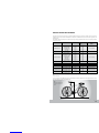 3
3
-
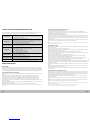 4
4
-
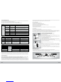 5
5
-
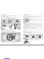 6
6
-
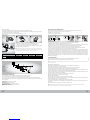 7
7
-
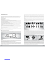 8
8
-
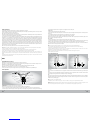 9
9
-
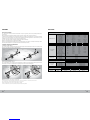 10
10
-
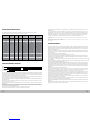 11
11
-
 12
12
-
 13
13
-
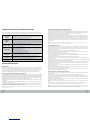 14
14
-
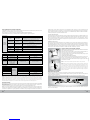 15
15
-
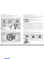 16
16
-
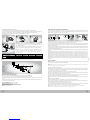 17
17
-
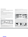 18
18
-
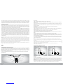 19
19
-
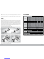 20
20
-
 21
21
-
 22
22
-
 23
23
-
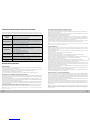 24
24
-
 25
25
-
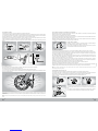 26
26
-
 27
27
-
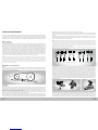 28
28
-
 29
29
-
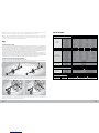 30
30
-
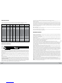 31
31
-
 32
32
-
 33
33
-
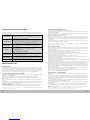 34
34
-
 35
35
-
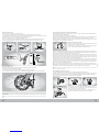 36
36
-
 37
37
-
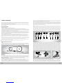 38
38
-
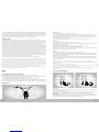 39
39
-
 40
40
-
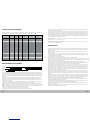 41
41
-
 42
42
-
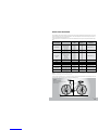 43
43
-
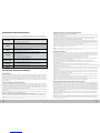 44
44
-
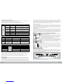 45
45
-
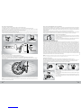 46
46
-
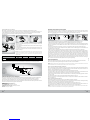 47
47
-
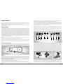 48
48
-
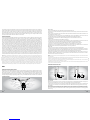 49
49
-
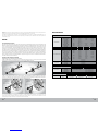 50
50
-
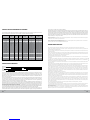 51
51
-
 52
52
-
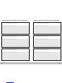 53
53
-
 54
54
-
 55
55


BERG fuego cx series Manual do usuário
- Categoria
- Acessórios para bicicletas
- Tipo
- Manual do usuário
- Este manual também é adequado para
em outras línguas
- español: BERG fuego cx series Manual de usuario
- français: BERG fuego cx series Manuel utilisateur
- Deutsch: BERG fuego cx series Benutzerhandbuch
Outros documentos
-
 URBANGLIDE URBBK12931 Manual do usuário
-
 URBANGLIDE URBBK12928 Manual do usuário
-
Logitech G PRO Load Cell Sim Racing Pedals Guia de usuario
-
Nilox X5 Manual do usuário
-
 URBANGLIDE URBBK12930 Manual do usuário
-
 Youin BK1700 Manual do usuário
-
Manitou Technical Reference 2004 South Manual do proprietário
-
 URBANGLIDE URBBK12915 Manual do usuário
-
Canyon Torque:ON CF Guia rápido
-
BH EMOTION Manual do usuário


