
GRTE18
Operating Instruction
DE/EN/FR/PT/IT/ES/ZH/JA/RU
8016953.16B5
OPERATING INSTRUCTION

Described product
GR18
GRTE18
Manufacturer
SICK AG
Erwin-Sick-Str. 1
79183 Waldkirch
Germany
Production location
Legal information
This work is protected by copyright. Any rights derived from the copyright shall be
reserved for SICK AG. Reproduction of this document or parts of this document is only
permissible within the limits of the legal determination of Copyright Law. Any modifica‐
tion, abridgment or translation of this document is prohibited without the express writ‐
ten permission of SICK AG.
The trademarks stated in this document are the property of their respective owner.
© SICK AG. All rights reserved.
Original document
T
his document is an original document of SICK AG.
2006/42/EC
NO
SAFETY
8016953.16B5 | SICK
Subjec
t to change without notice
1

Photoelectric proximity sensor
Operating instructions
2 Safety notes
■
Read the oper
ating instructions before commissioning.
■
Connection, mounting, and setting may only be performed by trained specialists.
■
Not a safety component in accordance with the EU Machinery Directive. Only for use in appli‐
cations in accordance with NFPA 79. UL-listed adapters with connecting cables are available.
Enclosure type 1
■
When commissioning, protect the device from moisture and contamination.
■
These operating instructions contain information required during the life cycle of the sensor.
3 Correct use
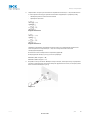
The GRTE18 is an opto-electronic photoelectric proximity sensor (referred to as "sensor" in the
following) f
or the optical, non-contact detection of objects, animals, and persons. If the product is
used for any other purpose or modified in any way, any warranty claim against SICK AG shall
become void.
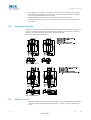
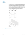
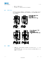
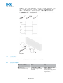
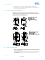
Energetic photoelectric proximity sensor
Image 1: GRTE18-xxxx2
Image 2: GRTE18-xxxx7
Irrtuemer | SICK 1
8016953.16B5

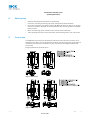
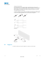
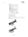
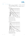
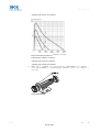
4 Commissioning
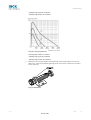
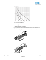
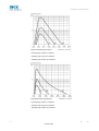
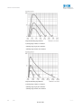
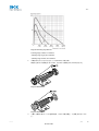
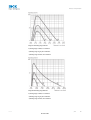
1 Check the application conditions: Adjust the sensing range and the remission capability of
the object according to the corresponding diagram [H] (x = sensing range, y = operating
reserve).
During this process, an object can only be detected in front of a background if the remission
capability of the object is significantly higher than that of the background or if the distance
between the object and the background is sufficiently long.
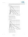
Image 3: H: Sensing range 115 mm
1) Sensing range on black, 6 % r
emission
2) Sensing range on gray, 20 % remission
3) Sensing range on white, 90 % remission
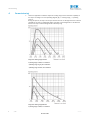
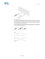
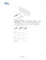
Image 4: H: Sensing range 550 mm
1) Sensing range on black, 6 % r
emission
Commissioning
2 | SICK Irrtuemer
8016953.16B5

2) Sensing range on gray, 20 % remission
3) Sensing range on white, 90 % remission
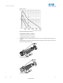
Image 5: H: Sensing range 800 mm
1) Sensing rang
e on blac
k
, 6 % r
emission
2) Sensing range on gray, 20 % remission
3) Sensing range on white, 90 % remission
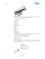
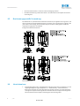
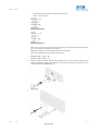
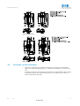
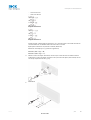
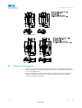
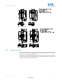
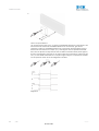
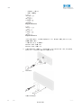
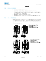
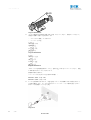
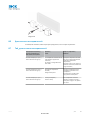
2 Mount the sensor using a suitable mounting bracket (see the SICK range of accessories).
Observe the maximum per
missible tightening torque of the sensor of 2.0 Nm for metal/0.9
Nm for plastic [K].
Image: K: GRTE18-x24x7
Commissioning
Irrtuemer | SICK 3
8016953.16B5

Image: K: GRTE18-x24x2
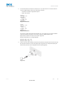
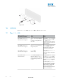
3 The sensors must be connected in a voltage-free state (V
S
= 0 V). The information in t
he gra‐
phics [B] must be observed, depending on the type of connection:
– Male connector connection: pin assignment
– Cable: core color
Image: B: GRTE18-x24xx
Image: B: GRTE18-x11xx
Only apply v
oltage/switch on the power supply (V
S
> 0 V) once all electrical connections have
been completed. The green LED indicator lights up on the sensor.
Explanations of the connection diagram (Graphic B):
Switching outputs Q and /Q (according to Graphic B):
GRTE18-P (PNP: load -> M)
GRTE18-N (NPN: load -> L+)
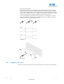
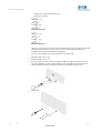
4 Align the sensor with the object. Select the position so that the red emitted light beam hits
the center of t
he object. You must ensure that the optical opening (front screen) of the sen‐
sor is completely clear [E].
Image 6: E
Commissioning
4 | SICK Irrtuemer
8016953.16B5

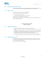
5
Sensor with potentiometer:
The sensitivity (sensing range) is adjus
ted with the potentiometer (type: 270°). Clockwise
rotation: sensitivity (sensing range) increased; counterclockwise rotation: sensitivity (sensing
range) reduced. We recommend placing the switching state in the object, e.g., see Graphic F.
Once the sensitivity has been adjusted, the object is removed from the path of the beam.
The switching output changes (see Graphic C).
The sensor is adjusted and ready for operation. Refer to Graphics C and G to check the func‐
tion. If the switching output fails to behave in accordance with Graphic C, check application
conditions. See section Fault diagnosis.
Image 7: C
Commissioning
Irrtuemer | SICK 5
8016953.16B5

Image 8: G
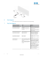
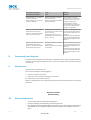
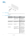
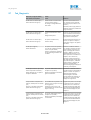
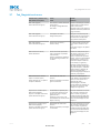
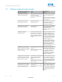
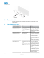
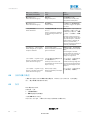
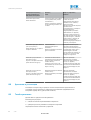
6 Fault diagnosis
Table 7 indicates which measures are to be taken if the sensor stops working.
7 Tab_Fault diagnosis
LED indicator/fault pattern /
LED indicator/fault patt
ern
Cause /
Cause
Measures /
Measures
Green LED does not light up /
Green LED does not light up
N
o voltage or voltage below the
limit values /
No voltage or voltage below the
limit values
Check the power supply, check all
electrical connections (cables and
plug connections) /
Check the power supply, check all
electrical connections (cables and
plug connections)
Green LED does not light up /
Gr
een LED does no
t light up
V
oltage interruptions /
Voltage interruptions
Ensure there is a stable power
supply without interruptions /
Ensure there is a stable power
supply without interruptions
Green LED does not light up /
Green LED does not light up
Sensor is f
aulty /
Sensor is faulty
If the power supply is OK, replace
the sensor /
If the power supply is OK, replace
the sensor
Yellow LED flashes /
Yellow LED f
lashes
Sensor is still ready for operation,
but the operating conditions are
not ideal /
Sensor is still ready for operation,
but the operating conditions are
not ideal
Check the operating conditions:
Fully align the beam of light (light
spot) with the object. / Clean the
optical surfaces / Readjust the
sensitivity (potentiometer) / Check
sensing range and adjust if neces‐
sary, see Graphic E /
Check the operating conditions:
Fully align the beam of light (light
spot) with the object. / Clean the
optical surfaces / Readjust the
sensitivity (potentiometer) /
Check sensing range and adjust if
necessary, see Graphic E
6 | SICK Irrtuemer
8016953.16B5

LED indicator/fault pattern /
LED indicator/fault patter
n
Cause /
Cause
Measures /
Measures
Yellow LED lights up, no object in
t
he pat
h of t
he beam /
Y
ellow LED lights up, no object in
the path of the beam
Remission capability of the back‐
ground is excessive /
Remission capability of the back‐
ground is excessive
Check changes to the back‐
ground. Reduce the sensitivity of
the sensor or use sensors with
background suppression /
Check changes to the back‐
ground. Reduce the sensitivity of
the sensor or use sensors with
background suppression
Object is in the path of the beam,
yellow LED does not light up /
Object is in t
he path of the beam,
yellow LED does not light up
Sensitivity is set too low or dis‐
tance between the sensor and the
object is too long /
Sensitivity is set too low or dis‐
tance between the sensor and the
object is too long
Increase the sensing range, take
note of the distance between the
sensor and the background, see
Graphic E /
Increase the sensing range, take
note of the distance between the
sensor and the background, see
Graphic E
Object is in the path of the beam,
yellow LED does not light up /
Object is in t
he path of the beam,
yellow LED does not light up
Remission capability of the object
is insufficient /
Remission capability of the object
is insufficient
Increase the sensing range, take
note of the distance between the
sensor and the background, see
Graphic E /
Increase the sensing range, take
note of the distance between the
sensor and the background, see
Graphic E
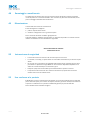
8 Disassembly and disposal
The sensor must be disposed of according to the applicable country-specific regulations. Efforts
should be made during the disposal process t
o recycle the constituent materials (particularly pre‐
cious metals).
9 Maintenance
SICK sensors are maintenance-free.
W
e recommend doing the f
ollowing regularly:
1. Clean the external lens surfaces
2. Check the screw connections and plug-in connections
No modifications may be made to devices.
Subject to change without notice. Specified product properties and technical data are not written
guarantees.
Reflexions-Lichttaster
Betriebsanleitung
12 Sicherheitshinweise
■
Vor der Inbetriebnahme die Be
triebsanleitung lesen.
■
Anschluss, Montage und Einstellung nur durch Fachpersonal.
■
Kein Sicherheitsbauteil gemäß EU-Maschinenrichtlinie. Nur zur Verwendung in Anwendungen
gemäß NFPA 79. Von UL gelistete Adapter mit Anschlusskabeln sind verfügbar. Enclosure
type 1
Disassembly and disposal
Irrtuemer | SICK 7
8016953.16B5

■
Gerät bei Inbetr
iebnahme vor Feuchte und Verunreinigung schützen.
■
Diese Betriebsanleitung enthält Informationen, die während des Lebenszyklus des Sensors
notwendig sind.
13 Bestimmungsgemäße Verwendung
Die GRTE18 ist ein optoelektronischer Reflexions-Lichttaster (im Folgenden Sensor genannt) und
wird zum optischen, berühr
ungslosen Erfassen von Sachen, Tieren und Personen eingesetzt. Bei
jeder anderen Verwendung und bei Veränderungen am Produkt verfällt jeglicher Gewährleis‐
tungsanspruch gegenüber der SICK AG.
Energetischer Reflexionslichttaster
Abb. 9: GRTE18-xxxx2
Abb. 10: GRTE18-xxxx7
14 Inbetriebnahme
1 Einsatzbedingungen prüfen: Schaltabstand und Remissionsvermögen des Objektes mit dem
zug
ehörig
en Diagramm [vgl. H] abgleichen. (x = Schaltabstand, y = Funktionsreserve).
Dabei kann ein Objekt vor einem Hintergrund nur detektiert werden, wenn das Remissions‐
vermögen des Objektes deutlich größer ist als das Remissionsvermögen des Hintergrundes
oder der Abstand zwischen Objekt und Hintergrund ausreichend groß ist.
Sicherheitshinweise
8 | SICK Irrtuemer
8016953.16B5

Abb. 11: H: Sensing range 115 mm
1) Sensing range on black, 6 % r
emission
2) Sensing range on gray, 20 % remission
3) Sensing range on white, 90 % remission
Abb. 12: H: Sensing range 550 mm
1) Sensing range on black, 6 % r
emission
2) Sensing range on gray, 20 % remission
3) Sensing range on white, 90 % remission
Inbetriebnahme
Irrtuemer | SICK 9
8016953.16B5

Abb. 13: H: Sensing range 800 mm
1) Sensing range on black, 6 % r
emission
2) Sensing range on gray, 20 % remission
3) Sensing range on white, 90 % remission
2 Den Sensor an einen geeigneten Befestigungswinkel montieren (siehe SICK-Zubehör-Pro‐
gramm).
Maximal zulässiges Anzugsdrehmoment des Sensor
s von 2,0 Nm für Metall / 0,9 Nm für
Kunststoff beachten [vgl. K].
Abb.: K: GRTE18-x24x7
Abb.: K: GRTE18-x24x2
Inbetriebnahme
10 | SICK Irrtuemer
8016953.16B5

3 Anschluss der Sensoren muss spannungsfrei (V
S
= 0 V) erfolgen. Je nach Anschlussart sind
die Informationen in den Grafiken [vgl. B] zu beachten:
– Steckeranschluss: Pinbelegung
– Leitung: Adernfarbe
Abb.: B: GRTE18-x24xx
Abb.: B: GRTE18-x11xx
Erst nac
h Anschluss aller elektrischen Verbindungen die Spannungsversorgung (V
S
> 0 V)
anlegen bzw. einschalten. Am Sensor leuchtet die grüne Anzeige-LED.
Erläuterungen zum Anschlussschema (Grafik B):
Schaltausgänge Q bzw. /Q (gemäß Grafik B):
GRTE18-P (PNP: Last -> M)
GRTE18-N (NPN: Last -> L+)
4 Sensor auf Objekt ausrichten. Positionierung so wählen, dass der rote Sendelichtstrahl in
der Mitte des Objekts auftr
ifft. Es ist darauf zu achten, dass die optische Öffnung (Front‐
scheibe) des Sensors vollständig frei ist [vgl. E].
Abb. 14: E
Inbetriebnahme
Irrtuemer | SICK 11
8016953.16B5

5
Sensor mit Potentiometer:
Mit dem Pot
entiometer (Art: 270°) wird die Empfindlichkeit (Schaltabstand) eingestellt. Dre‐
hung nach rechts: Erhöhung der Empfindlichkeit (Schaltabstand), Drehung nach links: Ver‐
ringerung der Empfindlichkeit (Schaltabstand). Wir empfehlen, den Schaltabstand in das
Objekt zu legen, z.B. siehe Grafik F. Nachdem die Empfindlichkeit eingestellt worden ist, das
Objekt aus dem Strahlengang entfernen. Der Schaltausgang ändert sich (siehe Grafik C).
Sensor ist eingestellt und betriebsbereit. Zur Überprüfung der Funktion Grafik C und G
heranziehen. Verhält sich der Schaltausgang nicht gemäß Grafik C, Einsatzbedingungen prü‐
fen. Siehe Abschnitt Fehlerdiagnose.
Abb. 15: C
Inbetriebnahme
12 | SICK Irrtuemer
8016953.16B5

Abb. 16: G
16 Fehlerdiagnose
Tabelle 17 zeigt, welche Maßnahmen durchzuführen sind, wenn die Funktion des Sensors nicht
mehr g
egeben is
t.
17 Tab_Fehlerdiagnose
Anzeige-LED / Fehlerbild /
LED indicator/fault pattern
Ursache /
Cause
Maßnahme /
Measures
grüne LED leuchtet nicht /
Green LED does not light up
k
eine Spannung oder Spannung
unterhalb der Grenzwerte /
No voltage or voltage below the
limit values
Spannungsversorgung prüfen,
den gesamten elektrischen
Anschluss prüfen (Leitungen und
Steckerverbindungen) /
Check the power supply, check all
electrical connections (cables and
plug connections)
grüne LED leuchtet nicht /
Green LED does not light up
Spannungsunt
erbrechungen /
Voltage interruptions
Sicherstellen einer stabilen Span‐
nungsversorgung ohne Unterbre‐
chungen /
Ensure there is a stable power
supply without interruptions
grüne LED leuchtet nicht /
Green LED does not light up
Sensor is
t defekt /
Sensor is faulty
Wenn Spannungsversorgung in
Ordnung ist, dann Sensor austau‐
schen /
If the power supply is OK, replace
the sensor
gelbe LED blinkt /
Yellow LED f
lashes
Sensor ist noch betriebsbereit,
aber die Betriebsbedingungen
sind nicht optimal /
Sensor is still ready for operation,
but the operating conditions are
not ideal
Betriebsbedingungen prüfen:
Lichtstrahl (Lichtfleck) vollständig
auf das Objekt ausrichten / Reini‐
gung der optischen Flächen /
Empfindlichkeit (Potentiometer)
neu einstellen / Schaltabstand
überprüfen und ggfs. anpassen,
siehe Grafik E /
Check the operating conditions:
Fully align the beam of light (light
spot) with the object. / Clean the
optical surfaces / Readjust the
sensitivity (potentiometer) /
Check sensing range and adjust if
necessary, see Graphic E
Irrtuemer | SICK 13
8016953.16B5

Anzeige-LED / Fehlerbild /
LED indicator/fault patter
n
Ursache /
Cause
Maßnahme /
Measures
gelbe LED leuchtet, kein Objekt im
Strahleng
ang /
Y
ello
w LED lights up, no object in
t
he path of the beam
Remissionsvermögen des Hinter‐
grundes zu hoch /
Remission capability of the back‐
ground is excessive
Veränderungen des Hintergrundes
prüfen. Empfindlichkeit des Sen‐
sors reduzieren oder Taster mit
Hintergrundausblendung verwen‐
den /
Check changes to the back‐
ground. Reduce the sensitivity of
the sensor or use sensors with
background suppression
Objekt ist im Strahlengang, gelbe
LED leuchtet nic
ht /
Object is in the path of the beam,
yellow LED does not light up
Empfindlichkeit ist zu gering ein‐
gestellt oder Abstand zwischen
Sensor und Objekt ist zu groß /
Sensitivity is set too low or dis‐
tance between the sensor and the
object is too long
Schaltabstand vergrößern,
Abstand zwischen Sensor und
Hintergrund beachten, siehe Gra‐
fik E /
Increase the sensing range, take
note of the distance between the
sensor and the background, see
Graphic E
Objekt ist im Strahlengang, gelbe
LED leuchtet nic
ht /
Object is in the path of the beam,
yellow LED does not light up
Remissionsvermögen des Objek‐
tes ist zu gering /
Remission capability of the object
is insufficient
Schaltabstand vergrößern,
Abstand zwischen Sensor und
Hintergrund beachten, siehe Gra‐
fik E /
Increase the sensing range, take
note of the distance between the
sensor and the background, see
Graphic E
18 Demontage und Entsorgung
Die Entsorgung des Sensors hat gemäß den länderspezifisch anwendbaren Vorschriften zu erfol‐
gen. Für die enthaltenen W
ertstoffe (insbesondere Edelmetalle) ist im Rahmen der Entsorgung
eine Verwertung anzustreben.
19 Wartung
SICK-Sensoren sind wartungsfrei.
W
ir empfehlen, in r
egelmäßigen Abständen
1. die optischen Grenzflächen zu reinigen
2. Verschraubungen und Steckverbindungen zu überprüfen
Veränderungen an Geräten dürfen nicht vorgenommen werden.
Irrtümer und Änderungen vorbehalten. Angegebene Produkteigenschaften und technische Daten
stellen keine Garantieerklärung dar.
Détecteur à réflexion directe
Notice d'instruction
22
Consignes de sécurité
■
Lire la notice d'instr
uction avant la mise en service.
■
Confier le raccordement, le montage et le réglage uniquement à un personnel spécialisé.
Demontage und Entsorgung
14 | SICK Irrtuemer
8016953.16B5

■
Il ne s'agit pas d'un composant de sécurit
é au sens de la directive machines CE. Utilisation
uniquement pour des applications selon la NFPA 79 Des adaptateurs listés UL avec câbles
de connexion sont disponibles. Enclosure type 1
■
Protéger l'appareil contre l'humidité et les impuretés lors de la mise en service.
■
Cette notice d'instruction contient des informations nécessaires pendant toute la durée de
vie du capteur.
23 Utilisation conforme
GRTE18 est un détecteur à réflexion directe optoélectronique (appelé capteur dans ce document)
qui perme
t la détection optique sans contact d'objets, d'animaux et de personnes. Toute autre
utilisation ou modification du produit annule la garantie de SICK AG.
Détecteur énergétique à réflexion directe
Image 17: GRTE18-xxxx2
Image 18: GRTE18-xxxx2
24 Mise en service
1 Vérifier les conditions d'utilisation : comparer la portée et les caractéristiques de réflectivité
de l'obje
t à l'aide du diagr
amme [E] correspondant. (x = portée, y = réserve de fonctionne‐
ment).
Consignes de sécurité
Irrtuemer | SICK 15
8016953.16B5

Ce faisant, il n'est possible de détecter un objet devant un arrière-plan que si les caractéris‐
tiques de réflectivité de l'objet sont largement supérieures à celles de l'arrière-plan en ques‐
tion ou si la distance entre l'objet et l'arrière-plan est suffisante.
Image 19: H: Sensing range 115 mm
1) Sensing range on black, 6 % r
emission
2) Sensing range on gray, 20 % remission
3) Sensing range on white, 90 % remission
Image 20: H: Sensing range 550 mm
1) Sensing range on black, 6 % r
emission
2) Sensing range on gray, 20 % remission
3) Sensing range on white, 90 % remission
Mise en service
16 | SICK Irrtuemer
8016953.16B5

Image 21: H: Sensing range 800 mm
1) Sensing range on black, 6 % r
emission
2) Sensing range on gray, 20 % remission
3) Sensing range on white, 90 % remission
2 Monter le capteur sur une équerre de fixation adaptée (voir la gamme d'accessoires SICK).
Respecter le couple de serr
age maximal admissible du capteur de 2,0 Nm pour métal / 0,9
Nm pour plastique [voir K].
Image: K: GRTE18-x24x7
Image: K: GRTE18-x24x2
3 Le raccordement des capteurs doit s'effectuer hors tension (V
S
= 0 V). Selon le mode de rac‐
cordement, respecter les informations contenues dans les schémas [B] :
Mise en service
Irrtuemer | SICK 17
8016953.16B5

– Raccordement du connecteur : affectation des broches
– Câble : couleur des fils
Image: B: GRTE18-x24xx
Image: B: GRTE18-x11xx
Après av
oir terminé tous les raccordements électriques, enclencher l'alimentation électrique
(V
S
> 0 V). La DEL verte s'allume sur le capteur.
Explications relatives au schéma de raccordement (schéma B) :
Sorties de commutation Q ou /Q (selon le schéma B) :
GRTE18-P (PNP : charge -> M)
GRTE18-N (NPN : charge -> L+)
4 Aligner le capteur sur l'objet. Sélectionner la position de sorte que le faisceau lumineux émis
rouge t
ouche l'objet en plein milieu. S'assurer que l'ouverture optique (vitre frontale) du cap‐
teur est parfaitement dégagée [voir E].
Image 22: E
5
Mise en service
18 | SICK Irrtuemer
8016953.16B5
A página está carregando...
A página está carregando...
A página está carregando...
A página está carregando...
A página está carregando...
A página está carregando...
A página está carregando...
A página está carregando...
A página está carregando...
A página está carregando...
A página está carregando...
A página está carregando...
A página está carregando...
A página está carregando...
A página está carregando...
A página está carregando...
A página está carregando...
A página está carregando...
A página está carregando...
A página está carregando...
A página está carregando...
A página está carregando...
A página está carregando...
A página está carregando...
A página está carregando...
A página está carregando...
A página está carregando...
A página está carregando...
A página está carregando...
A página está carregando...
A página está carregando...
A página está carregando...
A página está carregando...
A página está carregando...
A página está carregando...
A página está carregando...
A página está carregando...
A página está carregando...
A página está carregando...
A página está carregando...
A página está carregando...
A página está carregando...
A página está carregando...
A página está carregando...
A página está carregando...
A página está carregando...
-
 1
1
-
 2
2
-
 3
3
-
 4
4
-
 5
5
-
 6
6
-
 7
7
-
 8
8
-
 9
9
-
 10
10
-
 11
11
-
 12
12
-
 13
13
-
 14
14
-
 15
15
-
 16
16
-
 17
17
-
 18
18
-
 19
19
-
 20
20
-
 21
21
-
 22
22
-
 23
23
-
 24
24
-
 25
25
-
 26
26
-
 27
27
-
 28
28
-
 29
29
-
 30
30
-
 31
31
-
 32
32
-
 33
33
-
 34
34
-
 35
35
-
 36
36
-
 37
37
-
 38
38
-
 39
39
-
 40
40
-
 41
41
-
 42
42
-
 43
43
-
 44
44
-
 45
45
-
 46
46
-
 47
47
-
 48
48
-
 49
49
-
 50
50
-
 51
51
-
 52
52
-
 53
53
-
 54
54
-
 55
55
-
 56
56
-
 57
57
-
 58
58
-
 59
59
-
 60
60
-
 61
61
-
 62
62
-
 63
63
-
 64
64
-
 65
65
-
 66
66


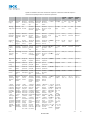
em outras línguas
- español: SICK GRTE18 Instrucciones de operación
- français: SICK GRTE18 Mode d'emploi
- English: SICK GRTE18 Operating instructions
- 日本語: SICK GRTE18 取扱説明書
Artigos relacionados
-
SICK GRTE18 Instruções de operação
-
-
-
-
-
-
-
-
SICK WT100-2 energetic Instruções de operação
-