
3067/70-13T
MODE D’EMPLOI
GEBRAUCHSANWEISUNG
INSTRUCCIONES
GEBRUIKSAANWIJZING
,16758.&-$2%6á8*,
ISTRUZIONI PER L’USO
INSTRUCTIONS FOR USE
INSTRUÇÕES DE USO
HASZNÁLATI ÚTMUTATÓ
I
D
NL
EN
E
PL
F
PT
HU

2
BETA UTENSILI S.p.A.
Via Alessandro Volta, 18
20845 Sovico (MB) ITALY
Tel. +39 039.2077.1 - Fax +39 039.2010742
www.beta-tools.com
- DICHIARAZIONE DI CONFORMITÀ
- DECLARATION OF CONFORMITY
- DÉCLARATION DE CONFORMITÉ
- KONFORMITÄTSERKLÄRUNG
- DECLARACIÓN DE CONFORMIDAD
- DECLARAÇÃO DE CONFORMIDADE
- VERKLARING VAN CONFORMITEIT
'(./$5$&-$=*2'12Ğ&,
0(*)(/(/Ę6e*,1<,/$7.2=$7
2JQLLQWHUYHQWRRPRGLÀFDQRQDXWRUL]]DWLGDOOD%(7$87(16,/,IDUDQQRGHFDGHUHODYDOLGLWjGLTXHVWDGLFKLDUD]LRQH
$Q\WDPSHULQJRUFKDQJHXQDXWKRUL]HGE\%(7$87(16,/,VKDOOLPPHGLDWHO\LQYDOLGDWHWKLVVWDWHPHQW
7RXWHRSpUDWLRQRXPRGLÀFDWLRQQRQDXWRULVpHVSDU%(7$87(16,/,IHURQWGpFKRLUODYDOLGLWpGHFHWWHGpFODUDWLRQ
(LQJULIIHXQGbQGHUXQJHQRKQHGLH*HQHKPLJXQJYRQ%(7$87(16,/,PDFKHQGLHYRUOLHJHQGH(UNOlUXQJXQJOWLJ
&XDOTXLHULQWHUYHQFLyQRPRGLÀFDFLyQQRDXWRUL]DGDVSRU%(7$87(16,/,DQXODUiQODYDOLGH]GHHVWDGHFODUDFLyQ
4XDOTXHULQWHUYHQomRRXPRGLÀFDomRTXHQmRVHMDDXWRUL]DGDSHOD%(7$87(16,/,DQXODUjDYDOLGDGHGHVWDGHFOUDomR
/HGHUHQLHWGRRU%(7$87(16,/,JHDXWRULVHHUGHLQJUHHSRIZLM]LJLQJGRHWGHJHOGLJKHLGYDQGH]HYHUNODULQJYHUYDOOHQ
- -DNDNROZLHNLQJHUHQFMDOXE]PLDQDQLHDXWRU\]RZDQDSU]H]%(7$87(16,/,QDW\FKPLDVWXQLHZDīQLDWRRğZLDGF]HQLH
0LQGHQD%(7$87(16,/,iOWDOQHPIHOKDWDOPD]RWWEHDYDWNR]iVYDJ\PyGRVtWiVpUYpQ\WHOHQtWLH]WDQ\LODWNR]DWRW
- Si dichiara che l’apparecchio tipo
- We hereby state that the machine type
- On déclare que la machine type
- Wir erklären, dass das Gerät Typ
- Declara que el aparato tipo
- Declara-se que a máquina tipo
- Verklaard wordt dat het apparaat type
1LQLHMV]\PRĞZLDGF]DP\ĪHXU]ąG]HQLHW\SX
-
Kimondja, hogy a berendezés típusát
}
۸
}
è conforme alle norme
LVLQFRPSOLDQFHZLWKWKHUXOOV
est conforme aux normes
den Normen entspricht
es conforme a las normas
é conforme as normas
overeenkomstig de richtlijnen
jest zgodne z zasady
megfelel a szabályok
2006/42/CE
2006/42/EEC
UNI EN1494
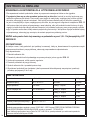
MILANO
MODEL 3067/70-13T

3
ISTRUZIONI PER L’USO
I
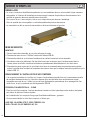
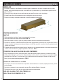
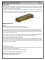
ART. 3067/70-13T SOLLEVATORE OLEOPNEUMATICO
PREMESSA
Gentile Cliente, prima di utilizzare il sollevatore leggere attentamente le presenti istruzioni e familiarizzare con i
simboli di sicurezza.
- Il presente libretto è parte integrante della macchina, deve essere conservato con cura ed essere a disposizione
dell’operatore per ogni ulteriore consultazione.
- I contenuti di questo libretto sono conformi alla Direttiva Macchine 98/37/CEE e omologato secondo la normativa
HXURSHD(1HVXFFHVVLYHPRGL¿FKH
/DGLWWDFRVWUXWWULFHVLULVHUYDLOGLULWWRGLHIIHWWXDUHPRGL¿FKHVHQ]DSUHDYYLVRHVHQ]DLQFRUUHUHLQVDQ]LRQHDOFX
na, ferme restando le caratteristiche tecniche principali e di sicurezza.
- Il mancato rispetto delle istruzioni contenute in questo manuale può causare lesioni personali anche mortali.
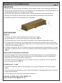
- Il costruttore declina ogni responsabilità di danni, a persone o cose, causati dall’uso errato o improprio del suo
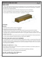
SURGRWWR/DWDUJDGLLGHQWL¿FD]LRQHqSRVWDVXO¿DQFRGHOFDUWHUDIS. 1
NORME DI SICUREZZA
- L’uso dell’attrezzatura è consentito esclusivamente a personale autorizzato, che sia a conoscenza del contenuto
del presente libretto di uso e manutenzione.
-Il cricco è esclusivamente uno strumento di sollevamento e non di sostegno, è quindi assolutamente proibito
ODYRUDUHRGRSHUDUHLQTXDOVLDVLPDQLHUDVRWWRDOPH]]RFKHVLVWDVROOHYDQGR¿QWDQWRFKHORVWHVVRQRQVLD
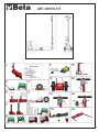
collocato sugli appositi cavalletti di sostegno. DIS. 2
- Prima di procedere ad una operazione di sollevamento, occorre bloccare l’autoveicolo con il freno di staziona
PHQWRHRSRQHQGRGXHFXQHLLQFRUULVSRQGHQ]DGHOOHUXRWHFRPHLOOXVWUDWRLQ¿JXUDDIS. 3
,QIDVHGLVROOHYDPHQWRVHLOYHLFRORqFDULFRYHUL¿FDUHODVWDELOLWjGHOFDULFR
- Collocare il sollevatore in modo che il carico sia centrato su di esso e in corrispondenza degli appositi punti di
presa indicati dal costruttore del veicolo. DIS. 4
- Durante le operazioni di sollevamento e di discesa occorre accertarsi che non vi siano persone ed animali sotto
il carico sospeso o nelle vicinanze.
- Prima di abbassare il carico, occorre accertarsi che il manubrio sia nella posizione orizzontale. DIS. 5
- Non sollevare mai carichi su terreni in pendenza, non piani o cedevoli. DIS. 6
- Fare uso esclusivamente delle prolunghe fornite dal costruttore in dotazione alla macchina. Non fare uso
delle prolunghe senza l’apposito piattello. Non utilizzare mai più di due prolunghe. DIS. 7
- Non sollevare il carico in spazi ristretti per non correre il rischio di intrappolamento. DIS. 8
- E’ vietato utilizzare più sollevatori contemporaneamente sullo stesso carico.
- Non manomettere in alcun caso la valvola di sovrapressione dotata di sigillo di garanzia. DIS. 9

4
ISTRUZIONI PER L’USO
I
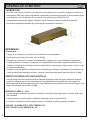
IMBALLAGGIO
- Il corpo, il manico e le varie parti del sollevatore vengono imballate in un cartone tripla onda con pallet; inoltre si
WURYHUDQQRDOO¶LQWHUQRGHOO¶LPEDOODJJLRDQFKHLOPDQXDOHXVRHPDQXWHQ]LRQHHGLOFHUWL¿FDWRGLJDUDQ]LDLQXQD
carpetta apposita.
- Sul cartone del sollevatore è presente e ben visibile l’indicazione di non capovolgere l’imballo.
- A seconda della quantità dei sollevatori spediti vengono utilizzati pallet con diverse dimensioni.
- La movimentazione avviene tramite transpallet o muletti a forche.
MESSA IN SERVIZIO
MONTAGGIO
1. Estrarre il manubrio, il sollevatore e le prolunghe dai cartoni.
2. Svitare dall’interno del telaio i due dadi. DIS. 10
3. Svitare dal telaio la vite avendo l’accortezza di mantenerli assemblati.
4. Inserire il manubrio (il distributore dell’ aria deve essere rivolto verso i pistoni) con l’innesto nell’apposita sca
nalatura, inserire i particolari precedentemente smontati nel foro del manubrio, avvitare la vite e successivamen
te serrare con il dado
5. Collegare i due tubi dell’aria che escono dal manubrio negli appositi innesti rapidi nel telaio rispettando i colori
come indicati dall’adesivo presente sul telaio stesso. DIS. 11
ALLACCIAMENTO CON L’IMPIANTO DI ARIA COMPRESSA
- L’aria compressa entra nel circuito del cricco attraverso l’innesto rapido posto sul comando manuale di alzata e
discesa del cricco; occorre quindi disporre di un tubo di collegamento con un innesto rapido compatibile con quello
del cricco. Controllare che il tubo di alimentazione dell’aria abbia un passaggio utile di almeno 6mm, e che non
vi siano strozzature. DIS. 12
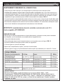
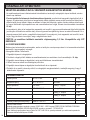
3UHVVLRQHGLDOLPHQWD]LRQHEDU
- Non immettere assolutamente nel circuito di aria compressa: olio idraulico o di vaselina, liquido per freni, petrolio
o altri liquidi.
,QVHULUHQHOO¶LPSLDQWRGLDULDFRPSUHVVDXQJUXSSR¿OWURGHXPLGL¿FDWRUHOXEUL¿FDWRUH
6HVLYXROHOXEUL¿FDUHLOFLUFXLWRGLDULDFRPSUHVVDXVDUHHVFOXVLYDPHQWH
AGIP OSO 100; MOBIL DTE 27; ESSO TERESSO 100;
SHELL TELLUS 100; BP ENERGOL HP 100

5
ISTRUZIONI PER L’USO
I
UTILIZZO
,03257$17(,OFULFFRGHYHHVVHUHREEOLJDWRULDPHQWHXWLOL]]DWRRD]LRQDWRLQSRVL]LRQHRUL]]RQWDOH
SHUQRQFRPSURPHWWHUQHLOIXQ]LRQDPHQWR
- Rispettare tassativamente le norme di sicurezza descritte in questo manuale.
1. Posizionare il cricco sotto il punto di appoggio previsto come indicato sul manuale del costruttore del mezzo.
La ditta costruttrice declina ogni responsabilità per qualsiasi rottura del mezzo sollevato ed a danni a persone
o cose dovute ad un utilizzo sbagliato del sollevatore stesso.
2. La leva di posizionamento del manico (1) si trova a sinistra rispetto all’operatore, trasladola verso l’alto si
libera il sistema di arresto consentendo all’operatore di scegliere una delle tre posizioni possibili del manico.DIS.13
3. Quando il comando (2) è in posizione perfettamente centrale il cric si trova in stato di riposo.
4. Ruotando il comando (2) posto in prossimità del manubrio verso destra rispetto all’operatore, il cricco solleva
il carico.
5. Ruotando il comando (2) posto in prossimità del manubrio verso sinistra rispetto all’operatore, il carico scende.
DIS.13
6. Dopo aver sollevato il carico, è assolutamente indispensabile appoggiarlo sugli appositi cavalletti di sostegno,
prima di effettuare qualsiasi operazione sotto al mezzo.
RICORDA! IL CRICCO E’ UN APPARECCHIO DI SOLLEVAMENTO E NON DI SOSTEGNO!
- Il datore di lavoro dell’operatore dovrà provvedere all’addestramento necessario ed a fornire l’informazione
necessaria per ciò che concerne le forze di pompaggio e di traslazione.
,QFDVRGLURWWXUDGHOGLVWULEXWRUHGXUDQWHO¶XWLOL]]RLQWHUYHQLUHGLUHWWDPHQWHVXOÀXVVRG¶DULDFKLXGHQGRLOUXELQHWWR
di sicurezza posto tra l’innesto rapido dell’ingresso dell’aria e il distributore stesso. DIS. 14
- 3ULPDGLRSHUDUHFRQLOVROOHYDWRUHqFRQVLJOLDWRFRPSLHUHDOFXQHRSHUD]LRQLDYXRWRDOÀQHGLDFTXLVWDUH
ODVHQVLELOLWjQHFHVVDULDSHURSHUDUHLQVLFXUH]]DFRQLOFULFFR
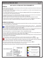
USI IMPROPRI
Il sollevatore oleopneumatico è stato progettato e costruito per sollevare mezzi di trasporto. Ogni altro uso del cricco,
FRPHDGHVHPSLRLOVROOHYDPHQWRHRORVSRVWDPHQWRGLSHUVRQHVLFRQ¿JXUDFRPHDVVROXWDPHQWHLPSURSULR2JQL
XWLOL]]RGHOFULFFRQRQFRQIRUPHDOOHQRUPHGLVLFXUH]]DHOHQFDWHLQTXHVWRPDQXDOHVLFRQ¿JXUDFRPHXVRLPSURSULR
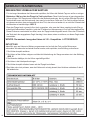
ACCESSORI
- La macchina viene fornita di due prolunghe o adattatori di altezza (prolunga lunga 120mm, prolunga corta 70mm)
un piattello a dentini circolari (piattello 10mm) e un portaprolunghe.
NON UTILIZZARE MAI PIU’ DI DUE PROLUNGHE! OGNI DANNO DERIVATO DALLA MANCATA OSSERVAZIONE
DELLE SUDDETTE INDICAZIONI NON SARA’ ADDEBITABILE AL COSTRUTTORE E COMPORTERA’ LA DECA-
DENZA DELLE CONDIZIONI DI GARANZIA!
ROTTAMAZIONE E SMALTIMENTO
/RVPDOWLPHQWRGHLOXEUL¿FDQWLGHYHHVVHUHHIIHWWXDWRLQFRQIRUPLWjFRQOHOHJJLDQWLQTXLQDPHQWRLQYLJRUH
- La rottamazione del cricco e delle parti che lo compongono dovrà essere effettuata dall’utilizzatore secondo le
disposizioni vigenti.

6
ISTRUZIONI PER L’USO
I
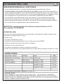
MANUTENZIONE RISERVATA ALL’UTENTE FINALE
- Per una lunga durata del cricco, si consiglia di pulire esternamente ogni quindici giorni i pistoni.
- &RQWUROODUHDOPHQRYROWHDOO·DQQRLOOLYHOORGHOO·ROLRQHOVHUEDWRLR questo controllo deve essere fatto con
LSLVWRQLFRPSOHWDPHQWHDEEDVVDWL,OOLYHOORGHOO¶ROLRGHYHHVVHUHDOO¶DOWH]]DGHOEXOORQFLQRFKHVLWURYDVXO¿DQFR
del cilindro/serbatoio, svitandolo si può controllare. Nel caso si dovesse aggiungere dell’olio nel serbatoio,accertarsi
che sia compatibile con l’olio già presente per non compromettere l’integrità della macchina. DIS. 15
- Se il livello dell’olio è più alto del previsto anche di poco, oppure se il cricco è stato capovolto (succede
facilmente durante il trasporto), l’olio viene espulso attraverso il depressore sotto forma di nebbia. Questo
fenomeno sparisce da solo quando il livello dell’olio si è ripristinato. Se l’olio all’interno del serbatoio supera di
molto il livello indicato è consigliabile toglierne per ripristinare tale livello.
,03257$17(ODTXDQWLWjPDVVLPDGLROLRFRQWHQXWRLQTXHVWRVROOHYDWRUHqGL/
2OLRFRPSDWLELOH$7)'(;521,,'
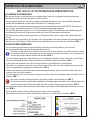
SPURGO DELL’ARIA
Ogni volta che viene fatta manutenzione sul cricco smontando e rimontando parti collegate al serbatoio e alla
motopompa è consigliato eseguire lo spurgo.
Fasi dello spurgo:
1. Fare uscire completamente i pistoni.
5RYHVFLDUHLOFULFFRVXOSLVWRQHIDFHQGROHYDFRQLOPDQLFRFRPHLQ¿JXUDDIS. 16
$]LRQDUHODGLVFHVD¿QWDQWRFKHLOSLVWRQHULHQWULFRQUHJRODULWj
4. Riportare il cricco in posizione di lavoro.
5. Fare entrare completamente il pistone e controllare il livello dell’olio.
6.Provare il cricco senza carico e se la discesa del pistone è a scatti ripetere la procedura per almeno 2 o 3 volte.

7
INSTRUCTIONS FOR USE
EN
ART. 3067/70-13T AIR-HYDRAULIC JACK
FOREWORD
Dear Customer, before using the jack, carefully read these instructions and become acquainted with the safety
symbols.
- This handbook is an integral part of the machine which must be kept safely and be handy for the worker to
consult whenever needed.
- The contents of this manual comply with Machine Directive 98/37 EEC and the jack is type approved in
conformity with the European Norm EN 1494 and following amendments.
7KHPDQXIDFWXULQJFRPSDQ\UHVHUYHVWKHULJKWWRPDNHPRGL¿FDWLRQVZLWKRXWSULRUQRWLFHDQGZLWKRXWLQFXUULQJ
any sanctions whatsoever, without prejudice to the safety and main technical characteristics.
- Failure to observe the instructions may cause personal injury, which in some cases may be mortal.
- Il costruttore declina ogni responsabilità di danni, a persone o cose, causati dall’uso errato o improprio del suo
SURGRWWR/DWDUJDGLLGHQWL¿FD]LRQHqSRVWDVXO¿DQFRGHOFDUWHUDIS. 1
SAFETY REGULATIONS
- Only authorised personnel are allowed to use the equipment and they must know the contents of this
operating and maintenance handbook.
-The jack is an apparatus for lifting only and not for supporting, it is therefore absoltely forbidden to
work in any way under the vehicle being lifted until it is placed on the relative stands. DWG. 2
- Before starting to lift a vehicle it has to be blocked with the parking brake and/or by putting wedges
XQGHUWKHZKHHOVDVLOOXVWUDWHGLQ¿JXUHDWG. 3
- If the vehicle is loaded check load stability when lifting.
- Place the jack so that the load is centred over it and where the gripping points are indicated by the vehicle
manufacturer. DWG. 4
- During lifting and lowering, it is necessary to check there are no persons or animals under the suspended load
or in the vicinity.
- Before lowering the load make certain the handle is in the horizontal position. DWG. 5
- Never lift loads on sloping, uneven or soft ground. DWG. 6
- If extensions are needed use only those supplied by the manufacturer with the jack.
Do not use extensions without the relevant plate. Never use more than two extensions. DWG. 7
'RQRWOLIWWKHORDGLQDFRQ¿QHGVSDFHVRDVQRWWRUXQWKHULVNRIJHWWLQJWUDSSHGDWG. 8
- It is forbidden to use more than one jack simultaneously on the same load.
- Never tamper with the pressure relief valve that has the guarantee seal. DWG. 9

8
INSTRUCTIONS FOR USE
EN
PACKING
- The body, handle and other parts of the jack are packed in a three-layer corrugated cardboard box with pallet;
WKHRSHUDWLQJDQGPDLQWHQDQFHPDQXDOSOXVWKHZDUUDQW\FHUWL¿FDWHLQDIROGHUDUHDOVRLQVLGHWKHER[
- The instruction “Keep upright” is clearly visible on the cardboard box containing the jack.
- Depending on the number of jacks shipped, pallets of different sizes are used.
- Either transpallets or forklift-trucks are used for handling.
PUTTING INTO OPERATION
ASSEMBLY
1. Take the handle, the jack and the extensions out of the cardboard box.
2. Loosen the two nutsfrom inside the chassis. DWG.10
3.Loosen screw from the chassis and remove keeping them assembled.
4.Fit the handle (the air distributor must be facing the pistons) inserting the coupling in the groove, put the parts
removed previously into the hole of the handle, tighten screw and then tighten nut.
5. Connect the two air pipes between the jack and the handle with the quick couplings on the chassis
respecting the colour indication as showed on the sticker on the chassis itself. DWG. 11
CONNECTION TO THE COMPRESSED AIR SYSTEM
- Compressed air enters into the jack circuit through the quick coupling on the top of the manual lifting/
descending controls; it is therefore necessary to have a connecting pipe with a quick coupling compatible with
that of the jack. Check that the air supply pipe has a useful passage of at least 6 mm and it is not pinched or
restricted anywhere. DWG. 12
:25.,1*$,535(6685(%$5
- Absolutely never put the following into the compressed air circuit: hydraulic or Vaseline oil, brake liquid, kerosene
or other liquids.
,QVWDOOD¿OWHUGHKXPLGL¿HUOXEULFDWRUXQLWLQWKHFRPSUHVVHGDLUV\VWHP
- If you want to lubricate the compressed air circuit use exclusively:
AGIP OSO 100; MOBIL DTE 27; ESSO TERESSO 100;
SHELL TELLUS 100; BP ENERGOL HP 100

9
INSTRUCTIONS FOR USE
EN
USE
,03257$177KHMDFNPXVWEHXVHGDQGRSHUDWHGLQWKHKRUL]RQWDOSRVLWLRQRQO\LQRUGHU
not to compromise its operation.
- Expressly observe the safety rules already described in this manual.
1. Position the jack under the supports as described in the manual of the vehicle
the manufacturing company is not responsible for any break or damage to the lifted vehicle or to persons or
property due to an incorrect use of the jack.
2. The handle positioning lever (1) is on the left in relation to the worker; by moving it upwards the stopping system is
released so the worker can then choose one of the three possible handle positions. DWG. 13
3. When control (2) is in the perfectly central position, the jack is in the idle status.
4. By turning control 2, located near the handle, towards the right in relation to the worker, the jack lifts the load.
5. By turning control B, located near the handle, towards the left in relation to the worker, the jack lowers the
load. DWG. 13
6. After lifting the load, it is absolutely essential to rest it on the support stands before doing any work under it.
REMEMBER THAT THE JACK IS A LIFTING DEVICE AND NOT A SUPPORTING DEVICE!!!
- The operator’s employer will have to provide the necessary training and furnish the necessary information about the
pumping and shifting forces.
,IWKHGLVWULEXWRUEUHDNVGXULQJXVHZRUNGLUHFWO\RQWKHÀRZRIDLUFORVLQJWKHVDIHW\FRFNQREHWZHHQWKHTXLFN
coupling of the air inlet and the distributor itself. DWG. 14
- %HIRUHZRUNLQJZLWKWKHMDFNLWLVDGYLVDEOHWRSHUIRUPDIHZRSHUDWLRQVZLWKQRORDGLQRUGHUWRDFTXLUHWKH
VHQVLWLYLW\QHFHVVDU\WRZRUNVDIHO\ZLWKWKHMDFN
IMPROPER USE
The air-hydraulic jack has been designed and made to lift transport vehicles. Any other use of the jack, such as for
LQVWDQFHOLIWLQJDQGRUPRYLQJSHUVRQVLVFRQVLGHUHGWREHGH¿QLWHO\LPSURSHU$OOXVHRIWKHMDFNQRWLQFRQIRUPLW\
with the safety rules listed in this manual is considered to be improper use.
ACCESSORIES
- The jack is supplied with two extensions or height adapters (120 mm the long extension, 70 mm the short
extension), a circular tooth plate (10 mm plate) and an extension holder.
1(9(586(025(7+$17:2(;7(16,2167+(0$18)$&785(5,6127/,$%/()25$1<'$0$*(5(68/-
TING AS A CONSEQUENCEOF DISREGARD FOR THE ABOVE INDICATIONS AND THE WARRANTY CONDITIONS
ARE INVALIDATED THEREOF!
SCRAPPING AND DISPOSAL
- The lubricants must be disposed of in compliance with the anti-pollution laws in force.
- Scrapping the jack and its component parts must be carried out by the user in accordance with current laws.

10
INSTRUCTIONS FOR USE
EN
MAINTENANCE JOBS FOR THE END USER
- To ensure your jack a long life it is advisable to clean the pistons externally once a fortnight.
- &KHFNWKHOHYHORIRLOLQWKHWDQNDWOHDVWWZLFHD\HDU this must be done with the pistons completely
lowered. The oil level must be up to the small bolt that is on the side of the cylinder/tank, you can check by
loosening it. If you have to top up the oil in the tank make certain the oil you are using is compatible with what is
already inside the tank so as not to compromise machine integrity. DWG. 15
- If the oil level is higher than it should be, even by only a little, or if the jack has been turned up- side down (as
can easily happen during transport), the oil is expelled through the suction pump as mist. This phenomenon
disappears on Its own when the oil level hase been restored. If the oil inside the tank exceeds the level by a lot,
it is advisable to remove some until it is back in the norm.
,03257$17WKHPD[LPXPTXDQWLW\RIÁXLGFRQWDLQHGLQWKLVMDFNLV/&RPSDWLEOHÁXLG
$7)'(;521,,'
AIR BLEEDING
(DFKWLPHWKHMDFNLVVHUYLFHGUHPRYLQJDQGUH¿WWLQJSDUWVFRQQHFWHGWRWKHWDQNDQGPRWRUSXPSLWLV
advisable to bleed off all air.Fasi dello spurgo:
1. The piston must be moved out completely.
7XUQWKHMDFNRYHURQWKHSLVWRQOHYHULQJZLWKWKHKDQGOHDVLOOXVWUDWHGLQWKH¿JXUHDWG. 16
3. Start the lowering function until the piston moves back in properly.
4. Put the jack back into the working position.
5. Move the piston back in completely and check the oil level.
6.Try to operate the jack without any load and if the piston lowers in jerks repeat the procedure at least 2 or 3 times.

11
MODE D’EMPLOI
F
ART. 3067/70-13T CRIC OLEOPNEUMATIQUE
INTRODUCTION
Cher Client, avant d’utiliser le cric, lisez attentivement ces instructions et familiarisez-vous avec les symboles
de sécurité.
- Ce manuel fait partie de la machine, doit être gardé avec soin et être à la disposition de l’opérateur pour
pouvoir être consulté à tout moment.
-Le contenu de ce livret est conforme à la Directive Machines 98/37/ CEE et le cric est homologué ainsi que le
SUpYRLWODUpJOHPHQWDWLRQHXURSpHQQH(1HWVHVPRGL¿FDWLRQVVXFFHVVLYHV
/HFRQVWUXFWHXUVHUpVHUYHOHGURLWG¶HIIHFWXHUGHVPRGL¿FDWLRQVVDQVSUpDYLVHWVDQVHQFRXULUGHVDQFWLRQ
sans intervenir sur les caractéristiques techniques principales et de sécurité.
-Le non-respect de ces instructions risque de provoquer des lésions aux personnes, qui peuvent, dans certains
cas, être mortelles.
-La responsabilité du fabricant ne peut être mise en cause dans le cas de dommages éventuels provoqués par
XQHXWLOLVDWLRQLQFRUUHFWHHUURQpHRXGpUDLVRQQDEOHGHVRQSURGXLW/DSODTXHWWHG¶LGHQWL¿FDWLRQVHWURXYHVXUOH
côté du carter. FIG. 1
NORMES DE SÉCURITE
- L’utilisation de l’équipement n’est permise qu’aux personnels agréés et ayant pris connaissance des
informations contenues dans ce manuel d’exploitation et de mainenance.
-Le cric est un outil de levage ; ce n’est en aucun cas un support ; il est donc rigoureu- sement interdit
de travailler et d’intervenir de quelque manière qui soit sous le véhicule en cours de levage, tant que
celui-ci n’est pas positionné sur les béquilles de soutien FIG. 2
- Avant de procéder à une opération de levage, bloquez le véhicule en actionnant le frein de stationnement
et/ou en positionnant deux coins de blocage au niveau des roues, comme dans l’illu- stration. FIG.3
$XFRXUVGXOHYDJHVLOHYpKLFXOHHVWFKDUJpYpUL¿H]ODVWDELOLWpGHODFKDUJH
- Positionnez le cric de façon à ce que la charge soit centrée sur celui-ci et en face des points de prise prévus à
cet effet et indiqués par le fabricant du véhicule. FIG. 4
- Pendant les opérations de levage et de descente, il faut vous assurer qu’aucune personne ni aucun animal ne
se trouve au-dessous de la charge suspendue ou à proximité..
- Avant d’abaisser la charge, assurez-vous que le manche est en position horizontale. FIG. 5
- Ne soulevez jamais de charges sur des terrains en pente, non plats ou mouvants. FIG. 6
- N’utilisez que les rallonges fournies par le fabricant avec le cric. N’utilisez pas de rallonges sans le
plateau prévu à cet effet. N’utilisez jamais plus de deux rallonges. FIG. 7
- Ne soulevez pas la charge dans des endroits exigus pour ne pas courir le risque de rester coincé. FIG. 8
- Il est interdit d’utiliser plusieurs crics en même temps sur la même charge.
- N’altérez jamais la soupape de contrôle de la surpression sur laquelle est apposé un sceau de garantie. FIG.9

12
MODE D’EMPLOI
F
EMBALLAGE
- Le corps, le manche et les différentes parties du cric sont emballées dans un carton ondulé à triple cannelure
avec palette ; à l’intérieur de l’emballage se trouvent aussi le manuel d’exploitation et de maintenance et le
FHUWL¿FDWGHJDUDQWLHGDQVXQHFKHPLVHSUpYXHjFHWHIIHW
- Sur le carton du cric, une inscription, bien en vue, indique de ne pas retourner l’emballage.
- Selon la quantité des crics expédiés, on utilise des palettes de plusieurs dimensions.
- La manutention se fait au moyen de transpalette ou de chariot élévateur à fourches.
MISE EN SERVICE
MONTAGE
1. Sortez la barre de commande, le cric et les rallonges du carton.
2. Dévissez les deux écrous n°1296 de l’intérieur du châssis. FIG.10
3. Dévissez du châssis la vis et enlevez les éléments en veillant à maintenir le tout ensemble.
4. Introduisez la barre (le distributeur d’air doit être tourné vers les pistons) avec l’enclenchement dans la
rainure prévue à cet effet, introduisez les éléments précédemment démontés dans le trou de la barre.
5. Raccordez les deux tuyaux de l’air qui sortent de la barre de commande dans les enclenchements rapides
prévus à cet effet dans le châssis en respectant les couleurs ainsi que les indique l’autocollant positionné sur le
châssis. FIG. 11
BRANCHEMENT À L’INSTALLATION D’AIR COMPRIME
- L’air comprimé entre dans le circuit du cric à travers l’enclenchement rapide placé sur la commande manuelle
de montée et de descente du cric; il faut donc disposer d’un tube de liaison avec enclenchement rapide
compatible avec celui du cric. Veillez à ce que le tuyau d’alimentation pneumatique ait un passage utile d’au
moins 6 mm, et qu’il ne présente pas d’étranglements. FIG. 12
35(66,21'·$/,0(17$7,21%$5
- Dans le circuit d’air comprimé, il ne faut absolument introduire ni huile hydraulique ou de vaseline, de liquide
pour freins, de pétrole ni d’autres liquides.
WHUO¶LQVWDOODWLRQGHO¶DLUFRPSULPpG¶XQJURXSH¿OWUDQWGpVKXPLGL¿FDWHXUJUDLVVHXU
6LYRXVYRXOH]OXEUL¿HUOHFLUFXLWG¶DLUFRPSULPpQ¶XWLOLVH]TXH
AGIP OSO 100; MOBIL DTE 27; ESSO TERESSO 100;
SHELL TELLUS 100; BP ENERGOL HP 100

13
MODE D’EMPLOI
F
UTILISATION
,03257$17/HFULFGRLWREOLJDWRLUHPHQWrWUHXWLOLVpRXDFWLRQQpHQSRVLWLRQKRUL]RQWDOH
SRXUQHSDVHQFRPSURPHWWUHOHIRQFWLRQQHPHQW
- Respectez rigoureusement les normes de sécurité décrites dans ce manuel.
1. Placez le cric sous la béquille de soutien comme le montrent les indications sur le manuel du fabricant du
véhicule le fabricant du cric ne sera pas tenu pour responsable des éventuelles ruptures du véhicule
soulevé ni des blessures causées aux personnes, ni même des dégâts matériels occasionnés, dus à une
utilisation erronée du cric.
2. Le levier de positionnement du manche (1) se trouve à gauche de l’opérateur ; en la déplaçant vers le haut, on
libère le système d’arrêt permettant à l’opérateur de choisir l’une des trois positions possibles du manche. FIG. 13
3. Quand la commande (2) est en position parfaitement centrale, le cric se trouve au repos.
4. En tournant la commande 2 qui se trouve à proximité du levier vers la droite par rapport à l’opérateur, le cric
lève la charge..
5. En tournant la commande B qui se trouve à proximité du levier vers la gauche par rapport à l’opérateur, la
charge descend. FIG. 13
6. Après avoir soulevé la charge, il est absolument indispensable de l’appuyer sur les béquilles de soutien
prévues à cet effet, avant d’effectuer toute opération sous le véhicule.
,03257$17/(&5,&(6781',6326,7,)'(/(9$*((7121'(6287,(1
- L’employeur de l’opérateur devra pourvoir à la formation nécessaire et à l’instruction utile en ce qui
concerne les forces de pompage et de translation.
(QFDVGHUXSWXUHGXGLVWULEXWHXUHQFRXUVG¶XWLOLVDWLRQLQWHUYHQLUGLUHFWHPHQWVXUOHÀX[G¶DLUHQIHUPDQWOH
robinet de sécurité n°398, qui se trouve entre le raccord rapide de l’entrée de l’air et le distributeur. FIG. 14
- $YDQWGHVHVHUYLUGXFULFLOHVWFRQVHLOOpG·H[pFXWHUTXHOTXHVRSpUDWLRQVjYLGHGHPDQLqUHjDFTXpULU
ODVHQVLELOLWpQpFHVVDLUHjXQHXWLOLVDWLRQGXFULFHQWRXWHVpFXULWp
UTILISATIONS INCORRECTES
Le cric oléopneumatique a été étudié et construit pour soulever des véhicules. Toutes les autres utilisations du cric,
comme par exemple le soulèvement et/ou le déplacement de personnes, entrent dans le cadre d’utilisations absolu-
ment incorrectes. Toutes les utilisations du cric non conformes aux normes de sécurité énoncées dans ce livret, sont
considérées comme impropres.
ACCESSOIRES
- Le cric est doté de deux rallonges ou bien adaptateurs d’hauteur (rallonge longue : 120mm ; rallonge courte :
70mm), un plateau à petites dents circulaires (plateau 10 mm) et un porte- rallonges.
1(3$687,/,6(53/86'('(8;5$//21*(6
LA RESPONSABILITÉ DU CONSTRUCTEUR NE PEUT ÊTRE MISE EN CAUSE DANS LE CAS DE
'200$*(6e9(178(/63529248e63$581(87,/,6$7,21121&21)250($8;,1',&$7,216
CI-DESSUS. TOUTE VIOLATION DE CES INDICATIONS FERA ÉCHOIR LA GARANTIE !
MISE À LA CASSE ET ÉLIMINATION
/¶pOLPLQDWLRQGHVOXEUL¿DQWVGRLWrWUHHIIHFWXpHFRQIRUPpPHQWDX[ORLVDQWLSROOXWLRQHQYLJXHXU
- La mise à la casse du cric et des parties qui le composent devra être effectuée par l’utilisateur conformément
aux termes de loi en vigueur.

14
MODE D’EMPLOI
F
MAINTENANCE RÉSERVÉE A L’UTILISATEUR FINAL
- Pour que le cric ait une grande durabilité, il est conseillé de nettoyer l’extérieur des pistons tous les quinze jours.
- &RQWU{OHUDXPRLQVIRLVSDUDQOHQLYHDXG·KXLOHGDQVOHUpVHUYRLUce contrôle doit être fait quand les
pistons sont totalement abaissés. Le niveau d’huile doit arriver à la hauteur du petit boulon qui se trouve sur le
côté du réservoir. S’il s’avère nécessaire d’ajouter de l’huile dans le réservoir, s’assurer qu’elle est compatible
DYHFO¶KXLOHTXLV¶\WURXYHGpMjD¿QGHQHSDVFRPSURPHWWUHOHERQIRQFWLRQQHPHQWGHODPDFKLQHFIG. 15
- Si le niveau d’huile est plus haut que prévu, même de peu, ou bien si le cric a été retourné (ce qui peut arriver
au cours du transport), l’huile est expulsée au moyen du décompresseur sous forme de brouillard. Ce phénomène
disparaît de lui-même quand le niveau d’huile a été rétabli. Si l’huile à l’intérieur du réservoir dépasse abondam
ment le niveau indiqué, il est conseillé d’en enlever pour remettre à niveau.
,03257$17ODTXDQWLWpPD[LPDOHG·KXLOHFRQWHQXHGDQVOHFULFHVWGH/
+XLOHFRPSDWLEOH$7)'(;521,,'
PURGE D’AIR
Chaque fois qu’une opération de maintenance est effectuée sur le cric en démontant et en montant des parties
raccordées au réservoir et à la motopompe, il est conseillé de purger le circuit de l’air qui s’y est introduit.
1. Faire sortir entièrement le piston.
&RXFKHUOHFULFVXUOHSLVWRQHQSUHQDQWDSSXLVXUOHPDQFKHFRPPHOHPRQWUHOD¿JXUHFIG. 16
3. Actionner la descente jusqu’à ce que le piston rentre régulièrement..
4. Remettre le cric en position de travail.
5. Faire rentrer entièrement le piston et contrôler le niveau d’huile..
6. Essayer le cric sans charge et si le piston descend par à-coups, répéter la procédure au moins 2 ou 3 fois.

15
GEBRAUCHSANWEISUNG
D
ART. 3067/70-13T OLPNEUMATISCHE HEBEVORICHTUG
ALLGEMEINE INFORMATIONEN
Sehr geehrter Kunde, vor der Benutzung vom hydraulischen Heber die vorliegende Anleitung aufmerksam
lesen und sich mit den Sicherheitssymbolen vertraut machen.
- Das vorliegende Handbuch stellt einen integralen Bestandteil der Maschine dar, muss sorgfältig aufbewahrt
werden und dem Bediener für jede weitere Konsultation zur Verfügung stehen.
- Die Inhalte des vorliegenden Handbuches entsprechen der EU Maschinenrichtlinie 98/37/EWG. Der Heber ist
nach Vorgabe der europäischen Norm EN1494 und späteren Änderungen typgeprüft..
'HU+HUVWHOOHUEHKlOWVLFKGDV5HFKWYRURKQHMHGH9HUSÀLFKWXQJ]XU9RUDQNQGLJXQJXQWHU%HLEHKDOWXQJGHU
grundlegenden technischen Eigenschaften sowie der Sicherheit, Änderungen vorzunehmen.
- Die Nichtbefolgung dieser Anweisungen kann zu Verletzungen führen, die in einigen Fällen auch tödlich sein
können.
-Der Hersteller lehnt jede Haftung für Personen- oder Sachschäden durch einen falschen oder unangemessenen
*HEUDXFKVHLQHV3URGXNWHVDE'DV,GHQWL¿NDWLRQVVFKLOGEH¿QGHWVLFKDQGHU6HLWHGHU9HUNOHLGXQJABB. 1
SICHERHEITSBESTIMMUNGEN
- Die Verwendung der Ausrüstung ist ausschließlich autorisiertem Personal gestattet, das den Inhalt
des vorliegenden Bedienungs- und Wartungshandbuchs kennt.
- Der Heber ist ausschließlich ein Gerät zum Anheben und nicht zum Stützen, es ist daher absolut verboten,
auf irgendeine Weise unter dem Fahrzeug, das man anhebt zu arbeiten oder tätig zu sein, solange es sich
QLFKWDXIGHQHQWVSUHFKHQGHQ6WW]E|FNHQEH¿QGHWABB. 2
- Vor einem Hebevorgang muss das Fahrzeug mit der Standbremse blockiert werden, und /oder mit zwei Keilen,
wie auf der Abbildung gezeigt, in Übereinstimmung mit der Rädern positioniert werden. ABB. 3
- In der Phase des Anhebens, wenn das Fahrzeug belastet ist, die Stabilität der Last überprüfen.
- Den Heber so positionieren, dass die Last zentriert auf dem Heber ruht, und zwar in Übereinstimmung mit den
vom Fahrzeughersteller angegebenen Hebepunkten. ABB. 4
- Während des Hebens und des Absenkens muss sichergestellt werden, dass sich keine Personen oder Tiere
XQWHUGHU/DVWLQGHU1lKHEH¿QGHQ
- Vor dem Absenken der Last muss man sich dessen versichern, dass sich die Stange in der horizontalen Position
EH¿QGHWABB. 5
- Nie Lasten auf einem Untergrund heben, der geneigt, uneben und nachgiebig ist. ABB. 6
- Nur die vom Hersteller mit dem Heber mitgelieferten Verlängerungen verwenden. Die Verlängerungen nicht
ohne die entsprechende Platte verwenden. Nie mehr als zwei Verlängerungen verwenden. ABB. 7
- Bei begrenzten Raumverhältnissen keine Lasten heben, um die Gefahr des Eingeschlossenwerdens zu vermei
den. ABB. 8
- Es ist verboten, mehrere Heber gleichzeitig bei derselben Last zu verwenden
- Das Überdruckventil, das mit einem Garantiesiegel versehen ist, auf keinen Fall verstellen. ABB. 9

16
GEBRAUCHSANWEISUNG
D
VERPACKUNG
- Das Gehäuse, die Stange und die verschiedenen Teile des Hebers werden in einer dreiwelligen Wellpappe mit
3DOHWWHYHUSDFNWDXHUGHPEH¿QGHQVLFKLQGHU9HUSDFNXQJDXFKGDV%HGLHQXQJVXQG:DUWXQJVKDQGEXFKXQG
die Garantiebescheinigung in einer entsprechenden Mappe.
- Auf dem Karton des Hebers ist gut sichtbar vermerkt, dass die Verpackung nicht gestürzt werden darf.
- Abhängig von der Menge der zugeschickten Heber werden Paletten verschiedener Größe verwendet.
- Die Bewegung erfolgt mit Palettenhubwagen oder Gabelstapler.
INBETRIEBNAHME
MONTAGE
1. Die Stange, den Heber und die Verlängerungen aus dem Karton nehmen.
2. Die beiden Muttern Nr. 1296 aus dem Inneren des Chassis lösen. ABB. 10
3. Die Schraube aus dem Chassis lösen und die Teile entfernen und sie dabei zusammengebaut lassen.
4. Die Stange mittels der Kupplung in die entsprechende Nut einsetzen (der Luftverteiler muss auf die Kolben
hin gerichtet sein), die vorher abmontierten Teile in das Loch der Stange stecken, die Schraube festschrauben
und danach mit der Mutter festziehen.
5. Die beiden Luftschläuche, die aus der Stange kommen an die entsprechenden Schnellkupplungen im Chassis
anschließen und dabei die Farben, so wie sie vom Aufkleber auf dem Chassis angegeben sind, berücksichtigen.
ABB. 11
ANSCHLUSS AN DIE DRUCKLUFTANLAGE
- Die Druckluft gelangt in den Kreislauf des Hebers durch die Schnellkupplung an der manuelle Betätigung für
das Anheben und Absenken des Hebers. Deshalb muss ein Anschlussschlauch mit einer Schnellkupplung
versehen werden, die mit der des Hebers kompatibel ist.
Sicherstellen, dass der Druckluftschlauch einen nutzbaren Durchlass von mindestens 6 mm hat und dass er
keine Verengungen aufweist. ABB. 12
FÖRDERDRUCK 8 - 10 BAR
$XINHLQHQ)DOO+\GUDXOLN|O9DVHOLQ|O%UHPVÀVVLJNHLWRGHUVRQVWLJH)OVVLJNHLWHQLQGDV'UXFNOXIWV\VWHP
einfüllen.
- Für ein gutes Funktionieren des Hebers muss in die Druckluftanlage ein Filteraggregat Entfeuchter- Schmiervor
richtung eingesetzt werden.
- Zur Schmierung des Druckluftsystems ausschließlich verwenden.
AGIP OSO 100; MOBIL DTE 27; ESSO TERESSO 100;
SHELL TELLUS 100; BP ENERGOL HP 100

17
GEBRAUCHSANWEISUNG
D
BENUTZUNG
:,&+7,*'HU+HEHUGDUIQXULQKRUL]RQWDOHU3RVLWLRQYHUZHQGHWXQGEHGLHQWZHUGHQ
XPGLHHWULHEVWFKWLJNHLWQLFKW]XEHHLQWUFKWLJHQ
- Die in dieser Handbuch beschriebenen Sicherheitsbestimmungen unbedingt einhalten.
1. Den Heber an der Hebestelle ansetzen, die vom Fahrzeughersteller im Handbuch angegeben ist. der Hersteller
vom Heber übernimmt keine Haftung für Beschädigungen an angehobenen Fahrzeugen sowie für Sach- und
Personenschäden, die durch einen nicht korrekten Gebrauch vom Heber entstanden sind.
'HU3RVLWLRQLHUXQJVKHEHOGHU6WDQJHEH¿QGHWVLFKOLQNVYRP%HGLHQHUYHUVFKLHEWPDQLKQQDFKREHQZLUGGDV
Sperrsystem freigegeben und so wird es dem Bediener gestattet, eine der drei möglichen Positionen der Stange
zu wählen. ABB. 13
:HQQGLH6WHXHUXQJVLFKJHQDXLQGHU0LWWHEH¿QGHWLVWGHU+HEHULQ5XKHSRVLWLRQ
'UHKWPDQGLH6WHXHUXQJGLHVLFKLQGHU1lKHGHU6WDQJHEH¿QGHWLP9HUKlOWQLV]XP%HGLHQHUQDFKUHFKWV
hebt der Heber die Last an.
'UHKWPDQGLH6WHXHUXQJ%GLHVLFKLQGHU1lKHGHU6WDQJHEH¿QGHWLP9HUKlOWQLV]XP%HGLHQHUQDFKOLQNVVHQNW
der Heber die Last ab. ABB. 13
6. Nach dem Heben der Last muss diese unbedingt auf geeignete Stützböcke abgesetzt werden, bevor irgendein
Vorgang unter dem Fahrzeug durchgeführt wird.
:,&+7,*'(5+(%(5,67(,1(+(%(9255,&+781*.(,1(67h7=(
- Der Arbeitgeber des Bedieners muss für die erforderliche Schulung sorgen und er muss die erforderlichen Informa
tionen zu den Pump- und Verfahrungskräften bereitstellen.
%HL'HIHNWGHV9HUWHLOHUVZlKUHQGGHU9HUZHQGXQJGLUHNW(LQÀXVVDXIGHQ/XIWÀXVVQHKPHQXQGGHQ6LFKHUKHL
WVKDKQVFKOLHHQGHUVLFK]ZLVFKHQGHU6FKQHOONXSSOXQJGHV/XIWHLQJDQJVXQGGHP9HUWHLOHUVHOEVWEH¿QGHW
ABB.14
- 9RUGHP$UEHLWHQPLWGHP+HEHULVWHVUDWVDPHLQLJH/HHUYRUJlQJHGXUFK]XIKUHQXPGDVULFKWLJH
*HIKOIUHLQHVLFKHUH$UEHLWPLWGHP+HEHU]XEHNRPPHQ
UNSACHGEMÄSSER GEBRAUCH
Der ölpneumatische Heber wurde zum Heben von Fahrzeuge entwickelt und gebaut. Jeder andere Gebrauch des
Hebers wie zum Beispiel zum Heben u/o Transportieren von Personen ist unsachgemäß und damit verboten. Jeder
Gebrauch des Hebers, der gegen die in diese Handbuch angegebenen Sicherheitsbestimmungen verstößt, ist unsa-
chgemäß und damit verboten.
ZUBEHÖR
- Der Heber wird mit zwei Verlängerungen oder Höhenadaptern (lange Verlängerung 120 mm und kurze Verlänge
rung 70 mm), einer Platte mit einem Zahnkranz (Platte 10 mm) und einer Hälterung für die Verlängerung geliefert.
NIE MEHR ALS ZWEI VERLÄNGERUNGEN VERWENDEN!
-('(56&+$'(1'(56,&+$86'(51,&+7(5)2/*7(1(,1+$/781*'(52%(1
*(1$117(1$1:(,681*(1(5*,%7,671,&+7'(0+(567(//(5=8=86&+(,%(181')h+57=8
EINEM VERFALL DER GARANTIEBEDINGUNGEN!
VERSCHROTTUNG UND ENTSORGUNG
- Die Entsorgung der gebrauchten Schmiermittel muss unter Beachtung der am Installationsort geltenden
Umweltschutzvorschriften erfolgen.
- Die Verschrottung vom Heber und seiner Bauteile muss unter Beachtung der am Installationsort geltenden
Bestimmungen erfolgen.

18
GEBRAUCHSANWEISUNG
D
DEM BENUTZER VORBEHALTENE WARTUNG
- Für eine lange Lebensdauer des Hebers wird empfohlen, die Kolben alle fünfzehn Tage von außen zu reinigen.
- 0LQGHVWHQV0DOSUR-DKUGHQgOSHJHOLP7DQNNRQWUROOLHUHQ Diese Kontrolle muss mit ganz abgesenkten
Kolben erfolgen. Der Ölpegel muss auf der Höhe der Mutterschraube sein, die sich auf der Seite des Zylinders/
7DQNVEH¿QGHWZHQQPDQVLHORVVFKUDXEWNDQQPDQLKQNRQWUROOLHUHQ6ROOWHPDQgOLP7DQNKLQ]XIJHQPVVHQ
sich dessen versichern, dass es kompatibel mit dem Öl ist, das schon vorhanden ist, um nicht die Unversehrtheit
der Maschine zu beeinträchtigen. ABB. 15
- Wenn der Ölpegel auch nur wenig höher ist als vorgesehen, oder, wenn der Heber umgekippt wurde (Das ge
schieht leicht während des Transports.), wird das Öl mittels einer Vakuumpumpe in Form von Nebel ausgestoßen.
Dieses Phänomen verschwindet von selbst, wenn der Ölpegel wieder hergestellt wurde. Wenn das Öl innerhalb
des Tanks stark den angegebenen Pegel übersteigt, ist es ratsam, etwas zu entfernen, um diesen Pegel wieder
herzustellen.
:,&+7,*'LHPD[LPDOHOPHQJHGHV+HEHUVLVW/.RPSDWLEOHVO$7)'(;521,,'
(17/h)781*
Jedes Mal, wenn am Heber eine Wartung vorgenommen wird und mit dem Tank und der Motorpumpe
verbundene Teile abmontiert und wieder montiert werden, wird empfohlen, eine Entlüftung vorzunehmen.
1. Den Kolben komplett ausfahren.
2. Den Heber auf den Kolben umkippen und dabei die Hebelwirkung der Stange ausnutzen wie in der Abbildung.
ABB. 16
3. Das Absenken betätigen, bis der Kolben regelmäßig einfährt.
4. Den Heber in die Arbeitsposition bringen.
5. Den Kolben komplett einfahren lassen und den Ölpegel kontrollieren.
6.Den Heber ohne Last probieren; wenn der Kolben sich ruckartig absenkt, das Verfahren mindestens 2 oder 3
Mal wiederholen.

19
INSTRUCCIONES
E
ART. 3067/70-13T GATO OLEONEUMATICO
PREMISA
Muy amable Cliente, antes de emplear el elevador, leer detenidamente estas instrucciones y familiarizarse con
los símbolos de seguridad.
- El presente folleto forma parte integrante de la máquina, debe conservarse con cuidado y debe estar a
disposición del operador para cualquier consulta.
- El contenido de este folleto cumple con la Directiva Máquinas 98/37 CEE y el gato está homolo- gado según
ODQRUPDWLYDHXURSHD(1\SRVWHULRUHVPRGL¿FDFLRQHV
/DHPSUHVDFRQVWUXFWRUDVHUHVHUYDHOGHUHFKRGHDSRUWDUPRGL¿FDFLRQHVVLQSUHYLRDYLVR\VLQLQFXUULUHQ
QLQJXQDVDQFLyQTXHGDQGR¿UPHVODVFDUDFWHUtVWLFDVWpFQLFDVSULQFLSDOHV\DTXHOODVGHVHJXULGDG
- El incumplimiento de las instrucciones contenidas en el presente manual pueden causar lesio- nes personales
que, en algunos casos, pueden llegar a ser mortales.
- El fabricante declina cualquier tipo de responsabilidad por daños a personas o cosas debidos al uso erróneo
RLPSURSLRGHVXSURGXFWR/DSODFDGHLGHQWL¿FDFLyQHVWiFRORFDGDDOFRVWDGRGHOFDUWHUDIB. 1
NORMAS DE SEGURIDAD
- El uso del equipo está permitido exclusivamente a personal autorizado, que esté en conocimiento del contenido
del presente manual de uso y mantenimiento.
- El gato es solamente un instrumento de elevación y no de soporte, por lo tanto, queda absolutamente
prohibido trabajar u operar de cualquier modo debajo del medio que se está levantando, hasta que el mismo
se coloque sobre los relativos caballetes de soporte. DIB. 2
- Antes de realizar una operación de elevación, es necesario bloquear el vehículo con el freno de aparcamiento y/o
FRORFDQGRGRVWDFRVFHUFDGHODVUXHGDVFRPRVHLOXVWUDHQOD¿JXUDDIB. 3
- Durante la fase de levantamiento, si el vehículo está cargado, comprobar la estabilidad de la carga.
- Colocar el gato de modo que la carga quede centrada sobre el mismo y en correspondencia con los puntos
de sujeción indicados por el fabricante del vehículo. DIB. 4
- Durante las operaciones de levantamiento y de bajada, es menester comprobar que no hayan personas o anima
les debajo de la carga suspendida cerca de la misma.
- Antes de hacer descender la carga, es necesario asegurarse que el manubrio esté en posición horizontal. DIB. 5
- No levantar nunca cargas en terrenos inclinados, no planos o que puedan hundirse. DIB. 6
- Utilizar exclusivamente las prolongaciones en dotación suministradas por el fabricante. No utilizar las
SURORQJDFLRQHVVLQHOSODWLOORHVSHFt¿FR1XQFDHPSOHDUPiVGHGRVSURORQJDFLRQHVDIB. 7
1ROHYDQWDUODFDUJDHQHVSDFLRVUHVWULQJLGRVD¿QGHHYLWDUHOULHVJRGHTXHGDUDWUDSDGRVDIB. 8
- Queda prohibido utilizar más de un gato con una misma carga.
- No manumitir nunca la válvula de control sobrepresión dotada de precinto de garantía. DIB. 9

20
INSTRUCCIONES
E
EMBALAJE
- El cuerpo, el manubrio y las diferentes partes del gato se embalan en un cartón corrugado triple con pallet;
DGHPiVGHQWURGHOHPEDODMHVHLQFOX\HHOPDQXDOGHXVR\PDQWHQLPLHQWR\HOFHUWL¿FDGRGHJDUDQWtDHQXQD
carpeta especial.
(QODFDMDGHFDUWyQGHOJDWRKD\XQDDGYHUWHQFLDTXHHVSHFL¿FDQRGDUYXHOWDHOHPEDODMH
- El tamaño del pallet a utilizar dependerá de la cantidad de gatos que se envíen.
- Para mover las cajas se requiere transpallet o carretilla elevadora de horquillas.
PUESTA EN SERVICIO
MONTAJE
1. Quitar el manubrio, el gato y las prolongaciones de los cartones.
$ÀRMDUGHOLQWHULRUGHOFKDVLVODVGRVWXHUFDVDIB. 10
$ÀRMDUGHOFKDVLVHOWRUQLOOR\TXLWDUODVSLH]DVSUHVWDQGRDWHQFLyQDPDQWHQHUODVHQVDPEODGDV
4. Introducir el manubrio (el distribuidor del aire debe estar dirigido hacia los pistones) con la muesca en la ranura
UHODWLYDLQWURGXFLUODVSLH]DVDQWHVGHVPRQWDGDVHQHORUL¿FLRGHOPDQXEULRHQURVFDUHOWRUQLOOR\SRVWHULRUPHQWH
ajustar con la tuerca
5. Conectar los dos tubos del aire entre el gato y el manubrio en los empalmes rápidos en el chasis respetando los
colores como se indica en la pegatina presente en el chasis. DIB. 11
&21(;,Ð1&21/$,167$/$&,Ð1'(/$,5(&2035,0,'2
- El aire comprimido entra en el circuito del gato a través del empalme rápido situado en el mando manual de
subida y bajada del gato; por lo tanto es necesario disponer de un tubo de enlace que lleve un empalme rápido
compatible con el del gato. Controlar que el tubo de alimentación del aire tenga un diámetro útil de paso de
6mm y que no presente estrangulamientos. DIB.12
PRESIÓN DE ALIMENTACIÓN 8 - 10 BARES
- No introducir nunca en el circuito del aire comprimido: aceite hidráulico o de vaselina, líquido para frenos, petróleo
ni otros líquidos.
,QWURGXFLUHQHOHTXLSRGHDLUHFRPSULPLGRXQJUXSR¿OWURGHVKXPLGL¿FDGRUOXEULFDGRU
- Si se desea lubricar el circuito del aire comprimido emplear exclusivamente:
AGIP OSO 100; MOBIL DTE 27; ESSO TERESSO 100;
SHELL TELLUS 100; BP ENERGOL HP 100
A página está carregando...
A página está carregando...
A página está carregando...
A página está carregando...
A página está carregando...
A página está carregando...
A página está carregando...
A página está carregando...
A página está carregando...
A página está carregando...
A página está carregando...
A página está carregando...
A página está carregando...
A página está carregando...
A página está carregando...
A página está carregando...
A página está carregando...
A página está carregando...
A página está carregando...
A página está carregando...
-
 1
1
-
 2
2
-
 3
3
-
 4
4
-
 5
5
-
 6
6
-
 7
7
-
 8
8
-
 9
9
-
 10
10
-
 11
11
-
 12
12
-
 13
13
-
 14
14
-
 15
15
-
 16
16
-
 17
17
-
 18
18
-
 19
19
-
 20
20
-
 21
21
-
 22
22
-
 23
23
-
 24
24
-
 25
25
-
 26
26
-
 27
27
-
 28
28
-
 29
29
-
 30
30
-
 31
31
-
 32
32
-
 33
33
-
 34
34
-
 35
35
-
 36
36
-
 37
37
-
 38
38
-
 39
39
-
 40
40


em outras línguas
- español: Beta 3067/70-13T Instrucciones de operación
- français: Beta 3067/70-13T Mode d'emploi
- italiano: Beta 3067/70-13T Istruzioni per l'uso
- Nederlands: Beta 3067/70-13T Handleiding
- Deutsch: Beta 3067/70-13T Bedienungsanleitung
Artigos relacionados
Outros documentos
-
GYS SPOT LIFT PRO Ficha de dados
-
 Olimpia Splendid Group valves B0654-B0655-B0656 Manual do usuário
-
Kohler KD477-2 Manual do usuário
-
 Olimpia Splendid Nexya S2 Trial inverter Manual do usuário
-
Panasonic TX43DS352E Instruções de operação
-
 Olimpia Splendid Bi2 SLIR naked Guia de instalação
-
Saeco 10003240 Manual do usuário
-
Olimpia Splendid AQUARIA Manual do usuário
-
EINHELL DRS 200/2 Manual do usuário


