WEG CFW700 Manual do usuário
- Categoria
- Adaptadores de energia
- Tipo
- Manual do usuário

Frequency Inverter
Convertidor de Frecuencia
Inversor de Frequência
CFW700
Motors | Automation | Energy | Transmission & Distribution | Coatings
User's Manual
Manual del Usuario
Manual do Usuário
Language: English, Spanish, Portuguese

User's Manual
Series: CFW700
Language: English
Document: 10000771684 / 05
Models: Frame Sizes A...E
Date: 01/2018

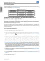
Summary of Revisions
The table below describes the revisions made to this manual.
Version Review Description
- R01 First edition
- R02 Cover update
- R03 General revision
- R04
Inclusion of new frame sizes models D and E
Update from IP54 to IP55 in frame sizes B and C
- R05 General revision
ATTENTION!
Parameters P0296 (Rated Line Voltage), P0400 (Rated Motor Voltage) and
P0403 (Rated Motor Frequency), were readjusted at the:
200...240 V / 220 / 230 V (S2, B2 and T2) models: P0296 = 0 (200 / 240 V),
P0400 = 220 V and P0403 = 60 Hz.
380...480 V (T4) models: P0296 = 3 (440 / 460 V), P0400 = 440 V and
P0403 = 60 Hz.
500...600 V (T5) models: P0296 = 6 (550 / 575 V), P0400 = 575 V and P0403
= 60 Hz.
For different values of line rated voltage and/or motor voltage and frequency,
set these parameters through the STARTUP menu, as presented in the user's
manual Section 5.2 START-UP on page 49.

Contents
English
1 SAFETY INSTRUCTIONS .................................................................1
1.1 SAFETY WARNINGS IN THE MANUAL .................................................1
1.2 SAFETY WARNINGS IN THE PRODUCT...............................................1
1.3 PRELIMINARY RECOMMENDATIONS ................................................. 2
2 GENERAL INSTRUCTIONS ..............................................................3
2.1 ABOUT THE MANUAL ...........................................................................3
2.2 ABOUT THE CFW700 ............................................................................. 3
2.3 IDENTIFICATION ....................................................................................6
2.4 LIST OF AVAILABLE MODELS .............................................................8
2.5 IDENTIFICATION LABELS .....................................................................8
2.6 RECEIVING AND STORAGE ..................................................................9
3 INSTALLATION AND CONNECTION ................................................10
3.1 MECHANICAL INSTALLATION .............................................................. 10
3.1.1 Installation Environment ..............................................................10
3.1.2 Mounting Considerations .............................................................10
3.2 ELECTRICAL INSTALLATION ................................................................ 11
3.2.1 Identification of the Power and Grounding Terminals ...............12
3.2.2 Power / Grounding Wiring and Fuses ......................................... 14
3.2.3 Power Connections ......................................................................15
3.2.3.1 Input Connections ............................................................16
3.2.3.2 Power Supply Capacity ...................................................16
3.2.3.3 Dynamic Braking (standard built-in for frame sizes
A, B, C and D and optional built-in for frame size E -
CFW700...DB...) .............................................................................16
3.2.3.4 Output Connections .........................................................18
3.2.4 Grounding Connections ...............................................................19
3.2.5 Control Connections ....................................................................20
3.2.6 Cable Distances ............................................................................24
3.3 INSTALLATION ACCORDING TO THE EUROPEAN DIRECTIVE OF
ELECTROMAGNETIC COMPATIBILITY ...................................................... 24
3.3.1 Conformal Installation .................................................................. 24
3.3.2 Emission and Immunity Levels .................................................... 25
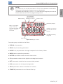
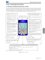
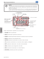
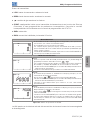
4 KEYPAD (HMI) AND BASIC PROGRAMMING ...............................26
4.1 INTEGRAL KEYPAD - HMI-CFW700 .....................................................26
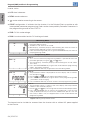
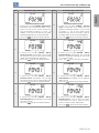
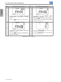
4.2 APPLICATIONS .......................................................................................29
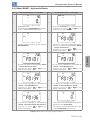
4.2.1 PID Regulator Application ............................................................29
4.2.1.1 Academic PID ................................................................... 33
4.2.2 Electronic Potentiometer Application (E.P.) ...............................39
4.2.3 Multispeed Application ................................................................41
4.2.4 3-Wire Start/Stop Command Application ................................... 44
4.2.5 Forward/Reverse Run Application ..............................................46

Contents
English
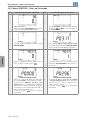
5 FIRST TIME POWER-UP AND START-UP .......................................49
5.1 PREPARE FOR START-UP ..................................................................... 49
5.2 START-UP ................................................................................................ 49
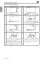
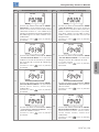
5.2.1 Oriented Start-up Menu ...............................................................50
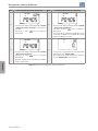
5.2.2 Basic Application Menu ..............................................................53
6 TROUBLESHOOTING AND MAINTENANCE ..................................54
6.1 FAULTS AND ALARMS ........................................................................... 54
6.2 SOLUTIONS FOR THE MOST FREQUENT PROBLEMS ......................54
6.3 INFORMATION FOR CONTACTING TECHNICAL SUPPORT .............. 55
6.4 PREVENTIVE MAINTENANCE ...............................................................56
6.5 CLEANING INSTRUCTIONS .................................................................57
7 OPTION KITS AND ACCESSORIES ................................................. 59
7.1 OPTION KITS .......................................................................................... 59
7.1.1 Built-in RFI Filter (only for frame sizes A, B, C and D) -
CFW700...C3... ........................................................................................ 59
7.1.2 Dynamic Braking IGBT (only for frame size E in 220 / 230 V
and 380…480 V models and for frame sizes D and E in 500…600 V
models) - CFW700...DB... .....................................................................59
7.1.3 Nema1 Protection Degree (only for frame sizes A, B, C and E) -
CFW700...N1... ........................................................................................ 59
7.1.4 IP55 Protection Degree (only for frame sizes B and C) -
CFW700...55... .........................................................................................59
7.1.5 IP21 Protection Degree (only for frame sizes A, B and C) -
CFW700...21... .........................................................................................59
7.1.6 STO Function - CFW700...Y1........................................................59
7.1.7 24 Vdc External Control Power Supply - CFW700...W1... ..........60
7.2 ACCESSORIES .......................................................................................60
8 TECHNICAL SPECIFICATIONS ........................................................62
8.1 POWER DATA ......................................................................................... 62
8.2 ELECTRICAL/GENERAL SPECIFICATIONS ......................................... 63
8.3 CODES AND STANDARDS ....................................................................65
8.4 CERTIFICATIONS ................................................................................... 65

CFW700 | 1
Safety Instructions
English
1 SAFETY INSTRUCTIONS
This manual provides information for the proper installation and operation of the CFW700
frequency inverter.
Only trained personnel, with proper qualifications, and familiar with this kind of equipment
and associated machinery shall plan and implement the installation, starting, operation, and
maintenance of this equipment. The personnel shall follow all the safety instructions described in
this manual and/or defined by the local regulations. Failure to comply with the safety instructions
may result in death, serious injury, and equipment damage.
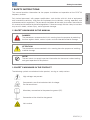
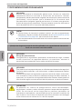
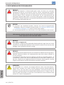
1.1 SAFETY WARNINGS IN THE MANUAL
DANGER!
The procedures recommended in this warning have the purpose of protecting
the user against death, serious injuries and considerable material damage.
ATTENTION!
The procedures recommended in this warning have the purpose of avoiding
material damage.
NOTE!
The text intents to supply important information for the correct understanding
and good operation of the product.
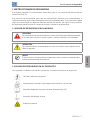
1.2 SAFETY WARNINGS IN THE PRODUCT
The following symbols are attached to the product, serving as safety notices:
High voltages are present.
Components sensitive to electrostatic discharge.
Do not touch them.
Mandatory connection to the protective ground (PE).
Connection of the shield to the ground.
Hot surface.

2 | CFW700
Safety Instructions
English
1.3 PRELIMINARY RECOMMENDATIONS
DANGER!
Always disconnect the main power supply before touching any electrical
device associated with the inverter. Several components may remain charged
with high voltage and/or in movement (fans), even after the AC power supply
has been disconnected or turned off. Wait at least 10 minutes to guarantee
the fully discharge of capacitors. Always connect the equipment frame to the
ground protection (PE).
NOTE!
Frequency inverters may cause interference in other electronic devices. Follow
the recommendations listed in Chapter 3 INSTALLATION AND CONNECTION
on page 10, to minimize these effects.
Fully read this manual before installing or operating the inverter.
Do not perform a withstand voltage test on any part of the inverter!
If needed, please, consult WEG.
DANGER!
Crushing Hazard
In order to ensure safety in load lifting applications, electric and/or mechanical
devices must be installed outside the inverter for protection against accidental
fall of load.
DANGER!
This product was not designed to be used as a safety element. Additional
measures must be taken so as to avoid material and personal damages.
The product was manufactured under strict quality control, however, if installed
in systems where its failure causes risks of material or personal damages,
additional external safety devices must ensure a safety condition in case of a
product failure, preventing accidents.
ATTENTION!
When in operation, electric energy systems - such as transformers, converters,
motors and cables - generate electromagnetic fields (EMF), posing a risk to
people with pacemakers or implants who stay in close proximity to them.
Therefore, those people must stay at least 2 meters away from such equipment.

CFW700 | 3
General Instructions
English
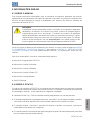
2 GENERAL INSTRUCTIONS
2.1 ABOUT THE MANUAL
The purpose of this manual is to provide the basic information needed to install, start-up in
the V/f control mode (scalar), and troubleshoot the most common problems of the CFW700
frequency inverter series.
ATTENTION!
The operation of this equipment requires installation instructions and detailed
operation provided in the user's manual, programming manual and manuals/
guides for kits and accessories. The user's manual and the parameters quick
reference are supplied in a hard copy together with the inverter. The user guides
are also provided in a hard copy along with the kit/accessories. The other
manuals are available at www.weg.net. A printed copy of the files available on
WEG’s website can be requested at your local WEG dealer.
Some of the figures and tables are available in the appendixes. The APPENDIX A - DIAGRAMS
AND FIGURES on page 207 shows the figures and the APPENDIX B - TECHNICAL
SPECIFICATIONS on page 218 shows the technical specifications. The information is available
in three languages.
Please refer to the following technical manuals for further information:
CFW700 Programming Manual.
DeviceNet Communication Manual.
CANopen Communication Manual.
Profibus DP Communication Manual.
Modbus Communication Manual.
SoftPLC Manual.
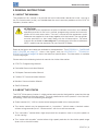
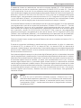
2.2 ABOUT THE CFW700
The CFW700 frequency inverter is a high performance product designed for speed and torque
control of threephase induction motors. The main characteristic of this product is the “Vectrue”
technology, which has the following advantages:
Scalar control (V/f), VVW or vector control programmable in the same product.
The vector control may be programmed as “sensorless” (which means standard motors
without using encoders) or as “vector control” with the use of an encoder.
The “sensorless” control allows high torque and fast response, even in very low speeds or
at the starting.
The “vector with encoder” control allows high speed precision for the whole speed range
(even with a standstill motor).

4 | CFW700
General Instructions
English
“Optimal Braking” function for the vector control, allowing the controlled braking of the motor
and avoiding external braking resistor for some applications.
“Self-Tuning” feature for vector control. It allows the automatic adjustment of the regulators
and control parameters from the identification (also automatic) of the motor parameters and
load.
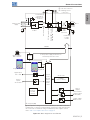
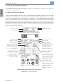
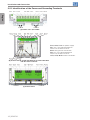
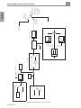
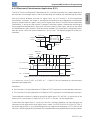
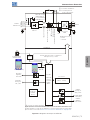
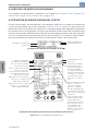
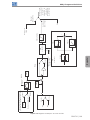
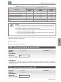
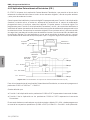
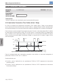
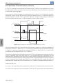
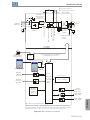
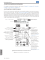
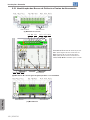
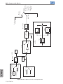
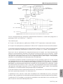
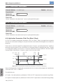
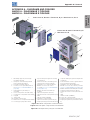
The main components of the CFW700 can be viewed in Figure A.1 on page 207.

CFW700 | 5
General Instructions
English
Analog
inputs
AI1 and AI2
FLASH
memory
module
(Slot 5)
Digital inputs
DI1 to DI8
Control power supply and interfaces
between power and control
RS-485
PC
POWER
CONTROL
Three-phase
rectifier
C3 RFI filter (*)
(available in
CFW700...C3...
inverters)
Motor
U/T1
V/T2
W/T3
DC+ DC-BR
Inverter
with
IGBT
transistors
Mains power
supply
R/L1/L
S/L2/N
T/L3
= DC link connection
= Braking resistor
connection
Pre-
charge
WPS software
WLP software
DC link chokes
DC link capacitor bank
Braking IGBT (available in
CFW700...DB... inverters)
RFI filter
Keypad
CC700
Control
board
with a
32 bits
"RISC"
CPU
Analog
outputs
AO1 and AO2
Digital output
DO1 (RL1)
Digital outputs
DO2 to DO5
Keypad (remote)
Feedback:
- voltage
- current
PE
PE
COMM 1
(Slot 3 - Green)
Accessories
= Keypad (HMI)
(*) The capacitor to the ground of the C3 RFI filter (it is possible to meet the
requirements of category C2 with this filter on mechanics A models) must be
disconnected for IT networks and grounded delta power supplies. Please
refer to Item 3.2.3.1 Input Connections on page 16.
Figure 2.1: Block diagram for the CFW700

6 | CFW700
General Instructions
English
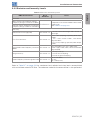
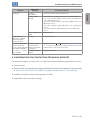
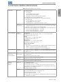
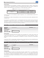
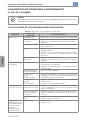
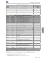
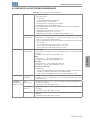
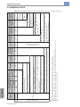
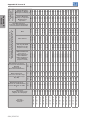
2.3 IDENTIFICATION
Table 2.1: Identification of the CFW700 inverters
Product
and
Series
Model Identification
Braking
(1)
Enclosure
(1)
Conducted
Emission
Level
(1)
Discon.
Switch
(5)
Safety
Stop
(3)
External
Control
Voltage
Special
Hardware
Version
Special
Software
Version
Frame
Size
Rated
Output
Current
Number
of Power
Phases
Rated
Voltage
Eg.: CFW700 A 03P6 T 4 DB 20 C3 DS Y1 W1 --- --
Available options
CFW700
Refer to Table 2.2 on page 7.
Blank = not available
DS = with discon. switch
Blank =
standard.
NB = without dynamic braking (valid only for frame size
E inverters).
Sx =
special
software.
DB = with dynamic braking. Blank = standard.
20 = IP20.
(2)
Hxx or Kxx = special
hardware.
21 = IP21 (not available for frame size E inverters). Blank = not available.
N1 = Nema1 enclosure (UL Type 1) (protection degree according to
IEC: IP21 for frame sizes A, B and C and IP20 for frame sizes D and E).
W1 = 24 Vdc power supply,
independent of the control
voltage.
55 = IP55 (only for 200...240 V and 380...480 V models of frame sizes
B, C, D and E).
Blank = not available.
Blank = it is not in accordance with the standard conducted emission levels. Y1 = with STO function (Safe Torque Off)
according to EN 954-1/ISO 13849-1,
category 3.
C3 = according to category 3 (C3) of IEC 61800-3, with built-in C3 RFI filter.
(4)
Notes:
(1) The options available for each model are shown in Table 2.2 on page 7.
(2) This option is not available for frame size D inverters (the standard product is Nema1).
(3) This option is not available for frame size A inverters with the N1 option (Nema1 enclosure) or IP21.
(4) It is possible to meet the requirements of category C2 with this filter on mechanics A models. For further details, see Table B.7 on page 234.
(5) Only applicable to models with degree of protection IP55.

CFW700 | 7
General Instructions
English
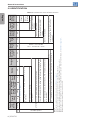
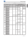
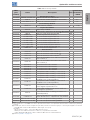
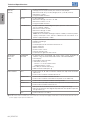
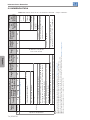
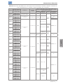
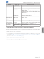
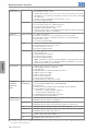
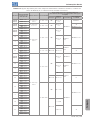
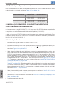
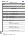
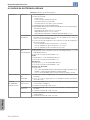
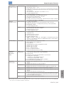
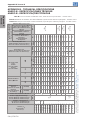
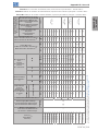
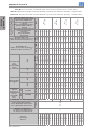
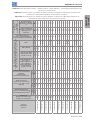
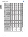
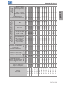
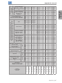
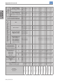
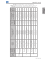
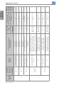
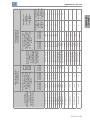
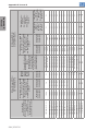
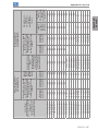
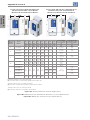
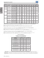
Table 2.2: Options available for each model according to the size, power supply, rated current and voltage
of the inverter
Frame
Size
Rated Output
Current for ND
Overload
Number of
Power Phases
Rated Voltage
Available Options for the Remaining Identification
Codes of the Inverters
(standard product is shown in bold)
Braking
Enclosure
(Protection
Degree)
Discon.
Switch
Conducted
Emission Level
A (IP20)
B (IP55)
06P0 = 6.0 A
B = single-phase or
three-phase
2 = 200…240 V DB
20, 21, N1
or 55
Blank
Blank
07P0 = 7.0 A
A (IP20)
B (IP55)
06P0 = 6.0 A
S = Single-phase 2 = 200…240 V DB
20, 21, N1
or 55
C3
07P0 = 7.0 A
10P0 = 10 A Blank or C3
A (IP20)
B (IP55)
07P0 = 7.0 A
T = three-phase
2 = 200…240 V DB
20, 21, N1
or 55
Blank or C3
10P0 = 10 A
13P0 = 13 A
16P0 = 16 A
B
24P0 = 24 A
20, 21, N1
or 55
Blank or DS
28P0 = 28 A
33P5 = 33.5 A
C
45P0 = 45 A
54P0 = 54 A
70P0 = 70 A
D
86P0 = 86 A
21, N1 or 55
Blank or DS
0105 = 105 A
E
0142 = 142 A
2 = 220…230 V NB or DB 20, N1 or 55 C30180 = 180 A
0211 = 211 A
A (IP20)
B (IP55)
03P6 = 3.6 A
T = three-phase 4 = 380 / 480 V
DB
20, 21, N1
or 55
Blank
Blank or C3
05P0 = 5.0 A
07P0 = 7.0 A
10P0 = 10 A
13P5 = 13.5 A
B
17P0 = 17 A
20, 21, N1
or 55
Blank or DS
24P0 = 24 A
31P0 = 31 A
C
38P0 = 38 A
45P0 = 45 A
58P5 = 58.5 A
D
70P5 = 70.5 A
21, N1 or 55
Blank or DS
88P0 = 88 A
E
0105 = 105 A
NB or DB 20, N1 or 55 C3
0142 = 142 A
0180 = 180 A
0211 = 211 A
B
02P9 = 2.9 A
T = three-phase 5 = 500...600 V
DB 20, 21 or N1
Blank
Blank or C3
04P2 = 4.2 A
07P0 = 7.0 A
10P0 = 10 A
12P0 = 12 A
17P0 = 17 A
C
22P0 = 22 A
27P0 = 27 A
32P0 = 32 A
44P0 = 44 A
D
22P0 = 22 A
NB or DB
21 or N1
27P0 = 27 A
32P0 = 32 A
44P0 = 44 A
E
53P0 = 53 A
20 or N1 C3
63P0 = 63 A
80P0 = 80 A
0107 = 107 A
0125 = 125 A
0150 = 150 A

8 | CFW700
General Instructions
English
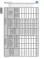
2.4 LIST OF AVAILABLE MODELS
The available inverter models are listed in Table B.1 on page 218, Table B.2 on page 219
and Table B.3 on page 220.
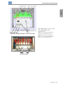
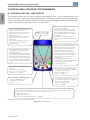
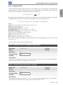
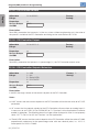
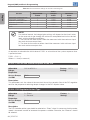
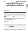
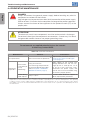
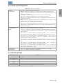
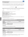
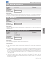
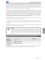
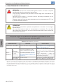
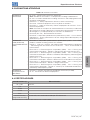
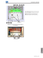
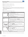
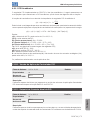
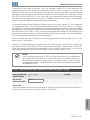
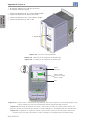
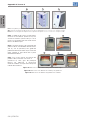
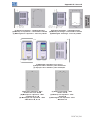
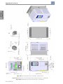
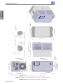
2.5 IDENTIFICATION LABELS
There are two nameplates on the CFW700: one complete nameplate is affixed to the side of the
inverter and a simplified one is located under the keypad. Please refer to Figure A.2 on page
208 to verify the position of these labels on the product. The nameplate under the keypad
allows the identification of the most important characteristics of the inverter even if they are
mounted side-by-side. When there is more than one inverter it is necessary to be careful not to
exchange the inverter covers (front cover in case of inverters frame sizes A, B or C and control
rack cover for inverters frame sizes D and E) because there are individual information labels
under the keypad of each inverter.
CFW700 model
Manufacturing dateWEG part number
Serial number
(a) Nameplate located under the keypad
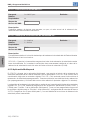
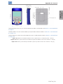
CFW700 model
WEG part number
Manufacturing date
Inverter net weight
Input rated data (voltage,
number of phases, rated
currents for operation with
ND and HD overload cycles,
and frequency)
Output rated data
(voltage, number of
phases, rated currents for
operation with ND and HD
overload cycles, overload
currents for 1 min and 3 s,
and frequency range)
The maximum output
frequency depends on the
settings of the motor rated
frequency, control mode
and inverter switching
frequency. For further
details, see Table 8.1 on
page 63.
Maximum ambient
temperature (without
derating) for ND overload
with open spaces for
ventilation around the
inverter (refer to the
dimensions A, B, C and D
in Figure B.3 on page 242)
Serial number
Current specifications
for operation with normal
overload cycle (ND)
Current specifications
for operation with heavy
overload cycle (HD)
(b) Nameplate affixed to the side of the inverter
Figure 2.2: (a) and (b) Nameplates

CFW700 | 9
General Instructions
English
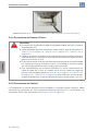
2.6 RECEIVING AND STORAGE
The CFW700 comes packaged in a cardboard box up to frame size C inverter models. The
bigger models are packed in wooden box. There is an identification label affixed to the outside
of this package, the same one that is affixed to the side of the CFW700 inverter.
Follow the steps below to open the packaging of models larger than frame size C:
1. Put the shipping container over a flat and stable area with the assistance of another two
people.
2. Open the wood crate.
3. Remove all the packing material (the cardboard or styrofoam protection) before removing
the inverter.
Check the following items once the inverter is delivered:
Verify that the CFW700 nameplate corresponds to the model number on your purchase order.
Inspect the CFW700 for external damage during transportation.
Report any damage immediately to the carrier that delivered your CFW700 inverter.
If CFW700 is to be stored for some time before use, be sure that it is stored in a clean and dry
location that conforms to the storage temperature specification (between -25 °C and 60 °C
(-13 °F and 140 °F)). Cover the inverter to prevent dust accumulation inside it.
ATTENTION!
Capacitor reforming is required if drives are stored for long periods of time
without power. Refer to Section 6.4 PREVENTIVE MAINTENANCE on page
56.

10 | CFW700
Installation and Connection
English
3 INSTALLATION AND CONNECTION
3.1 MECHANICAL INSTALLATION
3.1.1 Installation Environment
Avoid installing the inverter in an area with:
Direct exposure to sunlight, rain, high humidity, or sea-air.
Inflammable or corrosive gases or liquids.
Excessive vibration.
Dust, metallic particles, and oil mist.
Environment conditions for the operation of the inverter:
Inverter surrounding temperature: from -10 ºC up to Ta according to the Table B.5 on page 223.
A current derating of 2 % is necessary for each degree Celsius above Ta up to a limit of:
- 60 °C for models of frames A, B, C and D with IP2X or Nema1 degree of protection.
- 55 °C for models of frame E with IP2X or Nema1 degree of protection.
- 50 °C for all models with IP55 degree of protection.
Humidity: from 5 % to 95 % non-condensing.
Altitude: up to 1000 m (3,300 ft) - standard conditions (no derating required).
From 1000 m to 4000 m (3,300 ft to 13,200 ft) - current derating of 1 % each 100 m (or 0.3 %
each 100 ft) above 1000 m (3,300 ft) altitude.
From 2000 m to 4000 m (6,600 ft to 13,200 ft) above sea level - maximum voltage reduction
(240 V for 200...240 V models, 230 V for 220...230 V models, 480 V for 380...480 V models
and 600 V for 500...600 V models) of 1.1 % for each 100 m (330 ft) above 2000 m (6,600 ft).
Pollution degree: 2 (according to EN50178 and UL508C) with non-conductive pollution.
Condensation shall not originate conduction through the accumulated residues.
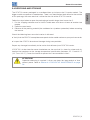
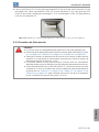
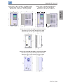
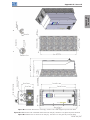
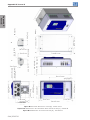
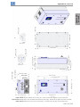
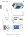
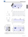
3.1.2 Mounting Considerations
External dimensions, fixing holes position and net weight of the inverter are presented at Figure
B.2 on page 240 and Figure B.3 on page 242. Please refer to Figure B.4 on page 243 to
Figure B.11 on page 250 for more details of each inverter size.
Install the inverter upright on a flat surface. First place the screws on the surface where the
drive is going to be installed, install the drive and then tighten the screws.
Frame size E inverters with N1 option (CFW700E...N1...):
After fixing the inverter, install the upper Nema 1 kit on the inverter using the two M8 screws
provided with the product.

CFW700 | 11
Installation and Connection
English
Let the minimum clearances specified in Figure B.3 on page 242 in order to allow air circulation
for cooling. It is possible to assembly frame sizes A, B and C inverters with IP20 protection
degree (CFW700… 20…) side by side without lateral spacing, i.e., with the D distance presented
in Figure B.3 on page 242 equal to zero.
Do not install heat sensitive components right above the inverter.
ATTENTION!
When arranging two or more inverters vertically, respect the minimum
clearance A + B (Figure B.3 on page 242) and provide an air deflecting
plate so that the heat rising up from the bottom inverter does not affect the
top inverter.
Provide conduit for physical separation of the signal, control, and power
conductors (refer to Section 3.2 ELECTRICAL INSTALLATION on page 11).
Please refer to Figure B.3 on page 242 for surface and flange mounting data. The inverter
dissipated power at rated condition for surface and flange mounting is presented in Table B.5
on page 223. Remove the drive mounting brackets for flange mounting. The protection degree
of the inverter outside the panel is IP55 for flange mounting. It is necessary to provide proper
seal for the opening where the inverter is installed to ensure the protection degree of the panel.
Example: sealing with silicone.
Please refer to Figure A.4 on page 210 for more details on the access to the control and
power terminals.
3.2 ELECTRICAL INSTALLATION
DANGER!
The following information is merely a guide for proper installation. Comply
with applicable local regulations for electrical installations.
Make sure the AC power supply is disconnected before starting the
installation.

12 | CFW700
Installation and Connection
English
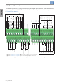
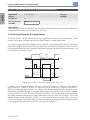
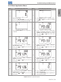
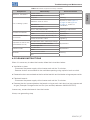
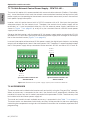
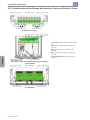
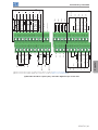
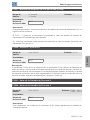
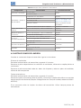
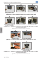
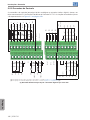
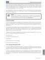
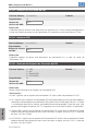
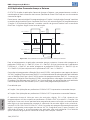
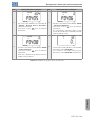
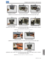
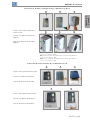
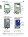
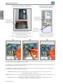
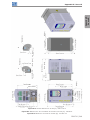
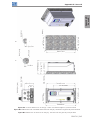
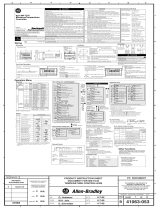
3.2.1 Identification of the Power and Grounding Terminals
Ground
Ground
R/L1
R/L1
R/L1
S/L2
S/L2
S/L2
T/L3
T/L3
T/L3
DC-
DC-
DC+
DC+
U/T1
U/T1
V/T2
V/T2
W/T3
W/T3
BR
BR
(a) Frame sizes A, B and C
(b) Frame sizes B and C with degree of protection IP55
and disconnect switch
Ground Ground
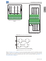
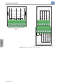
(c) Frame size D
R/L1 S/L2 T/L3 DC- DC+ U/T1 V/T2 W/T3
BR
Ground
R/L1, S/L2, T/L3: AC power supply.
DC-: this is the negative potential
terminal in the DC link circuit.
BR: braking resistor connection.
DC+: this is the positive potential
terminal in the DC link circuit.
U/T1, V/T2, W/T3: motor connection.

CFW700 | 13
Installation and Connection
English
R/L1 S/L2 T/L3
DC- DC+ U/T1 V/T2 W/T3BR
Ground
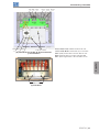
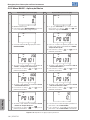
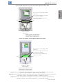
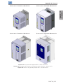
(d) Frame size D with degree of protection IP55
R/L1, S/L2, T/L3: AC power supply.
U/T1, V/T2, W/T3: motor
connwwection.
DC+: this is the positive potential
terminal in the DC link circuit.
BR: braking resistor connection.
DC-: this is the negative potential
terminal in the DC link circuit.
Ground
(4xM8, 4xM5)
(e) Frame size E

14 | CFW700
Installation and Connection
English
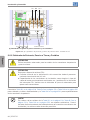
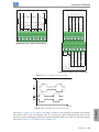
R/L1 S/L2 T/L3
DC- DC+
U/T1
V/T2
W/T3
BR
Ground
(f) Frame size E with degree of protection IP55
Figura 3.1: (a) to (f) Power terminals and grounding points - frame sizes A to E
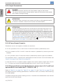
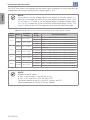
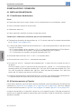
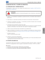
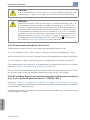
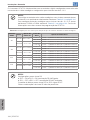
3.2.2 Power / Grounding Wiring and Fuses
ATTENTION!
Use proper cable lugs for the power and grounding connection cables.
ATTENTION!
Residual Current Device (RCD):
When installing an RCD to guard against electrical shock, only devices with
a trip current of 300 mA should be used on the supply side of the inverter.
Depending on the installation (motor cable length, cable type, multimotor
configuration, etc.), the RCD protection may be activated. Contact the RCD
manufacturer for selecting the most appropriate device to be used with
inverters.
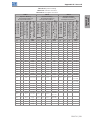
Refer to Table B.1 on page 218, Table B.2 on page 219 and Table B.3 on page 220 for the
recommended wiring and fuses and Table B.6 on page 231 for the specifications of the power
terminals.
NOTE!
The gauges values presented in Table B.1 on page 218, Table B.2 on page 219
and Table B.3 on page 220 are for reference only. Installation conditions and the
maximum permitted voltage drop shall be considered for the proper wiring sizing.

CFW700 | 15
Installation and Connection
English
Input fuses
The fuses to be used at the input must be HS (High-Speed) type with I
2
t equal or lower the
value indicated in the Table B.1 on page 218, Table B.2 on page 219 and Table B.3 on
page 220 (consider extinction current value in cold situation (it is not the fusion value)), to
protect the inverter diode rectifiers and input wiring.
In order to meet UL requirements, use class J fuses at the inverter supply with a current not
higher than the values presented in Table B.1 on page 218, Table B.2 on page 219 and
Table B.3 on page 220.
Optionally, slow blow fuses can be used at the input. They shall be sized for 1.2 x the rated
input current of the inverter. In this case, the installation is protected against short-circuit, but
not the inverter input rectifier. This may result in major damage to the inverter in the event of
an internal component failure.
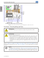
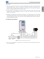
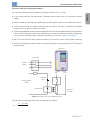
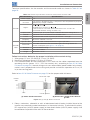
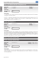
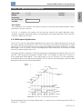
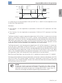
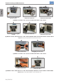
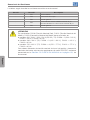
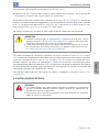
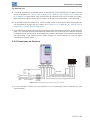
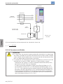
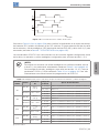
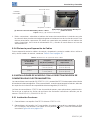
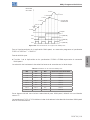
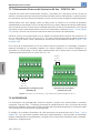
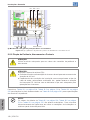
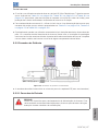
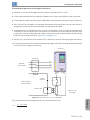
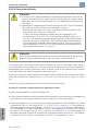
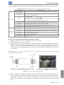
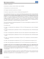
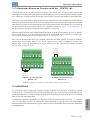
3.2.3 Power Connections
Shielding
PE
Disconnect
switch
Fuses
R
S
T
Power
supply
PE W V U
PE R S T U V W PE
Figure 3.2: Power and grounding connections
The switch-disconnector is not necessary if the inverter has the DS optional item (with
switch-disconnector).
A página está carregando...
A página está carregando...
A página está carregando...
A página está carregando...
A página está carregando...
A página está carregando...
A página está carregando...
A página está carregando...
A página está carregando...
A página está carregando...
A página está carregando...
A página está carregando...
A página está carregando...
A página está carregando...
A página está carregando...
A página está carregando...
A página está carregando...
A página está carregando...
A página está carregando...
A página está carregando...
A página está carregando...
A página está carregando...
A página está carregando...
A página está carregando...
A página está carregando...
A página está carregando...
A página está carregando...
A página está carregando...
A página está carregando...
A página está carregando...
A página está carregando...
A página está carregando...
A página está carregando...
A página está carregando...
A página está carregando...
A página está carregando...
A página está carregando...
A página está carregando...
A página está carregando...
A página está carregando...
A página está carregando...
A página está carregando...
A página está carregando...
A página está carregando...
A página está carregando...
A página está carregando...
A página está carregando...
A página está carregando...
A página está carregando...
A página está carregando...
A página está carregando...
A página está carregando...
A página está carregando...
A página está carregando...
A página está carregando...
A página está carregando...
A página está carregando...
A página está carregando...
A página está carregando...
A página está carregando...
A página está carregando...
A página está carregando...
A página está carregando...
A página está carregando...
A página está carregando...
A página está carregando...
A página está carregando...
A página está carregando...
A página está carregando...
A página está carregando...
A página está carregando...
A página está carregando...
A página está carregando...
A página está carregando...
A página está carregando...
A página está carregando...
A página está carregando...
A página está carregando...
A página está carregando...
A página está carregando...
A página está carregando...
A página está carregando...
A página está carregando...
A página está carregando...
A página está carregando...
A página está carregando...
A página está carregando...
A página está carregando...
A página está carregando...
A página está carregando...
A página está carregando...
A página está carregando...
A página está carregando...
A página está carregando...
A página está carregando...
A página está carregando...
A página está carregando...
A página está carregando...
A página está carregando...
A página está carregando...
A página está carregando...
A página está carregando...
A página está carregando...
A página está carregando...
A página está carregando...
A página está carregando...
A página está carregando...
A página está carregando...
A página está carregando...
A página está carregando...
A página está carregando...
A página está carregando...
A página está carregando...
A página está carregando...
A página está carregando...
A página está carregando...
A página está carregando...
A página está carregando...
A página está carregando...
A página está carregando...
A página está carregando...
A página está carregando...
A página está carregando...
A página está carregando...
A página está carregando...
A página está carregando...
A página está carregando...
A página está carregando...
A página está carregando...
A página está carregando...
A página está carregando...
A página está carregando...
A página está carregando...
A página está carregando...
A página está carregando...
A página está carregando...
A página está carregando...
A página está carregando...
A página está carregando...
A página está carregando...
A página está carregando...
A página está carregando...
A página está carregando...
A página está carregando...
A página está carregando...
A página está carregando...
A página está carregando...
A página está carregando...
A página está carregando...
A página está carregando...
A página está carregando...
A página está carregando...
A página está carregando...
A página está carregando...
A página está carregando...
A página está carregando...
A página está carregando...
A página está carregando...
A página está carregando...
A página está carregando...
A página está carregando...
A página está carregando...
A página está carregando...
A página está carregando...
A página está carregando...
A página está carregando...
A página está carregando...
A página está carregando...
A página está carregando...
A página está carregando...
A página está carregando...
A página está carregando...
A página está carregando...
A página está carregando...
A página está carregando...
A página está carregando...
A página está carregando...
A página está carregando...
A página está carregando...
A página está carregando...
A página está carregando...
A página está carregando...
A página está carregando...
A página está carregando...
A página está carregando...
A página está carregando...
A página está carregando...
A página está carregando...
A página está carregando...
A página está carregando...
A página está carregando...
A página está carregando...
A página está carregando...
A página está carregando...
A página está carregando...
A página está carregando...
A página está carregando...
A página está carregando...
A página está carregando...
A página está carregando...
A página está carregando...
A página está carregando...
A página está carregando...
A página está carregando...
A página está carregando...
A página está carregando...
A página está carregando...
A página está carregando...
A página está carregando...
A página está carregando...
A página está carregando...
A página está carregando...
A página está carregando...
A página está carregando...
A página está carregando...
A página está carregando...
A página está carregando...
A página está carregando...
A página está carregando...
A página está carregando...
A página está carregando...
A página está carregando...
A página está carregando...
A página está carregando...
A página está carregando...
A página está carregando...
A página está carregando...
A página está carregando...
A página está carregando...
A página está carregando...
A página está carregando...
A página está carregando...
A página está carregando...
A página está carregando...
A página está carregando...
A página está carregando...
-
 1
1
-
 2
2
-
 3
3
-
 4
4
-
 5
5
-
 6
6
-
 7
7
-
 8
8
-
 9
9
-
 10
10
-
 11
11
-
 12
12
-
 13
13
-
 14
14
-
 15
15
-
 16
16
-
 17
17
-
 18
18
-
 19
19
-
 20
20
-
 21
21
-
 22
22
-
 23
23
-
 24
24
-
 25
25
-
 26
26
-
 27
27
-
 28
28
-
 29
29
-
 30
30
-
 31
31
-
 32
32
-
 33
33
-
 34
34
-
 35
35
-
 36
36
-
 37
37
-
 38
38
-
 39
39
-
 40
40
-
 41
41
-
 42
42
-
 43
43
-
 44
44
-
 45
45
-
 46
46
-
 47
47
-
 48
48
-
 49
49
-
 50
50
-
 51
51
-
 52
52
-
 53
53
-
 54
54
-
 55
55
-
 56
56
-
 57
57
-
 58
58
-
 59
59
-
 60
60
-
 61
61
-
 62
62
-
 63
63
-
 64
64
-
 65
65
-
 66
66
-
 67
67
-
 68
68
-
 69
69
-
 70
70
-
 71
71
-
 72
72
-
 73
73
-
 74
74
-
 75
75
-
 76
76
-
 77
77
-
 78
78
-
 79
79
-
 80
80
-
 81
81
-
 82
82
-
 83
83
-
 84
84
-
 85
85
-
 86
86
-
 87
87
-
 88
88
-
 89
89
-
 90
90
-
 91
91
-
 92
92
-
 93
93
-
 94
94
-
 95
95
-
 96
96
-
 97
97
-
 98
98
-
 99
99
-
 100
100
-
 101
101
-
 102
102
-
 103
103
-
 104
104
-
 105
105
-
 106
106
-
 107
107
-
 108
108
-
 109
109
-
 110
110
-
 111
111
-
 112
112
-
 113
113
-
 114
114
-
 115
115
-
 116
116
-
 117
117
-
 118
118
-
 119
119
-
 120
120
-
 121
121
-
 122
122
-
 123
123
-
 124
124
-
 125
125
-
 126
126
-
 127
127
-
 128
128
-
 129
129
-
 130
130
-
 131
131
-
 132
132
-
 133
133
-
 134
134
-
 135
135
-
 136
136
-
 137
137
-
 138
138
-
 139
139
-
 140
140
-
 141
141
-
 142
142
-
 143
143
-
 144
144
-
 145
145
-
 146
146
-
 147
147
-
 148
148
-
 149
149
-
 150
150
-
 151
151
-
 152
152
-
 153
153
-
 154
154
-
 155
155
-
 156
156
-
 157
157
-
 158
158
-
 159
159
-
 160
160
-
 161
161
-
 162
162
-
 163
163
-
 164
164
-
 165
165
-
 166
166
-
 167
167
-
 168
168
-
 169
169
-
 170
170
-
 171
171
-
 172
172
-
 173
173
-
 174
174
-
 175
175
-
 176
176
-
 177
177
-
 178
178
-
 179
179
-
 180
180
-
 181
181
-
 182
182
-
 183
183
-
 184
184
-
 185
185
-
 186
186
-
 187
187
-
 188
188
-
 189
189
-
 190
190
-
 191
191
-
 192
192
-
 193
193
-
 194
194
-
 195
195
-
 196
196
-
 197
197
-
 198
198
-
 199
199
-
 200
200
-
 201
201
-
 202
202
-
 203
203
-
 204
204
-
 205
205
-
 206
206
-
 207
207
-
 208
208
-
 209
209
-
 210
210
-
 211
211
-
 212
212
-
 213
213
-
 214
214
-
 215
215
-
 216
216
-
 217
217
-
 218
218
-
 219
219
-
 220
220
-
 221
221
-
 222
222
-
 223
223
-
 224
224
-
 225
225
-
 226
226
-
 227
227
-
 228
228
-
 229
229
-
 230
230
-
 231
231
-
 232
232
-
 233
233
-
 234
234
-
 235
235
-
 236
236
-
 237
237
-
 238
238
-
 239
239
-
 240
240
-
 241
241
-
 242
242
-
 243
243
-
 244
244
-
 245
245
-
 246
246
-
 247
247
-
 248
248
-
 249
249
-
 250
250
-
 251
251
-
 252
252
-
 253
253
-
 254
254
-
 255
255
-
 256
256


WEG CFW700 Manual do usuário
- Categoria
- Adaptadores de energia
- Tipo
- Manual do usuário
em outras línguas
- español: WEG CFW700 Manual de usuario
- English: WEG CFW700 User manual
Artigos relacionados
-
WEG CFW11 Guia de usuario
-
-
-
WEG CFW700 Guia rápido
-
-
-
-
WEG CFW701 Manual do usuário
-
-
Outros documentos
-
Omron VS MINI J7 Manual do proprietário
-
Bticino 26108N Instruções de operação
-
 Hach IO9000 User Instructions
-
SolarEdge SolarEdge Home Interface de backup para uso com o SolarEdge Home Hub Inversor – Monofásico Guia de instalação
-
Intelbras EGT 125000 HMAX Guia de instalação
-
ABB ACS580-04 Quick Installation Manual
-
Fagor SR-28 User Instructions
-
-
 Rockwell Automation Allen-Bradley 900-TC32 Manual do usuário
-
Greenlee Tone Ranger Quick Guide (Braz. Port.) Manual do usuário

